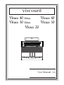
1
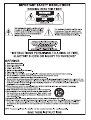
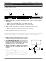
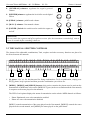
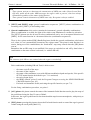
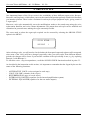
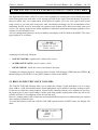
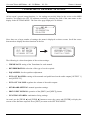
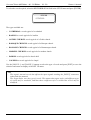
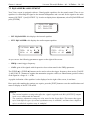
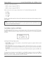
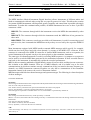
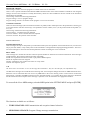
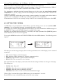
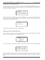
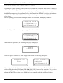
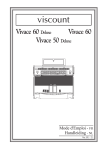
viscount
Vivace 40 Deluxe
Vivace 40
Vivace 30 Deluxe
Vivace 30
Vivace 20
PEDAL
FIELD
FIELD
EXIT
VALUE
+
VALUE
ENTER
GENERAL
REVERB
PEDAL
MAN.I
Prinzipal
Subbass
Violon
16'
16'
16'
THRU
Gedackt
8'
Choralbass
4'
MAN. I
Mixtur
Posaune
Trompete
Klarine
4 f.
16'
8'
4'
Coupler
I/P
Coupler
II / P
OUT
MIDI
IN
MAN. II
Prinzipal
Prinzipal
Rohrflöte
Oktave
Spitzflöte
Oktave
Kornett
Mixtur
Trompete
Trompete
16'
8'
8'
4'
4'
2'
3 f.
4 f.
16'
8'
Tremulant
Coupler
II / I
Prinzipal
Bourdon
Gamba
8'
8'
8'
Vox
Celeste
8'
Rohrflöte
Quintflöte
Waldflöte
Terz
Scharf
Oboe
Clarion
4'
2 2 / 3'
2'
13/5'
3 f.
8'
4'
Tremulant
viscount
POWER
S
HEADPHONES
Oktavbass
8'
L(MONO)
R
INPUT
MIDI
P
MIDI
I
MIDI
II
PREV
NEXT
HR
1
2
3
4
5
6
L(MONO)
R
OUTPUT
A.P
ENC
Vivace 40 Deluxe
T
C
L(+R)
R
OUTPUT - 1
MAN. I / PEDAL
L(+R)
R
OUTPUT - 2
MAN. II
User Manual - EN
Ver. EU - 2.1
Owner’s Manual
Viscount Vivace 40 Deluxe - 40 - 30 Deluxe - 30 - 20
INDEX
1. Important notes .................................................................................................................................. 39
1.1 Looking after the product .............................................................................................................. 39
1.2 Notes about the manual ................................................................................................................. 39
2. Controls and connection .................................................................................................................... 41
2.1 The front panel ............................................................................................................................... 41
2.2 The manual splitter controls .......................................................................................................... 42
2.3 Pedal board controls ...................................................................................................................... 44
2.4 The connections underneath the manuals ..................................................................................... 45
3. Main control unit ............................................................................................................................... 47
3.1 Switching on and main video page ............................................................................................... 47
3.2 An introduction to the instrument’s setup functions ..................................................................... 48
4. Organ Style ......................................................................................................................................... 50
5. Replacing voices and regulating voices volumes ............................................................................ 51
5.1 Regulating the voices volumes...................................................................................................... 51
5.2 Replacing voices ............................................................................................................................ 52
5.3 Checking the stop labels ................................................................................................................ 54
6. Temperament ...................................................................................................................................... 55
7. Instrument general settings .............................................................................................................. 56
7.1 Setting the tremulants .................................................................................................................... 57
7.2 Selecting the type of reverb ........................................................................................................... 57
7.3 Equalizers adjustment .................................................................................................................... 59
7.4 Signal routing on the audio outputs .............................................................................................. 60
7.5 Regulating the audio output volumes............................................................................................ 60
7.6 General manual settings ................................................................................................................ 61
7.7 [PREV] and [NEXT] pistons settings ........................................................................................... 62
7.8 Combination saving settings ......................................................................................................... 62
8. MIDI .................................................................................................................................................... 63
8.1 Selecting the channels ................................................................................................................... 65
8.2 Program Change message transmission ........................................................................................ 65
8.3 Setting the filters ............................................................................................................................ 66
9. Utility functions .................................................................................................................................. 67
9.1 Factory Setting ............................................................................................................................... 67
10. Appendix ........................................................................................................................................... 69
10.1 Demonstration songs ................................................................................................................... 69
10.2 Voice Local Off ............................................................................................................................ 69
10.3 Upgrading the operating system.................................................................................................. 70
37
Viscount Vivace 40 Deluxe - 40 - 30 Deluxe - 30 - 20
38
Owner’s Manual
Owner’s Manual
Viscount Vivace 40 Deluxe - 40 - 30 Deluxe - 30 - 20
1. IMPORTANT NOTES
1.1 LOOKING AFTER THE PRODUCT
•
Do not apply excessive force to the organ’s structures or the controls (knobs, stops, push-buttons,
etc.).
•
When possible, do not place the instrument close to units which generate strong interference, such as
radios, TVs, computer videos, etc.
•
Do not place the organ close to heat sources, in damp or dusty places or in the vicinity of strong
magnetic fields.
•
Do not expose the instrument to direct sunlight.
•
Never insert foreign bodies inside the instrument or pour liquids of any kind into it.
•
For cleaning, use only a soft brush or compressed air; never use detergents, solvents or alcohol.
•
Always use good quality screened cables for connection to amplification or diffusion systems. When
disconnecting cables from sockets, always take hold of the connector and not the cable itself; when
winding cables, do not knot or twist them.
•
Before making the connections ensure that the other units (especially amplification and diffusion
systems) you are about to connect are switched off. This will prevent noisy or even dangerous signal
peaks.
•
Connect the net cable to an earthed socket.
•
Check that the voltage corresponds to the voltage shown on the serial number plate of the organ.
•
If the organ is to be out of use for lengthy periods, disconnect the plug from the power socket.
1.2 NOTES ABOUT THE MANUAL
• Take good care of this manual.
• This manual is an integral part of the instrument. The descriptions and illustrations in this publication
are not binding.
• While the instrument’s essential characteristics remain the same, the manufacturer reserves the right
to make any modifications to parts, details or accessories considered appropriate to improve the
product or for requirements of a constructional or commercial nature, at any time and without
undertaking to update this publication immediately.
• All rights reserved; the reproduction of any part of this manual, in any form, without the manufacturer’s
specific written permission is forbidden.
39
Viscount Vivace 40 Deluxe - 40 - 30 Deluxe - 30 - 20
Owner’s Manual
• All the trademarks referred to in this manual are the property of the respective manufacturers.
• Please read all the information carefully, sothat you obtain the best performance and will from your
instrument.
• The codes or numbers in square brackets ([]) indicate the names of the buttons, sliders, trimmers and
connectors on the instrument. For example, [ENTER] refers to the ENTER button.
• The illustrations and display pages are purely guideline and may differ from those actually shown on
the display.
40
Owner’s Manual
Viscount Vivace 40 Deluxe - 40 - 30 Deluxe - 30 - 20
2. CONTROLS AND CONNECTIONS
2.1 THE FRONT PANEL
The front panel above the two manuals contains the stops, arranged section by section, used to activate
the organ’s registers.
Prinzipal
Subbass
Violon
16'
16'
16'
Oktavbass
8'
Gedackt
8'
1
2
3
PEDAL
MAN. I
MAN. II
Choralbass
4'
Mixtur
Posaune
Trompete
Klarine
4 f.
16'
8'
4'
Coupler
I/P
Coupler
II / P
Prinzipal
Prinzipal
Rohrflöte
Oktave
Spitzflöte
Oktave
Kornett
Mixtur
Trompete
Trompete
16'
8'
8'
4'
4'
2'
3 f.
4 f.
16'
8'
Tremulant
Coupler
II / I
Prinzipal
Bourdon
Gamba
8'
8'
8'
Vox
Celeste
8'
Rohrflöte
Quintflöte
Waldflöte
Terz
Scharf
Oboe
Clarion
4'
22/3'
2'
13/5'
3 f.
8'
4'
Tremulant
1. [PEDAL] section: this section contains the pedal board register stops. The following couplers are
also provided:
o [I/P]: the stops of the first manual will also play on the pedal board.
o [II/P]: the stops of the second manual will also play on the pedal board.
2. [MAN. I] section: contains the stops and tremulant of the first manual and the coupler:
o [II/I]: the stops of the second manual will also play on the first manual.
3. [MAN. II] section: second manual stops and tremulant.
On the left of the front display panel are located the other organ controls such as volumes, reverb adjustment
and display adjustment (only when the adjustment and configuration functions are displayed).
4. Display: alphanumeric display with 20 characters on 4 lines
for display of all the screens relating to the organ’s functions.
5. [FIELD ] and [FIELD ] buttons: buttons used to move
the cursor around within the display screens. The [FIELD ]
button moves the cursor to the field above (the one currently
selected) while [FIELD ] selects the field below.
6. [VALUE +] and [VALUE -] buttons: buttons for adjusting
parameters. [VALUE +] increases the value, [VALUE -]
decreases it.
7. [EXIT] and [ENTER] buttons: buttons for accessing or
exiting menu screens. [ENTER] is used to enter the menu or
function shown on the display or confirm any prompts from
the system. [EXIT] is used to exit the screen on the display
and return to the previous one, or abort any prompts from the
system.
41
4
FIELD
+
VALUE
FIELD
VALUE
ENTER
5
7
6
EXIT
Viscount Vivace 40 Deluxe - 40 - 30 Deluxe - 30 - 20
Owner’s Manual
8. [GENERAL] trimmer: regulates the organ’s general
volume.
8
9
GENERAL
REVERB
PEDAL
MAN.I
POWER
10
11
12
9. [REVERB] trimmer: regulates the level of the reverb digital
effects.
10. [PEDAL] trimmer: pedal board volume.
11. [MAN. I] trimmer: first manual volume.
12. [POWER ] Switch: the switch used to switch the organ on
and off.
WARNING!
Do not switch the organ on and off in rapid succession. After the instrument is switched off, wait at
least 10 seconds before switching it back on.
2.2 THE MANUAL SPLITTER CONTROLS
The pistons of the adjustable combinations, Tutti, couplers and other accessory functions are placed in
the areas between the manuals.
S
1
MIDI
P
MIDI
I
2
MIDI
II
PREV
NEXT
3
HR
1
2
3
4
5
4
6
A.P
5
Vivace 40 Deluxe
ENC
6
T
C
7
8
1. [S] piston: “Set” (or fix) function used for fixing combinations. To fix a combination, simply press
the [S] piston, keep it pressed and then press the combination you wish to fix.
2. [MIDI I], [MIDI II] and [MIDI P] buttons: this section contains the pistons used to activate the
transmission of MIDI note codes on the [MIDI OUT] port (in the recess underneath the first manual)
in response to the notes played on the manuals.
The LED of each piston displays the status of transmission on the relative MIDI channel as follows:
o Piston illuminated: note code transmission enabled
o Piston off: note code transmission disabled
[MIDI I] controls transmission of the notes played on the first manual, [MIDI II] controls the notes
played on the second manual, and [MIDI P] the notes played on the pedal board.
42
Owner’s Manual
Viscount Vivace 40 Deluxe - 40 - 30 Deluxe - 30 - 20
N.B.
- These pistons activate or deactivate the transmission of MIDI note codes (Note On and Note
Off) only, unlike all the other MIDI messages the organ is able to process, which are always
transmitted regardless of the status of this function.
- These pistons control transmission of MIDI notes only. Reception is always enabled.
3. [NEXT] and [PREV.] stops: general combination sequencers. [NEXT] selects combinations in
ascending order, [PREV.] in descending order.
4. General combinations: this section contains the instrument’s general adjustable combinations.
When a combination is recalled, the light of the relative stop illuminates to confirm its activation.
The [NEXT] pistons can also be used to select combinations one by one in an upward direction and
[PREV.] for the same function in a downward direction (combination sequencers).
There is also a piston marked [HR] (Handle Registers) beside the general combinations; also known
as 0, when it is on it automatically memorises the register status. This piston’s main function is to
restore, during use of the combinations, the “hand-made” stop setup created when the [HR] button
was on.
Remember that an HR setup is not modified if the stops are switched on and off by hand when a
combination on the same section is selected (i.e. with the HR off).
N.B.
The contents of the HR are not retained when the organ is switched off.
Each combination (including HR and Tutti) is able to store:
-
the status (on/off) of the stops
the status of the couplers
the status of the tremulants (even with different modulation depths and speeds, if the specific
SET-UP menu function described in par. 7.9 is activated)
the style (Organ Style)
the MIDI controls (point 2) and the Program Changes set using the SEND PROGRAM
CHANGE function (par. 8.2)
Enclosed and Automatic Pedal (activating the specific function, see par. 7.9).
For the fixing combinations procedure, see point 1.
5. [A.P.] piston: this piston controls the status of the Automatic Pedal function used to play the stops of
the pedal board using the first 32 notes of Man.I.
In this case, the organ’s pedal board is deactivated and the stops become monophonic, with priority to
the lowest note.
6. [ENC] piston: pressing this piston activates the Enclosed function used to control the organ’s general
volume using the swell pedal [MAN. II].
43
Viscount Vivace 40 Deluxe - 40 - 30 Deluxe - 30 - 20
Owner’s Manual
N.B.
When the Enclosed function is activated, the volumes of the first manual and pedal board are
immediately set in relation to the position of the [MAN. II] swell pedal. When the Enclosed function
is deactivated, the volumes of the above sections are immediately reset in relation to the position of
the [MAN. I / PEDAL] swell pedal.
7. [T] piston: piston used for switching the Tutti on and off.
The voice composition of the Tutti function is programmable. To set a new configuration, switch on
the stops and couplers of your choice, press [S], keep it pressed and then press the [T] piston.
8. [C] piston: Cancel piston, which switches off all the stops, tremulants, couplers and pistons on any
manual divisions active, then resets the HR.
2.3 PEDAL BOARD CONTROLS
MAN. I / PEDAL
MAN. II
1
2
1. [MAN. I / PEDAL] pedal (not present on Vivace 20): swell pedal used to control the volume of the
first manual and pedal board.
2. [MAN. II] pedal: you can use this swell pedal to control the volume of the second manual.
N.B.
The trimmer volume controls on the left of the manuals allow balancing of the sections; once you
have set the levels best suited to your taste and the sound balance you require, they will not require
frequent adjustment.
The swell pedals, on the other hand, allow continuous control of the volumes, enabling you to
obtain all the dynamic effects you wish. Apart from regulating the volume, the swell pedals also
simulate the variation in timbre of the stops which would occur in the swell boxes of pipe organs.
44
Owner’s Manual
Viscount Vivace 40 Deluxe - 40 - 30 Deluxe - 30 - 20
2.4 THE CONNECTIONS UNDERNEATH THE MANUALS
In the left of the organ, under the surface which contains the manuals and side panels, there is a small
recess containing various connectors for connecting the organ to remote sound and MIDI devices.
1
HEADPHONES
2
THRU
OUT
MIDI
3
IN
L(MONO)
R
INPUT
4
L(MONO)
R
OUTPUT
1. [HEADPHONES] connector: Jack socket to which a headphone set can be connected. With
headphones connected, the organ’s internal amplification is cut off.
N.B.
To obtain the best results from the [HEADPHONES] output, phones with impedance of at least 16Ω
should be used.
2. [MIDI] connectors: five-pin DIN connectors for connection of instruments with MIDI interface.
The [IN] connector allows receipt of MIDI data generated by remote MIDI sources, the [OUT]
connector transmits the MIDI messages generated by the Vivace, and the [THRU] connector transmits
the MIDI data exactly as received at the [IN] connector.
3. [INPUT] connectors: RCA line inputs which allow other instruments to be played using the organ’s
internal amplification. If the source is monophonic use the L(MONO) connector only.
4. [OUTPUT] connectors: RCA line outputs for the unamplified signal, for connection of optional
amplified speakers, remote amplification systems or recording systems. To use a monophonic signal,
connect to the [L/(MONO)] connector only.
45
Viscount Vivace 40 Deluxe - 40 - 30 Deluxe - 30 - 20
Owner’s Manual
Under the keyboards on the right side you will find the stereo line in and line out sockets.
In the bottom of the rear panel there are two more pairs of line audio outputs.
The main difference between these outputs and the ones on the left is that the latter contain the signal
generated by the organ, while on the right connectors, the signals of the individual manuals and pedal
board are routed to and adjusted on the individual outputs in accordance with the relative settings on the
display (for more information see points 7.5 and 7.6).
L(+R)
R
OUTPUT - 1
L(+R)
R
OUTPUT - 2
1
1. [OUTPUT 1] and [OUTPUT 2] connectors: Jack line outputs carrying the organ signal in accordance
with the routing set by means of the function on display. With the Factory Settings active, the signals
are distributed as follows:
-
[OUTPUT 1]: General signal
[OUTPUT 2]: Reverb only
46
Owner’s Manual
Viscount Vivace 40 Deluxe - 40 - 30 Deluxe - 30 - 20
3. MAIN CONTROL UNIT
As described in the previous section, the left-hand panel contains the main control unit for all the Vivace’s
internal functions. The organ features a large set of control functions allowing the user to customise the
instrument in the most suitable way, adapting it to his or her own requirements. These are not mere
general settings, but setup functions that configure every part of the organ: for the sound setup, for
example, the user can select the instrument’s musical style, or change the registers assigned to the stops
and then regulate their individual volumes. The levels, equalisation and channel routing of the remote
outputs can also be adjusted. The organ also allows complete, unrestricted configuration of the MIDI
interface, as well as the familiar settings of the tremulant and reverb effects, the manuals and the pedal
board, the internal graphic equalizer and the piston functions.
3.1 SWITCHING ON AND MAIN VIDEO PAGE
When the organ is switched on using the [POWER] switch on the left-hand panel, the instrument becomes
operational after a few seconds, during which time all the amplification circuits are activated and the
internal systems are configured. While this is taking place, the display shows the introductory screen:
VISCOUNT
INTERNATIONAL
O.S. VERSION 2.03
on which the release of the firmware installed on the instrument (O.S. VERSION) can always be checked.
After the switch-on procedure is complete, the main video page will be displayed:
MEMORY BANK:
TRANSPOSER:
ENSEMBLE:
í ä ì õ
¢
°
•
containing the following display fields:
o MEMORY BANK: this parameter can be used to select one of the eight memory banks for saving
the general and/or specific combinations.
Therefore, as well as providing a total of 48 general, this function is especially useful if the instrument
is used by more than one organist, since each of them will be able to save his or her own programming
settings in a different Memory Bank.
o TRANSPOSER: key transposer with a range of +5 / -6 semitones (adjustments in steps of one
semitone).
o ENSEMBLE: this parameter can be used to set six levels of natural tiny differences in pitch between
one organ pipe and another, in order to simulate the tuning errors that occur in the organ’s pipes due
to wear over time and variations in temperature. If you wish to use the registers perfectly tuned, select
the – value.
47
Viscount Vivace 40 Deluxe - 40 - 30 Deluxe - 30 - 20
Owner’s Manual
o MENU: selection field for access to all the organ’s internal setup functions.
HOW TO MOVE AROUND INSIDE THE SCREENS
The screen cursor is in the form of the flashing field.
As explained in point 2.1, to move the cursor use the [FIELD ] and [FIELD ] buttons.
[FIELD ] moves the cursor to the field above, [FIELD ] locates it on the one below.
If a menu consists of more than one screen, an arrow symbol indicating that previous and/or subsequent
pages are available will appear in the top right-hand corner.
there are pages after the one currently displayed
there are pages before the one currently displayed
there are pages before and after the one currently displayed
To access a submenu or a function, press the [ENTER] key; to exit the current screen use the [EXIT]
button.
To adjust parameters or select the various settings / options, use the [VALUE +] and [VALUE -] buttons.
3.2 AN INTRODUCTION TO THE INSTRUMENT’S SETUP FUNCTIONS
Selecting the MENU display field in the main screen accesses the menu containing all the organ’s setup
functions. The first video page displayed is as follows:
________íäìõ_______Ö
ORGAN STYLE
VOICES
TEMPERAMENT
scroll the cursor downwards using the [FIELD ] button to display the second and third part of the
menu:
________íäìõ_______Ñ
MIDI
UTILITY
DEMO SONG
________íäìõ_______¿
SET UP
MIDI
UTILITY
The display options are:
o ORGAN STYLE: selection of the organ’s musical style.
48
Owner’s Manual
Viscount Vivace 40 Deluxe - 40 - 30 Deluxe - 30 - 20
o VOICES: setup functions for all the organ’s voices, such as loading of alternative voices, volume
adjustment and checking of the register stops.
o TEMPERAMENT: selecting the temperament.
o SET UP: this submenu contains all the organ’s general settings, such as adjustment of the tremulants
and equalisers, selection of the type of reverb, adjustment of the real output signals, and setup of the
manuals and the pistons on the section control boards.
o MIDI: setup of the organ’s MIDI interface.
o UTILITY: utility functions such as adjustment of the instrument’s fine tuning, and display contrast
and recall of the Factory Settings.
o DEMO SONG: collection of a number of demonstration tracks.
To access the submenu of your choice, select the relative display field using the [FIELD ] and [FIELD
] buttons and press [ENTER]. Use the [EXIT] button to return to the main video page.
For a clearer view of the various submenus, the table below summarises the way in which all the organ’s
functions are organised.
MENU
ORGAN STYLE
Organ Style selection
MIDI
TX / RX Channel
Pedal channel setting
Man.I channel setting
Man.II channel setting
VOICES
Voices Volume
Pedal Voices Volume
Man.I Voices Volume
Man.II Voices Volume
Send Program Change
Pedal PG setting
Man.I PG setting
Man.II PG setting
Alternative Voice
Pedal Alternative Voice
Man.I Alternative Voice
Man.II Alternative Voice
TX / RX Filter
Control Change filter setting
Program Change filter setting
Sys-Ex filter setting
Real Time filter setting
Sound Check
Sound Check
TEMPERAMENT
Temperament selection
UTILITY
Tuning setting
LCD Contrast setting
Factory Setting
Entire Organ Factory Setting
Single Organ Style Factory Setting
SETUP
Tremulant
Tremulant setting
Reverberation
Reverberation Style
DEMO
Equalizer
Internal Equalizer setting
External Equalizer setting
Demo song selection
External Out Router
External Out Router setting
External Out Volume
External Out Volume setting
Keyboard Setting
I/II Keyboards Inversion setting
Key Velocity setting
PREV/NEXT Pistons
Prev./Next Pistons Action setting
Function Stored into Pistons
Tremulant Depth and Speed setting
Enclosed and A.P. setting
Couplers setting
49
Viscount Vivace 40 Deluxe - 40 - 30 Deluxe - 30 - 20
Owner’s Manual
4. ORGAN STYLE
One important feature of the Vivace series is the availability of three different organ styles, Baroque,
Romantic and Symphonic, which allow you to set the sound configuration perfectly suited to the literature
you intend to perform. There is also a variation for each style (except Symphonic style), giving a total of
5 organ styles.
Moreover, each style automatically saves the modifications made to the sound setup using the voice
replacement functions and voice volume adjustments. This means that each style can be modified and
customised to personal taste, making the organ extremely flexible.
The screen used to select the organ style required can be accessed by selecting the ORGAN STYLE
option in the MENU:
____ORGAN òôüëä_____
BAROQUE
1
After selecting a style, you will need to check whether the front panel stops and registers still correspond,
since most of the voices will have changed (especially when you select styles from different historic
periods; the changes will be fewer if you load the variation of the style already in use, e.g. by replacing
Baroque 2 with Baroque 1).
To check the voice - stop correspondence, recall the SOUND CHECK function described in point 5.3.
As described in the instruction to this section, it is important to remember that the Organ Styles save the
status of the following functions:
-
ALTERNATIVE VOICE (voices assigned to each stop)
VOICE VOLUME (volumes of the voices)
REVERBERATION (type of reverb effect)
INTERNAL EQUALIZER (equalizer for the internal amplification system)
EXTERNAL EQUALIZER (equalizer for the rear audio outputs)
50
Owner’s Manual
Viscount Vivace 40 Deluxe - 40 - 30 Deluxe - 30 - 20
5. REPLACING VOICES AND REGULATING VOICE VOLUMES
One important new feature of the Vivace series is the capability for replacing the voices initially associated
to the front panel stops with other voices already provided in the organ’s internal memory. In practice,
this gives quick, easy voice replacement, which however enables you to set your organ’s entire sound
setup exactly as you wish and at any time, with considerable advantages for the customisation of the
instrument, and for its use by more than one organist (each of them will be able to have their own set of
voices). The register setup can be further adjusted to individual requirements through regulation of the
volume of each individual voice.
All voice management functions can be recalled by selecting the VOICES field in the MENU. The video
page displayed is as follows:
_______úîéàäò_______
VOICES VOLUME
ALTERNATIVE VOICE
SOUND CHECK
containing the following functions:
o VOICES VOLUME: regulates the volume of the voices.
o ALTERNATIVE VOICE: used to replace voices.
o SOUND CHECK: checks the voices associated to the stops.
To display the function required, select the relative display field using the [FIELD ] and [FIELD ]
buttons and press [ENTER]. Use the [EXIT] button to return to the MENU.
5.1 REGULATING THE VOICE VOLUMES
The VOICES VOLUME function allows you to adjust the volume of each individual voice in a range
from -9 dB to +9 dB. Each modification is saved immediately and is audible in real time, making it easier
for the user to obtain the setting required. You must also remember that the voice volumes are saved by
the organ styles, so when a style change is made, apart from possible replacements of the stop voices, the
volumes will also be reconfigured to suit the selected style.
However, changes made to the volumes are not lost when different styles are recalled and they are retained
in the memory within the style.
To recall this function, select the VOICES VOLUME option from the VOICES menu; the display will
show:
___úîéàäò VOLUME____
PEDAL
MANUAL I
MANUAL II
51
Viscount Vivace 40 Deluxe - 40 - 30 Deluxe - 30 - 20
Owner’s Manual
containing the organ’s three sections. Select the section containing the voice the volume of which you
wish to adjust or press its stop on the front panel.
_PEDAL úîéàä VOL.__Ö
1 Prinzipl16C: +7
2 Subbass 16A: +3
3 Violon 16 : +2
The display shows the first three voices in the section recalled (and the stop number); now use the
[FIELD ] and [FIELD ] buttons to select the voice required.
If you have recalled the voice using the stop, the voice and its volume will be displayed immediately.
To regulate the volume, use the [VALUE +] and [VALUE -] buttons. The new value is rendered audible
immediately and saved; press [EXIT] to return to the previous screen.
IMPORTANT NOTES
- The volumes of the individual voices are automatically saved in the current Organ Style (see
also section 4). This means that when another style is recalled, the volumes will be reset to the
values described in the last style recalled. When the style in which the voice volumes were
changed is reloaded, the volumes will be reset to the latest adjustments.
- To restore the original volumes of all the styles or one in particular, recall the FACTORY SETTING
function described in point 8.1.
5.2 REPLACING VOICES
As described at the start of this section, the Vivace has an interesting, useful voice replacement function.
The organ has a vast internal library of voices, comprising various variations on the original voices.
To recall this function, select the ALTERNATIVE VOICE option from the VOICES submenu; the display
will show the first screen:
_ALTERNATIVE úîéàä__
PEDAL
MANUAL I
MANUAL II
in which you have to select the section of the organ containing the stop of the voice to be replaced, or
press the stop itself on the front panel (as if to switch it on). In the first case the display shows the first
three voices in the section selected.
__PED. ALT. úîéàä__Ö
1 Prinzipl16C
2 Subbass 16A
3 Violon 16
52
Owner’s Manual
Viscount Vivace 40 Deluxe - 40 - 30 Deluxe - 30 - 20
while if you press the stop the display shows the screen shown below.
Now use the [FIELD ] and [FIELD ] buttons to select the voice you wish to replace. After locating
the cursor on the voice concerned, press [ENTER].
_PED. Prinzipl16C_¿
Prinzipl16A
Prinzipl16B
Prinzipl16C
The top of the display contains information concerning the voice you are about to replace, while the
central part of the screen shows the possible replacement registers for that specific stop.
Here again, you can use the [FIELD ] and [FIELD ] buttons to scroll through all the replacement
voices, which are rendered audible immediately for quicker programming by just moving the cursor over
the fields of the voices displayed.
Once you have found the voice you require, press [ENTER]:
_PED. Prinzipl16C _
Replace with:
Prinzipl16A - Enter
to confirm or Exit
the system now provides information about the voice to be replaced (in the top of the screen) and the new
voice (in the middle), and a prompt for confirmation to proceed, since the new register has not yet been
definitively loaded, but has simply been rendered audible for evaluation. As the display shows, press
[ENTER] to confirm the replacement or [EXIT] to abort.
If you now go ahead with the operation, the system will definitively replace the old voice and give
confirmation with the following screen:
_PED.
Prinzipl16C _
is replaced with
Prinzipl16A
Once replacement of the voice or voices is complete, you need to check the labels on the front panel stops
and whether they still correspond to the registers which the stops now activate. To do this, run the SOUND
CHECK function described below.
Finally, press [EXIT] to exit the function.
53
Viscount Vivace 40 Deluxe - 40 - 30 Deluxe - 30 - 20
Owner’s Manual
IMPORTANT NOTES
- The voices for loaded for each stop are automatically saved in the current Organ Style (see also
section 4). This means that when another style is recalled, the voices will be reset to the last style
recalled. When the style in which the voices were changed is reloaded, the voices will be reset to
the latest adjustments.
- When a replacement voice is loaded, it will be assigned the volume value set for the voice
present on the relative stop before the change was made.
- To restore the original voices of all the styles or one in particular, recall the FACTORY SETTING
function described in point 8.1.
5.3 CHECKING THE STOP LABELS
After a different style has been selected or alternative voices have been loaded, there is the risk that the
labels on the stops no longer correspond to the voices which they recall. You will therefore need to check
the correspondence between the voice and the label, and replace the label if it is no longer correct.
The SOUND CHECK function is available for this purpose. To activate this function, select the SOUND
CHECK field in the VOICES menu with the aid of the usual selection buttons. The video page displayed
is as follows:
____SOUND àçäàê_____
STOP: 1
Prinzipl16B
SECTION: PEDAL
The STOP field contains the number of the stop being checked (which will be illuminated on the panel),
while the bottom line contains the voice currently associated to the stop concerned.
SECTION indicates the section to which the stop belongs.
You can scroll through all the registers using the [VALUE +] and [VALUE -] buttons or by pressing the
stops themselves.
Once you have checked the labels of all the stops, press [EXIT] to return to display of the VOICES menu.
CHANGING LABELS
As we have seen, once you have selected a style or loaded replacement voices it may be necessary to
change the labels of the stops, since several voices will have changed and the name of the stop will no
longer correspond to the name of the register and voice loaded in the memory. However, it is very easy to
change the labels because they are just pressed into the stop. Remove the label with your fingers or using
a small screwdriver (as shown below) and fit the correct one. In order to buy new register name plates,
please get in touch with your dealer.
54
Owner’s Manual
Viscount Vivace 40 Deluxe - 40 - 30 Deluxe - 30 - 20
6. TEMPERAMENTS
Selecting the voice TEMPERAMENT in the MENU, the display will list historical temperaments.
You can choose from EQUAL, a temperament with perfect tuning, or the classical KIRNBERGER,
WERCKMEISTER, PYTHAGOREAN, MEANTONE and VALLOTTI temperaments.
____ôäíïäóÜíäìô____Ö
EQUAL
KIRNBERGER
WERCKMEISTER
A BRIEF NOTE ON TEMPERAMENTS
In the “natural” tuning system, based on the acoustic phenomenon of harmonic sounds, two important musical intervals, the
major third and the perfect fifth, cannot be made to coexist in the “pure” state (i.e. beat-free). Therefore, over the centuries a
variety of compromise solutions known as TEMPERAMENTS have been invented and realised. These give priority to one or
the other interval by modifying them in various ways. In the ancient world and the Middle Ages, until the last few decades of
the 17th Century, the “Pythagorean” tuning system, in which the fifths were retained perfectly pure, was in use. The resulting
major third was particularly unattractive in sound, and was therefore treated as a dissonance. However, the music of the time
was mainly monodic, and the early forms of vocal and instrumental polyphony made a great deal of use of the interval of a
fifth. With the early Renaissance, and the start of the great flowering of vocal polyphony, the interval of a major third gradually
came to be heard as consonant and not dissonant. The instruments with fixed tuning, such as the organ and harpsichord,
gradually adapted to this situation by adopting a system of temperament known as “Meantone”, which gave the major third
priority over the fifth. This temperament is particularly important because it was the temperament in normal use in Europe in
the 16th and 17th Centuries, until the early 18th Century. Here are the six temperaments available on the Vivace, first and
foremost the MEANTONE.
MEANTONE
- 8 pure major thirds: E flat - G / B flat - D / F - A / C - E / G - B / D - F # / A - C# / E - G.
- 4 unusable major thirds (diminished fourths): B - D# / F# - A# / C# - E# / A flat - C.
- 1 fifth known as the “wolf” (very dissonant extended fifth): A flat - E flat.
- Highly irregular chromatic scale (meaning that chromatic compositions are given a very distinctive voice)
- Keys usable with this temperament: C maj. / D maj. / G maj. / A maj. / B flat maj. and the relative minors.
The temperaments which follow allow all the major and minor keys to be used, although those with the most alterations have
a highly distinctive voice, in contrast with the modern equal temperament.
WERCKMEISTER
This temperament, invented by the organist and musical theorist Andreas Werckmeister, is recommended for performing the
German musical repertoire of the late 1600s.
KIRNBERGER
This temperament, developed by Johann Philipp Kirnberger, pupil of J.S. Bach, is also suitable for playing the German
baroque composers and the works of Bach.
PYTHAGOREAN
In this temperament, all the fifths are natural except for the “wolf” fifth, in the interval A flat - E flat, which is greatly
diminished.
It dates from the Middle Ages up to the 15th century, and can therefore be used for compositions of that period.
VALLOTTI
This Italian temperament invented by Francescantonio Vallotti was later taken up in England by Thomas Young. It can be
used effectively for the Italian 18th Century repertoire, and also for the English repertoire of the same period.
55
Viscount Vivace 40 Deluxe - 40 - 30 Deluxe - 30 - 20
Owner’s Manual
7. INSTRUMENT GENERAL SETTINGS
All the organ’s general setup functions, i.e. the settings not strictly linked to the voices or the MIDI
interface, are found in the SET UP submenu recalled by selecting the field of the same name on the
display in the SETTING MENU. The first video page displayed is as follows:
_______òäô õï______Ö
TREMULANT
REVERBERATION
EQUALIZER
Since there are a large number of settings, the menu is displayed on three screens. Scroll the cursor
downwards to display the other functions in the list:
_______òäô
EXT. OUT
EXT. OUT
KEYBOARD
_______òäô õï______Ñ
KEYBOARD SETTING
PREV/NEXT PISTONS
FUNCTION STORED
õï______¿
ROUTER
VOLUME
SETTING
The following is a short description of the various settings:
o TREMULANT: setting of the Tremulants for each manual.
o REVERBERATION: selection of the type of reverb required.
o EQUALIZER: for the equalizers adjustment.
o EXT. OUT ROUTER: routing of the manuals and pedal board on the audio outputs [OUTPUT 1]
and [OUTPUT 2].
o EXT. OUT VOLUME: regulates the volume of the audio outputs.
o KEYBOARD SETTING: manual operation settings.
o PREV/NEXT PISTONS: operation of the [PREV] and [NEXT] pistons.
o FUNCTION STORED: combination fixing settings.
As usual, use the [FIELD ] and [FIELD ] buttons to move the cursor and [ENTER] to display the
screens of the functions required. Press [EXIT] to return to the SETTING MENU.
56
Owner’s Manual
Viscount Vivace 40 Deluxe - 40 - 30 Deluxe - 30 - 20
7.1 SETTING THE TREMULANTS
In pipe organs, it is of fundamental importance for the air pressure to be constant in order to obtain an
even, “sustained” sound. However, a number of mechanical devices were introduced to generate a number
of periodic variations of varying intensity in the air flow.
These variations produced a “tremulous” effect on the sound, which made a number of solo stops (such
as the Vox Humana) more pleasant on the ear, and gave added expression to the reed stops.
This effect can be enabled and disabled using the [TREMULANT] stops.
The TREMULANT function can be used to set the speed and modulation depth of the tremulants for each
manual.
After the TREMULANT field is selected in the SET UP menu, the display will show the video page:
_____ôóäíõëÜìô______
Manual Depth Speed
I
13
14
II
13
14
containing the current values of the DEPTH (modulation depth) and SPEED (modulation speed)
parameters of the tremulants of the two manuals.
Then press [EXIT] to return to display of the SET UP menu and save the new settings.
N.B.
The Depth and Speed parameters can be saved with different values in each general combination
and in the Tutti. To do this, saving must be enabled using the Function Stored function described in
point 7.9.
7.2 SELECTING THE TYPE OF REVERB
Reverberation is the result of a series of sound reflections propagated inside an enclosed environment.
The order and value of each reflection depend to a very great extent on an a large number of factors which
come into play within any one room, such as the size of the room in which the phenomenon takes place,
the nature of the materials of which it is made and the objects it contains, the listener’s position, etc.
The digital signal processors incorporated in the Vivace organs are able to artificially re-create the complex
reverberations that naturally occur in the types of building where pipe organs are normally installed, and
thus generate the right reverb effect to complete the instruments’ excellent timbre qualities.
The purpose of the REVERBERATION function in the SET UP menu is to allow you to select the type of
reverb effect, ranging from a large church with strong reverb and many sound reflections to a small room
with short, muffled reverb.
You may use this function to select eight different types of reverb effect.
You can then use the [REVERB] trimmer in the left-hand control panel to regulate the level of reverb
effect required.
57
Viscount Vivace 40 Deluxe - 40 - 30 Deluxe - 30 - 20
Owner’s Manual
To select the reverb required, select the REVERBERATION field in the SET UP menu and press [ENTER]:
_______óäúäóá_______
CATHEDRAL
The types available are:
o CATHEDRAL: reverb typical of a cathedral
o BASILICA: reverb typical of a basilica
o GOTHIC CHURCH: reverb typical of a Gothic church
o BAROQUE CHURCH: reverb typical of a Baroque church
o ROMANIC CHURCH: reverb typical of a Romanesque church
o MODERN CHURCH: reverb typical of a modern church
o PARISH: reverb typical of a church hall
o CAPPELLA: reverb typical of a chapel
Use the [VALUE +] and [VALUE -] buttons to select the type of reverb and press [EXIT] to save the
selection and return to display of the SET UP menu.
N.B.
- The organ’s internal reverb also affects the input signals reaching the [INPUT] connectors
underneath the manuals.
- The Organ Styles save the type of reverb. This means that organ styles with different types
of reverb may be available, and that when a different style is recalled the reverb may be
modified.
58
Owner’s Manual
Viscount Vivace 40 Deluxe - 40 - 30 Deluxe - 30 - 20
7.3 EQUALIZERS ADJUSTMENT
Your Vivace organ is equipped with two 5-band graphic equalizers for the sound control. There is one
equalizer for controlling the signal to the internal loudspeakers and a second for the signal to the audio
outputs ([OUTPUT 1] and [OUTPUT 2]). In order to display these adjustments, select EQUALIZER and
press [ENTER].
___EQUALIZER íäìõ___
INT. EQUALIZER
EXT. EQUALIZER
o INT. EQUALIZER: this displays the internal equalizer
o EXT. EQUALIZER: this displays the audio outputs equalizer
_EXTERNAL îõô. äñ.__
_
FREQ: 60 Hz ØØ ª
GAIN: +4 dB ØØØØØ
_INTERNAL Üíïë. äñ._
_
FREQ: 60 Hz Ø ªØØ
GAIN: +4 dB ØØØØØ
As you can see the following parameters appear on the right of the screen:
o FREQ: central trigger frequency.
o GAIN: gain of the signals with frequencies close to that stated in the FREQ parameter.
The [FIELD ] e [FIELD ] buttons can be used to select the trigger frequency; then use the [VALUE
+] and [VALUE -] buttons to regulate the attenuation (negative values) or enhancement (positive values)
of the signal in a range of +/- 8 dB.
A graphic indication of the equalizer is also displayed on the right of the screen, in real time.
Here again, after making the settings you require, press the [EXIT] button to save the modifications and
return to display of the SET UP menu.
NOTES
- The external equalizer settings also affect the signals supplied to the RCA [OUTPUT] outputs
in the recess underneath the manuals.
- The equalizers adjustment settings are also stored in the Organ Style. This means that organ
styles with different types of external equalization may be available, and that when a different
style is recalled the equalizer may be modified.
59
Viscount Vivace 40 Deluxe - 40 - 30 Deluxe - 30 - 20
Owner’s Manual
7.4 SIGNAL ROUTING ON THE AUDIO OUTPUTS
Another useful setting available on the Vivace is the option of sending the signals of the individual
manuals and pedal board to one audio output or both. This allows you to simulate location of the windchests
in different positions by allocating the external speakers as required.
To display the setting video page, select the EXT. OUT ROUTER field in the SET UP menu:
__EXT. OUT óîõôäó___
OUT1: General
OUT2: Reverb only
The screen shows the two audio outputs, OUT1 ([OUTPUT 1]) and OUT2 ([OUTPUT 2]). You can set
the signal source section for each output, as follows:
o PEDAL: pedal board only.
o MAN.I: first manual only.
o MAN.II: second manual only.
o PEDAL + MAN.I: pedal board and first manual.
o PEDAL + MAN.II: pedal board and second manual.
o MAN.I + MAN.II: first and second manual.
o GENERAL: whole organ.
o REVERB ONLY: reverb effect signal only.
As usual, use the [FIELD ] and [FIELD ] buttons to move the cursor and [VALUE +] and
[VALUE -] to adjust the values.
To conclude, press [EXIT] to save the new settings and return to the SET UP menu.
7.5 REGULATING THE AUDIO OUTPUT VOLUMES
Another setting function available for the audio outputs is adjustment of the volumes of the individual
outputs. To make the settings, select the EXT. OUT VOLUME field in the SETUP menu; the display
shows the screen:
__EXT. OUT úîëõíä___
_
OUT 1: 16
OUT 2: 16
60
Owner’s Manual
Viscount Vivace 40 Deluxe - 40 - 30 Deluxe - 30 - 20
containing the following parameters:
o OUT 1: volume of output [OUTPUT 1].
o OUT 2: volume of output [OUTPUT 2].
All the levels can be set in a range of values from 1 to 32, with the following relative dB:
-
32: 0 dB
20: -12 dB
16: -16 dB
10: -22 dB
1: -31 dB
Naturally, intermediate signal level values will be obtained when values between these settings are shown
on the display.
NOTE
- The rear output volume settings also affect the signals supplied to the RCA [OUTPUT] outputs
in the recess underneath the manuals.
7.6 GENERAL MANUAL SETTINGS
The KEYBOARD SETTING function, recalled using the option of the same name in the SET UP menu,
contains two different parameter relating to operation of the organ manuals. The video page displayed is
as follows:
__êäüáîÜóâ SETTING__
_
I/II INVERS.: NO
KEY VELOCITY: YES
containing the following display options:
o I/II INVERS.: inversion of the manuals, so that the Man.I registers are played with the second
manual and vice-versa.
o KEY VELOCITY: activates the manual key dynamics. When this function is active, you can play
the Orchestral voices and transmit the MIDI notes in response to the speed at which the manual keys
are pressed.
If the function is turned off, the notes are always played with fixed dynamic equal to the MIDI value
100.
To activate the two functions, use the [VALUE +] and [VALUE -] buttons to select the value YES, or
select NO to deactivate them. Use the [FIELD ] and [FIELD ] buttons to move the cursor and
[EXIT] to save the new settings and return to the SET UP menu.
61
Viscount Vivace 40 Deluxe - 40 - 30 Deluxe - 30 - 20
Owner’s Manual
7.7 [PREV] AND [NEXT] PISTONS SETTINGS
The Vivace setup procedure allows you to set the function of the pistons used for sequential recall of the
general combinations [PREV] and [NEXT].
To set this function, select the PREV/NEXT PISTONS field in the SET UP menu; the display shows the
screen:
_ïóäú/ìäûô PISTONS__
PREV/NEXT PISTONS
ACTION: GENERAL MEM
If GENERAL MEMORY is selected the pistons operate like ordinary sequencers, recalling the individual
general combinations in ascending or descending order.
If MEMORY BANK is set, sequential selection no longer occurs on the combinations but on the memory
banks (MEMORY BANK option in the main screen). [NEXT] therefore selects the memory banks in
ascending order, [PREV] in descending order.
Once you have set the two functions as you require, press [EXIT] to return to display of the SET UP
menu.
7.8 COMBNATION SAVING SETTINGS
The FUNCTION STORED INTO PISTONS function in the SET UP menu allows you to choose what
you wish to save in the general and specific combinations and the Tutti in order to further customise the
organ’s performance features.
After the FUNCTION STORED field is selected in the SET UP menu, the display will show:
FUNCTION STORED Ö
____INTO ïéòôîìò____
TREMULANT DEPTH
AND SPEED: NO
This screen allows you to enable and disable saving of the Tremulant Depth and Speed values, so that
you can obtain Tremulants of different modulation depth and speed by recalling the various combinations.
Use the [VALUE +] and [VALUE -] buttons to select YES to enable saving or NO to disable it.
Now press the [FIELD ] button to display the second saving setting screen:
FUNCTION STORED ¿
____INTO ïéòôîìò____
ENCLOSED AND
AUT. PED.: NO
in which you can decide whether or not to save the status of the Enclosed and the Automatic Pedal. Here
again, set YES to enable saving or NO to disable it.
Finally, press [EXIT] to save the changes made and return to display of the SET UP menu.
62
Owner’s Manual
Viscount Vivace 40 Deluxe - 40 - 30 Deluxe - 30 - 20
8. MIDI
WHAT MIDI IS
The MIDI interface (Musical Instrument Digital Interface) allows instruments of different makes and
kinds to communicate with each other, using this very specific protocol of codes. This allows the creation
of systems of MIDI instruments, offering much greater versatility and control than is possible with single
instruments. To make this communication possible, all MIDI instruments have two or three 5-pin DIN
connectors called:
-
MIDI IN: The connector through which the instrument receives the MIDI data transmitted by other
units.
MIDI OUT: The connector through which the instrument sends the MIDI data it has generated to
other units.
MIDI THRU: This connector, not always provided on all instruments, is used for connecting several
units in series, since it transmits the MIDI data exactly as they are received by the respective MIDI IN
port.
Most instruments equipped with MIDI interface transmit MIDI messages which specify, for example,
which note has been played and with what dynamic, by means of the MIDI OUT connector. If this
connector is connected to the MIDI IN connector of another MIDI instrument, such as an expander, the
second instrument will respond exactly to the notes played on the transmitter instrument.
The same type of information transfer is used for recording MIDI sequences. A computer or a sequencer
can be used to record the MIDI data generated by the transmitter instrument. If these recorded data are
sent back to the instrument, it automatically repeats the recorded performance.
MIDI is able to transmit a multitude of digital data by means of just one cable, and thus just one connector.
this is thanks to the MIDI channels. There are 16 MIDI channels, and in a similar way as for radio
communications in which two stations can only communicate if they are tuned to the same frequency (or
channel), two MIDI instruments connected together are only able to communicate if the transmitter
instrument channel is the same as the receiver instrument channel.
MIDI messages subdivide into channel messages and system messages. The following is a short description
of these messages:
CHANNEL MESSAGES
NOTE ON
This message is transmitted when a note is depressed on the keyboard. Each Note On message contains the following information:
Note On: when a key has been struck;
Note Number: the key which has been pressed, and therefore the relative note played;
Velocity: note dynamic (i.e. the force applied when the key was struck).
Note messages are expressed as a number from 0 to 127, with middle C represented by number 60.
NOTE OFF
This message is transmitted when a key struck previously is released.
When it is received, the sound of the note relating to the key is switched off. Each Note On message contains the following
information:
Note Off: a key has been released;
Note Number: which key has been released;
Velocity: dynamic (i.e. how fast the note was released).
N.B.:
A Note On message with Velocity=0 is considered equivalent to a Note Off message. The Vivace sends the Note On message
with Velocity=0.
63
Viscount Vivace 40 Deluxe - 40 - 30 Deluxe - 30 - 20
Owner’s Manual
PROGRAM CHANGE
This message is used to select the programs or sounds of the receiver instrument.
There is also a specific standard called General MIDI which describes which sound should be recalled for each Program
Change received. This association is usually described by means of a table included in the user manual of the instrument
which adopts the standard.
This message contains the following information:
Program Change: voice or program change;
Program Change Number: the number of the program or voice to be activated;
CONTROL CHANGE
These are control messages (often associated to trimmers or pedals) used to add expression to the performance, allowing you
to set (and control in real time if necessary) voice parameters such as volume (CC n.7) or the position of the swell pedals (CC
n.11), etc.
This message contains the following information:
Control Change: a controller has been adjusted
Controller Number: which controller has been adjusted
Controller Position: the position of the controller
SYSTEM MESSAGES
SYSTEM EXCLUSIVE
These messages can only be interpreted by an instrument made by the same producer as the transmitter device (in some cases
only by the same model). They mainly relate to the instrument’s sound generation and programming parameters. The Vivace
uses these messages to control all the internal parameters and for switching the voices on and off.
REAL TIME
These messages are used for the real-time control of specific modules or functions of a connected instrument. These messages
include the Start, Stop, Pause/Continue and Clock commands.
START: the sequencer has started to record or play back a MIDI sequence
STOP: the sequencer has been stopped
PAUSE / CONTINUE: the sequencer has been set in stop status
CLOCK: the sequencer speed
N.B.
The Vivace does not transmit / receive the messages described above. They are described for your information only.
The Real Time messages also include the Active Sensing code, sent to keep the dialogue between two MIDI instruments alive.
When the receiver instrument does not receive any MIDI data or the Active Sensing code in a time interval of about 300
milliseconds, it considers the MIDI connection to have been deactivated, so it switches off any notes still active. Remember
that the transmission and reception of this message is optional, so not all instruments are equipped to handle it.
To access all the Vivace MIDI settings, select the MIDI option in the SETTING MENU and press [ENTER].
____íéâé SETTING____
TX/RX CHANNEL
SEND PROG. CHANGE
TX/RX FILTER
The functions available are as follows:
o TX/RX CHANNEL: MIDI transmission and reception channel selection.
o SEND PROG. CHANGE: Program Change message transmission.
64
Owner’s Manual
Viscount Vivace 40 Deluxe - 40 - 30 Deluxe - 30 - 20
o TX/RX FILTER: MIDI filter setting.
Use the [FIELD ] and [FIELD ] and [ENTER] buttons to select the function required.
Otherwise, press [EXIT] to exit the MIDI submenu and return to display of the SETTING MENU.
8.1 SELECTING THE CHANNELS
To set the MIDI transmission and reception channels, select the TX/RX CHANNEL field in the MIDI
submenu:
_TX/RX MIDI àçÜììäë_
PEDAL
: 4
MANUAL I : 2
MANUAL II: 1
The three fields displayed correspond to the organ’s three sections. The number alongside identifies the
transmission and reception channel for the section concerned.
As usual, use the [FIELD ] and [FIELD ] buttons to locate the cursor on the display fields and
[VALUE +] and [VALUE -] to select the channel required.
Now press [EXIT] to return to the MIDI menu and save the settings made.
N.B.
- It is not possible to set different reception and transmission channels for the same section.
- MIDI 16 channel cannot be selected since it is the system channel used for the exchange of
internal codes between Viscount instruments.
8.2 PROGRAM CHANGE MESSAGE TRANSMISSION
The MIDI Program Change (PG) message allows a specific sound or program (patch) to be recalled in a
connected unit. Therefore, you can use this function to select the voice required from a remote module
(such as an expander) connected to the [MIDI OUT] port directly from the organ itself.
To display the relative video page, select the SEND PROG. CHANGE field in the MIDI menu and press
[ENTER]:
_òäìâ PROG. CHANGE__
PEDAL:
OFF
MANUAL I:
1
MANUAL II: OFF
To transmit a PG message, locate the cursor on the section to which the MIDI channel of choice is
associated and use the [VALUE +] and [VALUE -] buttons to set the number of the PG required.
65
Viscount Vivace 40 Deluxe - 40 - 30 Deluxe - 30 - 20
Owner’s Manual
When each value is selected, the relative PG will be transmitted automatically.
If, for example, the pedal board MIDI A channel is number 3, when 20 is selected beside the “PEDAL”
field, Program Change n. 20 will be transmitted on the MIDI 3 channel.
It is important to underline that the Program Changes set in this screen are saved in the general
combinations. To do this, simply select the PG messages in the screen described above and save the
combination required.
All this is particularly useful when you are using a remote expander, for example, and wish to obtain a
specific voice in combination with the stops activated by means of the combination.
If transmission of the PG is not necessary, saving of the PG can be aborted by selecting the value OFF.
8.3 SETTING THE FILTERS
A MIDI filter is a special function which allows a specific message to be cut out on all the MIDI
channels (if it is a channelled message) in transmission and/or reception.
For example, the Control Change transmission filter allows you not to transmit these MIDI messages on
the [MIDI OUT] port on all the MIDI channels controlled by the organ.
Similarly, the reception filter cuts out the CCs received by the organ by means of the [MIDI IN] port on
all the channels (i.e. the CCs are not applied).
To set up the MIDI filters select the TX/RX FILTERS field in the MIDI submenu. The following screen
appears:
_TX/RX MIDI ãéëôäó_Ñ
PG
: NO /NO
SYSEX
: YES/NO
REALTIME : YES/YES
_TX/RX MIDI ãéëôäó_Ö
CC
: NO /YES
PG
: NO /NO
SYSEX
: YES/NO
The filters for the following messages (shown in the top left-hand corner of the display) can be switched
on and off:
o
o
o
o
CC: Control Change (control messages)
PG: Program Change (messages for selecting programs/voices)
SYSEX System Exclusive (system exclusive messages)
REAL: Real Time messages (Active Sensing).
The right-hand side of the display contains the fields for the setting the filters for each type of message.
The settings are:
-
NO/NO: both filters off.
YES/NO: filter only active on messages transmitted
NO/YES: filter only active on messages received
YES/YES: filter active on both received and transmitted messages.
When a filter is activated the relative MIDI message is not transmitted / received.
Press [EXIT] to return to the MIDI menu and save the new settings.
66
Owner’s Manual
Viscount Vivace 40 Deluxe - 40 - 30 Deluxe - 30 - 20
9. UTILITY FUNCTIONS
The UTILITY submenu in the SETTING MENU contains three organ general utility functions: the
instrument’s tuning, the display contrast and the Factory Setting function.
To display this menu, select the UTILITY option in the SETTING MENU and press [ENTER]:
_______õôéëéôü______
TUNING: 440.0 Hz
FACTORY SETTING
LCD CONTRAST: 8
The fields displayed are:
o TUNING: fine tuning of the instrument within a range of 415.3 Hz to 466.2 Hz (adjustments in steps
of one tenth of a Hz). The frequency value refers to the third A.
o FACTORY SETTING: restores the factory settings.
o LCD CONTRAST: display contrast.
9.1 FACTORY SETTING
The Factory Setting procedure allows you to restore the factory settings of all the instrument’s internal
functions, deleting all the changes made by the user.
The Vivace organ also allows you to choose what you want to reset, i.e. whether you wish to restore all
the organ’s settings or just the individual styles.
To recall this function, use usual buttons to select the FACTORY SETTING option in the UTILITY
submenu; the display will show:
__ãÜàôîóü SETTING___
RESTORE:
ENTIRE ORGAN
ORGAN STYLE only
You can use this screen to inform the system for which section of the organ you wish to restore the
factory settings, as follows:
o ENTIRE ORGAN: all combinations and the organ’s functions (transposer, temperament, Ensemble,
styles, voices, voice volumes, SET UP functions, MIDI settings and UTILITY parameters).
o ORGAN STYLE ONLY: just one style (functions stored in selected style).
67
Viscount Vivace 40 Deluxe - 40 - 30 Deluxe - 30 - 20
Owner’s Manual
ENTIRE ORGAN FACTORY SETTINGS
Therefore, if you need to restore all the organ’s settings, use the [FIELD ] and [FIELD ] keys to select
the ENTIRE ORGAN option: the system will prompt you to confirm, warning that all the settings you
have made will be irretrievably lost:
!!ùÜóìéìå!! CURRENT
SETTING WILL BE LOST
ENTER TO RESTORE
OR EXIT TO ABORT
To confirm the Factory Setting procedure press the [ENTER] key, or to abort the operation simply press
[EXIT]. Once the Factory Setting operation has been started, the display will show a standby screen for
the time taken to reload the factory data:
__ãÜàôîóü SETTING___
PLEASE WAIT..
after which the instrument will be rebooted automatically.
INDIVIDUAL STYLE FACTORY SETTINGS
If you wish to restore just one style as programmed by Viscount, select the ORGAN STYLE ONLY
option in the Factory Setting screen. The display will show:
__ãÜàôîóü SETTING___
ORGAN STYLE
RESTORE:
BAROQUE 1
Now use the [VALUE +] and [VALUE -] buttons to set the style you wish to restore and press [ENTER]:
!!ùÜóìéìå!! CURRENT
STYLE WILL BE LOST
ENTER TO RESTORE
OR EXIT TO ABORT
The system will now inform you that all the changes you have made to the voices, volumes, reverb and
equalizers in the selected style will be lost. Now press [ENTER] to continue the operation or [EXIT] to
abort.
68
Owner’s Manual
Viscount Vivace 40 Deluxe - 40 - 30 Deluxe - 30 - 20
Once the Factory Setting operation has been started, the display will show a standby screen for the time
taken to reload the factory data:
__ãÜàôîóü SETTING___
PLEASE WAIT..
after which the instrument will be rebooted automatically.
10. APPENDIX
10.1 DEMONSTRATION SONGS
The organ has a number of demonstration (demo) tracks to allow you to fully appreciate the quality its
sound qualities and/or those of the changes you have made.
To recall playback of the demo tracks, select the DEMO option from the SETTING MENU.
Use the [FIELD ] and [FIELD ] buttons to select each piece of music. Press [ENTER] to start and
stop each piece. Press [EXIT] to leave the DEMO SONG function.
10.2 VOICE LOCAL OFF
Setting a voice in Local Off mode means that it will not be played by the organ’s internal sound generation
system, but the relative MIDI (System Exclusive) message will be transmitted, so that it can be turned on
and played on a connected instrument.
To set a voice Local Off press the [S] (Set) button, keep it pressed and also press the [C] (Cancel) button.
All the draw-stops will come on and the display will show the video page:
_SOUND ëîàÜë îì/îãã_
PRESS SET+CANCEL
FOR SETTING
To set a voice in Local Off mode, press its draw-stop so that its light goes out.
After setting the setup required, press [S] and [C] together to save it.
Accessing the Local Off setting function after this will trigger display of the status of the voices as
follows:
-
Light on: voice in Local On mode (plays with internal generation)
Light off: voice in Local Off status
During normal operation, when a voice in Local off mode is switched on, the draw-stop flashes three
times then remains constantly lit.
69
Viscount Vivace 40 Deluxe - 40 - 30 Deluxe - 30 - 20
Owner’s Manual
10.3 UPGRADING THE OPERATING SYSTEM
Upgrading the organ’s operating system requires use of a MIDI file (extension .MID) reader, by means of
which the data in the upgrade file can be transmitted to the organ. A hardware device used for MIDI
sequencing, or a computer software package capable of processing this type of file, may be used. Connect
the MIDI data output port of the transmitter device (which may be the MIDI OUT connector of a hardware
module or of a serial or USB / MIDI interface or Joyport if a computer is used) to the [MIDI IN] connector
of the Vivace.
Start the updating procedure; when the organ starts to receive the data, the display will show :
OPERATING SYSTEM
_____Updating_______
Boot Release: 1.09
now the display will start to show a percentage of the data received.
OPERATING SYSTEM
_____Updating_______
Loading = 14 %
Boot Release: 1.09
At the end of the procedure, the following video page is displayed:
UPDATE
COMPLETED
When the organ is switched on, if the display shows one of the following video page:
___WAIT TO UPDATE___
Enable Midi
RELEASE CHK SUM
Error
Boot Release: 1.09
If the display looks like the one shown on the left, you must turn the organ off and switch it back on
whilst holding down the [FIELD ], [FIELD ] and [EXIT] buttons at the same time. You can then
repeat the updating procedure. If the display looks like the one shown on the right it is possible to retransmit the MIDI files straight away without having to manually recall the updating procedure.
70