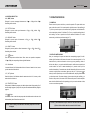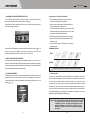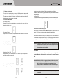
1
TANDA
C Autoclave
Operation Manual
European B Class
Sweden Sino Trading AB
Address Mölndalsvägen 22, 5 tr
41263 Göteborg, Sweden
Website: www.kosmetisk.se
Mob: 073-5543108
Fax: 031-401955
Email: [email protected]
OPERATION MANUAL
Dear Customer
Table of contents
1. We appreciate your confidence to our products and hopes that the performances of
the equipment are full of satisfaction.
2. Please read the instructions of this manual carefully in order to install the equipment and
Operate the equipment in an efficient manner.
3. Please according to operation regulations and keeping keep the sterilizer in a good
Maintenance.
4. Please contact franchiser if you confront with problem when operate the machine, we
ensure quality service and customer support to you.
5. We implement the sustainable developmental strategy. Therefore we reserve
the right to make changes and improvements to any of the products described
in this manual without prior notice.
6. The sterilizer is a device intended for sterilization of non-wrapped, wrapped
and packed instruments, porous loads, and hollow instruments. This device is
designed for use in first aid rooms, dental clinics, operation rooms veterinary
clinics, pharmaceutics industry, removal of medical waste, laboratories etc.
7. The most efficient sterilization of microorganisms is performed in an
environment in which the temperature, the humidity and the process time are
controlled and monitored in the adequate levels.
8. The sterilizer fulfils these conditions. The dry saturated steam in the chamber
provides the temperature and humidity (the pressure enables maintaining the
required temperature and humidity simultaneously)
1. EXPLAINS OF SYMBOL
1
1.2 CONFORM USE
9.2 DAILY MAINTENANCE
2. GENERAL RECOMMENDATIONS
SAFETY
2
3. UNPACKING
3
4
11. DELIVERY AND STORAGE
4.2 ELECTRICITY SUPPLY
5
Above sterilizers accord with the requirements of European Class B:
93/42/CEE
97/23/CEE
EN13060:2004
EN610610-1
EN610610-2-041
EN610610-2-040
5.3 MAIN TECHNICAL SPECIFICATION
12. ELECTRIC AND HYDRAULIC
6. PANEL AND FUNCTIONS
8
DRAWINGS
21
12.1 HYDRAULIC DRAWING
6.1 DISPLAY WINDOW
12.2 ELECTRIC DRAWING
6.2 CONTROLLING BUTTON
10
7.2 DISTILLED WATER ADDING
RESERVOIR IS FULL
7.4 SELECTING STERILIZINGP ROGRAM
7.5 LOADING INSTRUMENT
7.6 CLOSING THE DOOR
7.7 STARTING A WORKING CYCLE
7.8 END OF THE STERILIZATION
WORKING CYCLE.
7.9 POWER OFF
15
8.1 PLEASE ENSURE THE FOLLOWING
8.2 AND PLEASE DO NOT
11.3 CONDITION S FO R STERILIZER'S
TRANSPORTATIONANDS TORAGE
5.4 THE STERILIZATION CYCLES
8 ESSENTIAL INFORMATION
20
11.1 PREPARATION BEFORE
11.2 DRAINING
5.2 REAR VIEW OF THE sterilizer
7. OPERATION PROCESS
20
TRANSPORTATION AND STORAGE
5.1 FRONT VIEW OF THE sterilizer
pic 6-1
10. S
. ERVICING BY THE APPROVED
TECHNICIAN
4.1 INSTALLATION
5. DESCRIPTION
OFTEN IF NECESSARY)
9.4 MONTHLY MAINTENANCE
REQUIRED
3.2 UNPACKING THE ACCESSORIES
4. SET-UP
9.3 WEEKLY MAINTENANCE (MORE
9.5 MAINTENANCE TO BE DONE AS
3.1 UNPACKING THE sterilizer
7.3 ALARMING IF USED WATER
The content of this instruction is fit for sterilizers.
16
9.1 MAINTENANCE SCHEDULE CHART
7.1 POWER ON
DECLARATION OF CONFORMITY
9 MAINTENANCE
1.1 RECOMMENDATIONS-SAFETY
13. THE STANDARDS OF T ESTING 23
OPERATION MANUAL
1. EXPLAINS OF SYMBOL
2. GENERAL RECOMMENDATIONS SAFETY
1.1 RECOMMENDATIONS-SAFETY
1 The user is responsible for operation and servicing the sterilizer in accordance with
The purpose of this user manual is to provide you with all the information you need
the instructions listed in this manual.
in order to ensure.
2 The sterilizer has not been designed for the sterilization of liquids.
A proper installation and set-up
3 The sterilizer has not been designed to operate in the presence of gas or explosive
Optimal use
vapors.
4 The trays and the load will still be hot at the end of each cycle. Use the tray holder to
A safe and reliable operation
Regular and correct servicing requirements
remove each tray from the chamber.
5 Do not open the door of the chamber when you are running the sterilization
The sterilizer is purposed-design for: the steam sterilization of solids, textiles and
hollow items unwrapped, single or double wrapped.
programs.
6 Do not put you hands or face on the cover of the water tank when the sterilizer is
Running.
1.2 CONFORM USE
7 Do not remove the instruction plate or any label from the sterilizer.
8 Do not pour water or any other liquid over the sterilizer.
This symbol draws attention to the user manual.
9 Do not fill the caustic liquid into the water tank.
10 Do not fill the caustic matter in the chamber.
To disregard the instructions which are explained in this manual,
the incorrect use and the unauthorized disassembly to the
sterilizer that indicates the manufacturer, we do not have the
responsibility for warranty a nd a ny o ther c laims.
11 Use only high quality distilled water.
12 Unplug the mains lead before inspecting or servicing the machine.
13 Only an approved technician using original s pare parts c an c arry out repairs and
Maintenance.
14 In case of transport, drain both water tanks completely, allow the sterilization
chamber to be cooled down and preferably use the original packaging.
15 The goods to be sterilized could be picked-up by special handle of getting plate
when the temperature shows under 100 C.
This symbol is visible side cover of the water tank on the
front of the panel after opening up the door.
16 Picking-up the sterilizing plate should use the special handle provided by this
It draws your attention to pay on the high temperature
associated with the chamber, and the sterilizer steam draining
From the cover when it is running.
17 During the transport, the 4 bottoms of s terilizer s hould be raised by two men in
sterilizer.
case of turning over.
18 Notice! This product c an't be put on the place that is not easy to c ut off power
supply.
19 Prohibit covering the cover of water tank when using.
This symbol is grounding protection inside the sterilizer.
-1-
Caution: Comply with the instructions in this manual for ensure safe
operation.If user don't operate according to the instruction, the
security of product in the process of use will greatly be reduced.
And we won't refund the kickback.
-2-
OPERATION MANUAL
3. UNPACKING
4. SET-UP
The sterilizer, the accessories, the user manual and the warranty card are supplied in a
sturdy box.
4.1 INSTALLATION
Check the condition of the packaging on receipt. Contact the carrier immediately and
inform your supplier if the outer packaging is damaged.
3.1 UNPACKING THE sterilizer
The sterilizer has been calibrated and tested in the factory. It does not require
calibration during installation.
Install the sterilizer as outlined below:
v Install the sterilizer on a flat and level surface.
L
v The MAX weight of the sterilizer with the water tank full and the chamber fully
loaded is: 48Kg / 75Kg.
W
v Leave a gap of 15 cm at the back and 10cm on each side of the sterilizer to ensure
adequate ventilation.
+55
_ 40
RH
10%-85%
H
v Do not place the sterilizer near a sink or in a location where it is likely to be
splashed.
v Install the sterilizer in a well-ventilated room.
v Keep away from all sources of heat.
v The above of the sterilizer should be reserved needed space when adding
water,>30cm.
v Notice! This product can't be put on the place that is not easy to cut off power
supply.
18liters
L*W*H=633*500*437(mm)
4.2 ELECTRICITY SUPPLY
23liters
The electrical installation must comply with the current standards in the country.
L*W*H=743*500*437(mm)
3.2 UNPACKING THE ACCESSORIES
Open the door and remove the accessories from the sterilization chamber.
Check the contents:
NO: 1
Anodized aluminum trays
3 sets
NO: 2
Tray removal tong
1 piece
NO: 3
Draining tube
1 piece
NO: 4
Power supply cable
1 piece
NO: 5
Door gasket
1 piece
NO: 7
Tray holder
1 piece
NO: 8
Operation manual
1 book
-3-
-4-
OPERATION MANUAL
5.2 REAR VIEW
USE CONDITION:
Power supply:230VAC 50Hz
Power supply electric current:10A
Ambient temperature:5
40
Relative humidity: 85%
Atmosphere pressure:860Hpa 1060Hpa
12
An earth connection is essential
Caution: The sterilizer must be connected to an electrically earthed plug. Used
15
13
16
only the mains cable delivered with the sterilizer.
14
5. DESCRIPTION
5.1 FRONT VIEW
Steam Sterilizer
12 Fan
15 Nameplate
13 Printer Port
16 Relief Valve
14 Electrical Outlet
Nameplate:
The sterilizer model
Nameplate serial number
The sterilizer code and year
The sterilizer's type
The chamber's capacity
Power/ Voltage/ Current/ Frequency
Company name and address
EC-Representative name and address
sterilizer chamber:
Material: stainless steel (for medical)
1 Filling Water Port(manually)
7 Power Supply Switch
Max. Work Pressure: 2.5 bar
Min. Work Pressure: -0.9 bar
2
Drainage Port(For Used Water Tank)
8 Displaying Window
3
Filling Water Port(Automatically)
9 Alert slogan
4
Drainage Port(For Main Water tank)
10 Door Handle
5
Operation panel
6
Fuse
Max. Temperature: 145
Chamber volume:18L ( 245
320mm) 23L ( 245
sterilizer steam safety valve:
Safety release pressure: 2.45 bar
Max. Working temperature: 160
-5-
-6-
450mm)
OPERATION MANUAL
5.3 MAIN TECHNICAL SPECIFICATION
1) Inner capacity: 18L Ö245mmX352mm
23L (Ö245
450mm)
2) Rated Voltage: AC220V~230V,50Hz
3) Rated power: 1500VA
4) Pressure/Temperature: 0.90 1.30bar/121
~122
2.00
2.30bar/134
1-2 pre-heating
2-3 pre-vacuum
3-4 sterilizing
4-5 air-discharging
5-6 drying
6-7 stabilizing
1-7 entire duration
~135
5) Fuse: T10A
6) Water storage tank capacity: 4L must use distilled water. And water temperature
must under 40
TableTypes of sterilization cycles
Type
7) Water volume for one cycle: 0.16L min
0.18L
max
8) Operation temperature: 5 40
9) Outside size:18Liters,441mm width
23liters, 441mm width
10) Net weight: 18L,47KG;
X389mm
X389mm
height
height
B
The sterilization of all wrapped or non-wrapped, solid, hollow load products
type A and porous products as represented by the test loads in this standard.
S
The sterilization of products as specified by the manufacturer of the sterilizer
including non-wrapped solid products and at least one of the following: porous
products, small porous items, hollow load products type A,h ollow l oad products
B, single wrapped products, multiple-layer wrapped products.
X567mm(depth)
X667mm(depth).
23L,55KG
2
11) The board affording weight:4000 N/m
12) Noise:<45db
Description of intended use
NOTE 1 The description identifies ranges of products and test loads.
13) Available space, size and capacity:190mmX190mmX310mm 12L
NOTE 2
14) The maximum capacity of a plate:1000g
Non wrapped sterilized instruments are intended either for immediate use or for
non sterile storage, transport and application (e.g. to prevent cross infection).
15) Water storage tank cleaning and the frequency of water adding: clean the water
storag e tank once per half a month, you need to add fresh water after every 20
6. PANEL AND FUNCTIONS pic 6-1
cycles generally.
16) The frequency of water draining: once a day, drain the water once you find waster
(Pic6-1)
6.1 DISPLAY PANEL
6.1.1 Pressure display
water over during operation.
Indicate current chamber pressure during a cycle. Unit is bar.
17) The maximum duration of using loading test: 60min.
Bar
18) The maximum thermal radiation energy under the condition of 20 ~26
:<2000J.
6.1.2 Temperature display
o
C
Indicate current chamber temperature during a cycle. Unit is
5.4 THE STERILIZATION CYCLES
6.1.3 Phase/ Error cord display
2.0
Min
NUDE
COTTON
PACKAGE
PLASTIC
Indicate the kinds of phase for sterilizer during operation, refer
to the appendix ( Operation Phase Chart ). When the sterilizer
1.0
begins to alarm, a corresponding error code will be displayed.
0.5
Check the malfunction parts according to the alarm cord and
Pressure
handle form. (When it goes wrong, please contact with the repair
0
Time
shop or dealer promptly)
3
4
-7-
5
6
IN
134 oC
OUT
START&STOP
-1.0
1 2
121 oC
7
-8-
OPERATION MANUAL
6.2 CONTROLLING BUTTON
6.2.1 NUDE button
Designed for process unwrapped instruments at 121
Illuminating when selected.
6.2.2 COTTON button
Designed for process cotton yarn instruments at 121
Illuminating when selected.
7. OPERATION PROCESS
or 135
, default 135
.
7.1 POWER ON
Please connect the power cord before you start the operation. The power switch turns
power to the unit on and off. It is located under the right front corner of the sterilizer (pic
or 135
, default 135
.
7-1). When you turn the power on, the sterilizer is at originally state. It will indicate LD
on the state display window. If it indicates Do , even you push the starting button it
won't working. You have to open the door first, the window will indicate
6.2.3 PACKAGE button
Designed for process packs of instruments at 121
Illuminating when selected.
or 135
, default 135
which
.
Fuse
6.2.4 PLASTIC button
Designed for process plastic or rubber instruments at 121
Illuminating when selected.
LD
means ready, and then keep on the next step (pic 7-1)
or 135
, default 135
Power switch
.
(Pic7-1)
O
C Button
6.2.5
Press the temperature selection button. When selects two operation temperature:
121 or 135 , the corresponding indicator light will illuminate.
7.2 DISTILLED WATER ADDING
After you connecting to the power and select the corresponding program, if the IN
indicator light illuminates, which means the water in the water storage tank is of its
lowest level and you have to add water in. And even you press
6.2.6 IN indicator
Low water indicator, it will illuminate when the level of reservoir water is too low, to warn
you that water should be added in.
start/stop
button, it
will not work either, so you need to add distilled water in until the lowest required level
can be reached. You can fill in water automatically or by manual on the top of the
machine. Automatically: Connect the water tube with the machine left lower corner inlet
connector as right picture arrow marked, please see the pic 7-2. And press
6.2.7 OUT indicator
Water full indicator, it will illuminate when the waste water level is full, to warn you that
water should be drained out.
button; by manual: open the top cover and fill in distilled water, stop filing water in when
you hear beep sound. If the water shortage gives an alarm during the sterilizing, you
should not worry about it, the water will not influence this process. And the adequate
water should be left in the tank for the operating cycle, but you need to add water in time,
6.2.8 START/STOP button
When pressed it, initiates the program cycle that has been selected. Keep pressing it for 5
seconds during a program cycle any time, the cycle will be terminated absolutely during the
progress.
6.2.9
Button
Self-fill button. Press to start the water pump when the sterilizer needs to add water. And
will automatically shut-off when the reservoir is full.
so as to ensure the next operation.
(Pic7-2)
Caution: (1) Use distilled water only to extend the life time of the machine.
Caution: Please contact your distributor or authorized people when error code
displayed.
-9-
(2) Do not ti t the sterilizer when the reservoir is full of water.
-10-
OPERATION MANUAL
7.3 ALARMING IF USED WATER RESERVOIR IS FULL
Arrangement on Trays before Sterilization
The IN indicator light illuminates during the sterilizing, which means that the used
1 Read the following instructions for proper usage and
maintenance of instruments and material.
water storage tank needs to be drained because of full enough.
Connect the water tube to the machine left lower corner inlet connector as right picture
2 Make sure that the instruments of different materials are
Separated and placed on different trays.
arrow marked, please see pic 7-3.
3 In case of carbon steel instruments, place a towel or paperwrap between the tray and the instruments in order to avoid
direct contact between different materials.
4 All the instruments must be sterilized in an open position.
5 Make sure that the instruments remain apart during the
sterilization cycle.
(Pic7-3)
6 Do not overload the trays in order foe items to be properly
Sterilized & dried.
Water has been drained when it reaches the maximum temperature, nearly 70
if it is
DRAWINGS EXPLAIN:
higher, you need to check whether the fan operates normally, or contact the local
distributor immediately, we will offer our best service to you in no time.
RIGHT
7.4 SELECTING STERILIZING PROGRAM
Select the required sterilization program and temperature which you need. When you
choose, the corresponding indicator light will illuminate. After the sterilization program being
UNRIGHT
selected, the temperature will be automatically set as default model. It is recommended that
should not be changed except for special processing.
7.5 LOADING INSTRUMENT
Caution: Recommended to clean the instruments before loading.
7.6 Closing the door
Sterilizing instruments should be put in the instrument plates, there should be left some
gap between each instruments so that the steam can be ventilated freely. Please use
the attached hands clip to send the instrument plates into the sterilizing house to avoid
scalding . pic 7-5
Close the door after loading the instruments which need to be sterilized.
LD
will be
showed and will be not appeared anymore once latch the door handle fully. When close the
door, however, the chamber is warm and steam still be left in it, you may feel a strong
resistance when you close the door. You just have to push harder and latch the handle
completely. You may also leave the door open to release the steam and kindly close the
door again. Or you can push the door in while you turn the door handle. Anyway, latch the
door handle completely If you still unsure the door has been closed properly. You can also
adjust the door (refer to adjusting the sterilizer door)
(Pic7-5)
-11-
Attention: The LD code will be appeared if the door hadn't been closed fully,
the sterilizer will not run unless the door has been closed
completely. If the door has been opened during the cycle, the
sterilizer w ill display error code E6 . If so, please press the
Start/Stop to ca ncel the alarm, Then close the door co mpletely
and restart.
-12-
OPERATION MANUAL
7.7 Starting a working cycle
The door is closed completely, then you can press Start/Stop button to start a working
cycle. The sterilizer will heat and sterilize and drying the instruments automatically for you.
The whole process will take 20-50 minutes. It depends on the object being sterilized, the
initial temperature, and the program you selected.
Display dry-vacuum time and the temp. Draining used water and steam. Sterilizer will
automatically switch to vacuum drying process after the steam pressure drop and chamber
temperature down,
End: Display ED.
The buzzer make a sound means the total sterilization processes have been finished, then
wait for the pressure down to 0 bar at the steam manometer on command front panel.
The Process of Sterilization
Pre-heating: Display HE.
0.0
87
ED
Chamber will start to be pre-heating when you are turning on the power switch, and
keeping the chamber warm.
Pre-vacuum: Display -P.
0.0
--HE
7.8 End of the sterilization working cycle.
When working cycle has been finished, the ED will illuminate and give you a sound of
alerting. Then you can open the door and take the sterilized instruments out.
Outputted the airs in the chamber, and inputted steam in the chamber, run 3 cycle times.
When the door of sterilizer has been opened, the program of digital model will return to
-P
--Po
the initial state, heat-preserving and waiting for next sterilizing program, before start a
new program it will be kept in a heat-preserving condition all the while.
Heating: Display HE.
Attention: After sterilizing has been finished, please use the matched instrument
hand clip to take the instrument plates out from sterilizing house. It will
be better to take out the instrument plates when the instruments have
been cooled down to avoid scalding.
Keep heating until getting the time of sterilization.
0.5
106
HE
7.9 Power off
Sterilization: Display TIME.
When won't use the sterilizer, turn off the power switch, the power switch light will be
Display sterilizing time and temperature. The sterilizer keeps the temperature of
turned off. When the sterilizer hasn't been used for a long time, unplug the power
sterilization with time is counted down.
cord.
1.1
121
20
2.1
134
4
Vacuum drying: Display PL OR TIME
Releasing pressure until the pressure down to the 0 bar or -P
0.2
95
PL
-13-
-P
86
2
Attention: During the sterilizing, we suggest you that you should use the special
paper which can indicate the effect of the sterilization or sterilization
bag which has the effect indication of sterilization, put them in the
chamber together with the sterilizations in order to ensure reliabilityo f
sterilization.
Warning: When the pressure indicator does not show "0 bar", don't try to open the
door please.
-14-
OPERATION MANUAL
8
Essential Information
9 MAINTENANCE
This product is not the washing / cleaning machine. To ensure the sterilizer continues to
operate correctly it is important to ensure the following points and to carry out the
9.1 MAINTENANCE SCHEDULE CHART
necessary care and maintenance procedures as specified.
Maintenance Required
Person Responsible
8.1 PLEASE ENSURE THE FOLLOWING . . .
Daily
1 You have read and follow these operating instructions.
Clean Door Gasket
User
Clean Chamber
User
2 The load is suitable for sterilizing in the cycle selected.
3 The load can be sterilized at the selected temperature.
Weekly
4 The load has been cleaned.
5 The load has been rinsed thoroughly in clean water prior to sterilization to avoid any
chemical residues left after cleaning contaminating the sterilizer.
6 When placing instruments on trays,ensure that they are placed on the ribs of the tray
(to help drainage),they must not touch each other and must not interfere with other
trays or the chamber above.
Clean Chamber, Trays and Rack
User
Clean Water Draining Filter
User
Monthly
Clean Reservoir
User
7 Only distilled, deionized or sterile water can be used.
Yearly
8 The sterilizer is in a draught free area.
Performance Verification and maintenance
9 The sterilizer is not installed in an enclosed cupboard space.
As Required
10 All other exterior product panels are 50mm clear of adjoining surfaces to allow air
Change Door Gasket
Qualified service personnel
User
Circulation.
11 The door is left ajar when not in use.
12 You quote model/serial number (which are located on the rear case just above the
mains power c ord entry) and date of purchase in all c orrespondence.
13 Only qualified personnel service the sterilizer.
9.2 DAILY MAINTENANCE
Cleaning Door Gasket
The door gasket and the mating surface should be wiped off each day with a clean,
damp cloth. Do not use abrasive cleaners on the gasket or mating surface.
8.2 AND PLEASE DO NOT....
Use warm soapy water for keeping marks of sterilizer persistent, but ensure any soap
1...lose this handbook.
residues are completely removed by wiping both the gasket and the vessel again with
2...add any chemicals or whatsoever analogous water to the sterilizer.
water using a lint free damp cloth.
3...attempt to sterilize volatile substances, toxic materials or other unsuitable loads.
Refer to your " Responsible Person" for advice.
Warning: Refer to qualified personnel for servicing: Never use a wire brush,
4...place the sterilizer in direct sunlight.
5...place the sterilizer on heating sensitive surfaces.
steel wool, a brasive material, o r c hloride-containing p roducts to
6...use inappropriate cleaning materials.
clean door a nd c hamber a ssembly."Caution hot s urface. Avoid
7...drop or abuse the sterilizer.
contact." e nsure that the s terilizer is c ooled down fully before
8...use in areas of risk associated with flammable materials or gases.
cleaning to av oid scalding.
9...remove the casing or attempt to service or repair this sterilizer.
-15-
-16-
OPERATION MANUAL
Cleaning After Liquid Loads
Water draining filter might has been jammed by some dust because of use for a long-
Biological media tends to boil at a higher rate than other liquids during venting; it results in
term, so effect of vacuum and drying would be influenced. Some tiny impurity might be
media to be spattered inside the chamber. Therefore, the chamber must be cleaned daily
deposited on the filter after a long-term use, blocking the filter, so as to influence the
when you are sterilizing media. Cleaning as follows:
effect of the vacuuming and water discharging. The kinds of impurity come from smeary
1
dust on the instruments being sterilized or some calcification in the water.
Allow unit be cooled down.
2 Wipe out chamber and door with a clean, damp cloth.
Keep cleaning of the inside chamber in order to make life-time of filter much longer;
please take the following advice for consideration:
9.3 WEEKLY MAINTENANCE (MORE OFTEN IF NECESSARY)
1 Use eligible distilled water;
Cleaning Chamber, Trays and Rack
2 The instruments should be cleaned before placing in; it is good to use specified
At least once a week, the trays and tray rack should be removed from the sterilizer
chamber. The trays, tray rack and chamber should be thoroughly cleaned to remove
packing for the instruments with oil or other impurity, don't forget to seal up.
3 Keep the sterilizing chamber tidy. Once the water draining filter jammed, the solution
any deposits from the surfaces.
has been showed in pic 9-2, would be recommended. As for the filter's blockage
Clean the trays, rack and chamber (especially the bottom of the chamber) with
you can follow the methods have been showed in pic 9-3, after it cooling down as the
appropriate antibiological cleaners. Wipe all residues from the surfaces with a
picture shows.
dampened, lint-free cloth.
Caution:To prevent from collection of mineral deposits and corrosion of
chamber components, use distilled or deionized water only as
Specified.Clean chamber after each use if sterilizing saline solutions.
(Pic 9-2)
Broiling filter alcohol
(Pic 9-3)
Blow with a high pressure air-pump
Cleaning water draining filter (pic 9-1)
9.4 MONTHLY MAINTENANCE
Cleaning Reservoir
There are some impurities and some toxins had been left behind in the reservoir because
distilled water had left behind for a long time, so you need to drain and clean regularly.
According to the picture which shows below, loose the screw by screw-driver, and open the
cover to clean inside. As pic 9-4 shows
(Pic 9-1)
(Pic 9-4)
Attention: (1) Be sure that use distilled water properly in order to extend the
Sterilizer life-time.
(2) Do not rave about the sterilizer when the tank has been filled.
(3 ) The water in used water storage tank should be drained constantly.
-17-
-18-
OPERATION MANUAL
Do not add more than 7 liters of water to the reservoir after cleaning.
10. SERVICING BY THE APPROVED TECHNICIAN
9.5 MAINTENANCE TO BE DONE AS REQUIRED
Service is essential for consistently effective sterilization.
We recommend servicing by an approved technician every 2 years.
CHECK-LIST:
1 Checking the Electro-valves.
2 Checking the water pump.
3 Checking the vacuum pump.
4 Checking the distilled water drain valve and the used water drain valve.
5 Checking the relief valve.
6 Checking the door locking system.
7 Checking the probe of the pressure and temperature.
8 Checking the probe of the water in the sterilization chamber.
9 Checking the electrical connections.
10 Checking the hydraulic connections.
11 Checking the safety thermostat.
12 Cleaning the sterilization chamber.
13 Cleaning the trays and the tray holder.
14 Cleaning the reservoirs.
15 Replacing the water filter.
16 Replacing the air filter.
17 Replacing the door gasket.
Changing Door Gasket
Tool a plain screw driver without sharp head is needed.
Disconnect the sterilizer from the power supply. Ensure that the sterilizer is cool and
depressurized.
1) Hold verge of the seal by one hand softly, and another hand should be inserted the
Screwdriver into the gap between gasket and door, take out the seal slowly.
2) Once you take out one part of the seal, you can draw out the whole seal slowly. After
taking out the seal, please check and clean the groove of gaske t, so does the
gasket,please replace the gasket if there is some damage.
3) Fix the clean gasket in initial door groove. Attention: the gasket should be imbedded
in the groove equably. At first, please imbed the 4 spots equably into groove when fix
the gasket, and then embed the other parts. After that, press the gasket equably by
hand.
4) Attention: the inner edge of gasket may be ectropium during embedding it in the door
groove,at this time; you'd better to tight it back to the groove by using the screwdriver
carefully.
11. Delivery and storage
11.1 PREPARATION BEFORE TRANSPORTATION AND STORAGE
Shut off the power switch, unplug the cord, and make the sterilizer been cooled down
completely.
11.2 DRAINING
Drain water from reservoir and the condensate collector completely: insert the joint end of
the attached tube to drain connection. (The spout on the left is the water spout used for
the used-water out , the one on the right is used for the clean-water drain spout)
Used-Water out
-19-
Clean-Water out
-20-
AF
Air Filter
WP1
UMT
The Used Water Tank
WP2
Add Water Pump
DWT
The Distilled Water Tank
SM
Steam Maker
EV1
Air Outlet Valve
VP
Vacuum Pump
EV2
Chamber Water Inlet Valve
CC
Condensate Collector
EV3
Vacuum Valve
RV
Relief Valve
EV4
Drying Air Inlet Valve
R1
Distilled Water Drain Valve
EV5
Drain Valve
R2
Used Water Drain Valve
P1
Pressure sensor
R3
Water Adding Valve
P2
Pressure sensor
Ts1
Temperature Sensor
-21-
ï H2 O
R2
R3
Main Water Pump
-22+Power(L)
-Power(N)
15A fuse
15A fuse
Grounding
Pressure sensor
WP1
Power switch
Sensor detect area
Ev2
outer temp.sensor(TH3)
Sensor detect area
Heating control area
Ev4
Temp.protection sensor
Temp.protection sensor
RV
Inner temp.sensor(TH2)
Motor control area
AC220V output
Chamber heating system
Steam generator
Steam generator water pump
Tank water pump
Vacuum
Fan
Atmospheric pressure: 500HPa~1060HPa
Steam generator temp.sensor
Output to printer
SM
To Db9socket
ñ Air
Output to key board
CC
Switch detect area
AF
To key board
Power filter
ð H2 O
EV1
Door switch
VP
Transformer power
input entrance
12. ELECTRIC AND HYDRAULIC DRAWINGS
Condensed collector water level sensor
WP1
Electromagnetism valve
control output
Ev3
Transformer AC 9V output
P1
Tank water level sensor
R1
TS1
Air outlet valve
DWT
Transformer AC 220V output
12.1 HYDRAULIC DRAWING
Dry ing air inlet valve
Chamber
Transformer AC 21V output
Relative Humidity:
Chamber water inlet valve
11.3 CONDITIONS FOR STERILIZER'S TRANSPORTATION AND STORAGE
Vacuum valve
Temperature: -5
Drain valve
OPERATION MANUAL
~ +55
12.2 ELECTRIC DRAWING
85%
Ev5
UWT
OPERATION MANUAL
13. The standards of testing
NO.
1
Testing item
Shape
2
Outer-veil
3
Letter marker
Request of standards
The shape of sterilizer should be tidiness and
mustn't have the disfigurements, such as deflection,
hollowness, c ollision, nick, s harp edge, and s o on.
The outer-veil should be assured to disassemble
easily in order to repair the equipment.
Electroplate components
The Electroplate should accord with YYOO76-19
92 class 2, which for the request of aspect.
5
Printer components
The Printer components should accord with Yy1055
-1999 the class which for the request of aspect.
6
Door safe lock
On the normal condition, if the sterilizer door hasn't
been locked tightly, the program can not start.
Chamber Pressure
The door should ensure that the door can't be opened
when the chamber pressure over than 0.027Mpa.
Relief Valve
Sterilizer have to install relief valve, when the
pressure range from 0.27Mpa 0.01Mpa that the
relief can be opened, and when arrive at the setting
pressure, the air relief valve will open automatically
and discharge pressure.
8
9
Sterilizing Program
10
Controlling system
11
Timing control
12
Button and Switch
13
14
Indicator and display
Quantum of leak
Testing item
The sterilizer can't leak under the work pressure
16
protective earthing
impedance
17
Successional leakage
current under the
work temperature
18
Dielectric strength
with Working
Temperature
The impedance between p rotective earthing point of
the poweri nput faucet and protective earthing canbe
touched all metallic parts, doesn't over than 0.1Ù.
a) Earth leakage current on the normal condition: <0.5
Ma the single blooey state: <1 mA
b) Crust leakage current on the normal condition: <0.1
Ma the single blooey state: <0.5Ma
a) A-al: It should bear the sine wave tes t alternative
voltage ,50Hz, 1500v, which between the web power
input port and protective earthing can be touched al l
metallic parts.It lasts1 min,and hasn't the phenomenon
of breakage and flashover
b) A-a2: It should bear the sine wave test alternative
voltage, 50Hz, 1500v, which between the web power
input portand thee nclosure of which isn't be pretended
earthing. It lasts1 min,and hasn't the ph enomenon of
breakage and flashover
No-load
For all loads except hollow load A, the presence of
saturated steam in the usable space and the load is
deemed to have been achieved when,t hroughout t he
holding time,all temperatures measured in theus able
space and the load: (Attention: the theory of steam
temperature is accounted by measuring pressure,
which can be considered the test temperature.)
are not lower than the sterilization temperature;
are not more than 4 K above the sterilization
temperature;
do not differ from each other by more than 2 K.
The usable place temperature during the no-load can
not over than the scope of highest temperature.
Hollow load
The hollow load A and B,As f or t estifying whether
the saturation steam existing is relevant to the color
change, by distinguish used chemistry direction
system whether it was according to the direction
system manufacture
Sterilizer should have the pre-established program
about 121 C and 135 C, dressing and instruments.
O
O
The control system in sterilizer should limit the steam
which in the chamber be controlled at the highest
average temperature in 3 of pre-establish station.
And ensure the temperature value accords with the
pressure controlling value.
It's possible that the sterilization and drying can be
timing control, and the windage should be limited
that smaller than 10% of pre-establish value.
Buttons and switches should be flexible and
reliable on the sterilizer.
The indicators and displays of sterilizer should show
the states of every sterilizing procedure exactly.
Under the normal situation,sterilizer should i ndicate:
a) Chamber temperature
b) Chamber pressure
c) Sterilizing work state
d) Water level state
e) Station of the opening or closing door
on the condition of the vacuum -0.07 Mpa,th e sterilizer
shouldn't leak 0.013Mpa within ten min.
-23-
Request of standards
Leak forbid
15
The letter marker in panel of sterilizer should be legible.
4
7
NO.
19
20
21
Dryness, solid load,
double wrapped
For wrapped loads, a ny remaining moisture shall not
leadto wet packagesand sha llnotr esult in de trimental
effects on the sterilizer load. Any remaining water
dropletso n thein ner side of the film of laminate pouch
shall evaporate within 5 min.
For load the moisture content shall not exceed 0,2 %
-24-