1
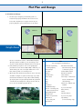
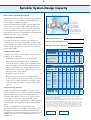
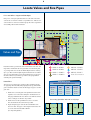
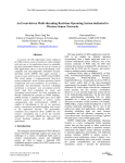
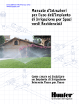
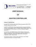
Residential Sprinkler System Design Handbook A Step-By-Step Introduction to Design and Installation T and installing single family residential sprinkler systems. It Table of Contents is set up in an easy-to-follow format with illustrations and Plot Plan and Design................................................................ 1 his booklet is intended to be used when designing helpful charts. If this is the first system you have installed, or if you have installed several systems but have never used this guide before, we recommend you look through the next few pages and become familiar with this presentation of the design and installation process. You will notice we have included a sheet of graph paper for your convenience. There are detailed illustrations depicting suggested installation methods for sprinkler heads, pipe and valve manifolds, and how to connect the sprinkler main line into the house water supply or pump. Installation tips have also been placed throughout the guide to assist you in planning a system. A Glossary of Terms is included and Hunter Sprinkler Performance Charts are featured on the back cover. While developing the Liters Per Minute (l/min), Working Pressure and Pipe Sizing charts, we considered reasonable friction loss and acceptable water velocity for a residential irrigation system. If you have any questions on the design or installation process, your best resource is your local Hunter distributor. Hunter recommends contracting the services of a professional irrigation designer when planning large residential or commercial projects. Contractors and irrigation designers can receive additional information by contacting their local Hunter distributor. Sprinkler System Design Capacity............................................ 2 Service Line Size Chart System Design Capacity Chart Select Sprinkler Heads.............................................................. 3 Locating Sprinkler Heads.......................................................... 4 Divide Sprinklers Into Zones..................................................... 5 Area Capacity Example Locate Valves and Size Pipes.................................................... 6 Pipe Sizing Chart Point of Connection.................................................................. 7 Sprinkler System Overview................................................... 8–9 System Installation............................................................ 10–12 Making the Point of Connection Installing the Main Line Installing the Valve Manifolds Installing the Lateral Lines Installing the Controller Installing Heads Backfilling Materials List..................................................................... 13–15 Glossary of Terms.................................................................... 16 Watering Guidelines...................................... Inside Back Cover 1 Plot Plan and Design A.Plot Plan And Design 1. The first step in designing a residential system is to measure the property and indicate the location of the house. On a separate piece of paper sketch out your property and place your measurements on the sketch. AREA C AREA B AREA D Graph Areas AREA A AREA E Be sure to include all concrete or brick walks and patios, TIPS driveways and fences. While you are measuring, locate Tools and Supplies You May Need any trees, shrubs and lawns and draw them on the sketch. 2. Next, draw the plot plan to scale on the graph paper provided. The scale can be 1:100, 1:200, or whatever you Permit (As required by local/city bylaws) Automatic Drain Valve (Used in freezing climates decide. Write your scale on the plan. Make sure to note Electrical Tape lawn, shrub, ground cover and large trees. Hack Saw Insulated Wire Staples to winterize system) Hammer Rain Shut-off Device should be rectangles or squares and as large as possible. Pipe Wrenches Shut-off Valves Consider the information in Step 2 above while dividing Plastic Sheet Teflon Tape or Teflon Paste up the plot plan: front yard, back yard and side yard, lawn Pliers or shrub areas and shady areas. Label your areas A, B, C, Rags D, etc. (See the example plot plan above). Rake 3. On the plot plan, divide the property into areas. The areas Screwdriver Small Marker Flags Shovels – Trenching, Flat, Spade or Round Point Spray Marking Paint Tape Measure (Used on all thread-tothread fittings) Valve Boxes, 150 mm and 250 mm If you use PVC Pipe: Glue (Solvent) Primer PVC Pipe Cutters Trencher or Pipe-Puller If you use Poly Pipe: Tunnel Kit or Pipe Clamps Hose Jetting Kit Wire Cutters (for insert fittings only) 2 Sprinkler System Design Capacity B.Determine System Design Capacity When planning an efficient automatic irrigation system, you must first determine the correct Sprinkler System Design Capacity – how much water is available for irrigation. To check water pressure, attach a pressure gauge to the outside tap nearest the water meter or water source. A pressure gauge can be obtained from your local Hunter dealer. If the system will be installed using the city water supply, follow steps 1 – 3 below. If the water will be drawn from a lake, tank, bore hole or well, your Hunter dealer or the pump installer will have the specifications for pressure and volume output of your pump. Enter this information in the Working Pressure and Design Capacity boxes at the bottom of the page. 1. Water Pressure (kPa) (Bars) To check the water pressure, attach a pressure gauge to the outside tap closest to the water supply. Make sure that no other water is flowing at the residence. Turn on the tap and record the number in the area provided to the right. This is the static water pressure in kPa or Bars. 2. Water Volume (l/min) To determine the volume of water available for the system, you need two pieces of information: Enter Static Pressure Here: Enter the Size of the Meter Here: Write the Service Line Size Here: service line size APPROXIMATE STRING LENGTH Size of Copper Pipe 7 cm 8.25 cm 20 mm 9 cm 10.5 cm 11 cm 13.5 cm 25 mm 32 mm A. What size is the water meter or water supply line? Size of Galvanized Pipe 20 mm 25 mm 32 mm Water meters will generally have the size stamped on the Size of PVC Pipe 20 mm 25 mm 32 mm meter body. The most common sizes for residential meters are 15 mm, 20 mm, and 25 mm. In some areas the water supply hooks directly into the city main without the use of the water meter. In these cases, simply enter the size of the service line in the space provided. B. What size is the service line? Measure the outside circumference of the pipe that runs Sprinkler System Design Capacity STATIC PRESSURE 2.8 275 3.5 350 4 415 4.8 480 5.5 550 SERVICE LINE MAX l/min MAX l/min MAX l/min MAX l/min MAX l/min MAX l/min 15 mm 13 mm 20 mm 25 mm 7.6 15 15 15 23 26 19 30 30 23 30 38 26 38 49 26 45 57 20 mm 20 mm 25 mm 32 mm 15 19 19 23 26 45 30 38 64 34 53 76 38 64 83 45 76 83 25 mm 20 mm 25 mm 32 mm 15 19 19 26 30 53 30 53 91 34 68 98 45 76 114 45 76 130 1.7 2 2.4 3 3.5 3.8 175 200 240 310 345 380 and use the table to the right to convert the string length to pipe size. 2 200 WATER METER from the city main to the house. An easy way to do that is to wrap a piece of string around the pipe, measure the string, Bars kPa 3. System Design Capacity Using the System Design Capacity Chart on this page, locate the three numbers you just recorded to determine the Sprinkler System Design Capacity in liters per minute (l/min). Record this number in the l/min box. Next, locate your system’s static pressure and move down that column and find the system’s working pressure; record it in the kPa/Bars box. Working pressure will be used when choosing sprinkler heads and designing the system. You have now established the maximum l/min and the approximate working pressure available for the sprinkler system. Exceeding these maximums may result in inefficient watering or a condition referred to as water hammer, which could cause serious damage to the system. These two numbers will be used in the design process. WORKINGBars PRESSUREkPa Service lines are based on 30 meters of thick walled PVC. Deduct 7.6 l/min for copper pipe. Deduct 19 l/min for new galvanized pipe. Working pressure is the approximate working pressure at the head, and should be used only as a guide when choosing the proper sprinkler heads and designing the system. The numbers in the Design Capacity Chart are based on generally accepted flow rates (velocity). In some cases, designers increase the velocity in copper pipe only from the accepted 2.3 meters per second (mps) to 2.75 meters per second (mps). If you do not deduct the 7.6 l/min for copper pipe, the rate is approximately 2.7 meters per second (mps). The friction loss is substantially increased at this speed, and the working pressure will be affected. In order to use numbers in the chart, the length of copper service line should not exceed 15 meters if you decide not to deduct the 7.6 l/min. l/min Design Capacity BarskPa Working Pressure 3 Select Sprinkler Heads C.Select Sprinkler Heads There are three basic types of sprinklers for residential use: large area rotors, rotating stream spray sprinklers and small area fan spray sprinklers. Large area rotors and rotating stream spray sprinklers should never be installed on the same zone as small area fan spray sprinklers. High efficiency spray nozzles such as Pro-Spray® MP Rotators® should be AREA B considered in place of traditional spray nozzles. AREA C AREA D Locate Sprinklers AREA A AREA E 1. Large area rotors will cover areas that measure 8 meters by 8 meters and larger. 2. Small area sprays are typically used in areas smaller than 8 meters by 8 meters. Within both of these groups are pop-up sprinklers which are installed even with the ground level, and riser-mounted shrub heads, which are installed above ground level. This 8 meters by 8 meters measurement is not a hard rule, rather it is a guideline. The only consideration restricting the size of the area in which spray heads (small area sprinklers) can be used is economics. If a large area or mid-range rotor can be used, it usually means less pipe, fewer valves and a smaller controller will be required to complete the job. Pro-Spray® – Small Area Spray 3 meters to 5 meters spacing PGJ – Mid-Range Rotor 5 meters to 11 meters spacing PGP® – Large Area Rotor 8 meters to 12 meters spacing I-20 – Large Area Rotor 8 meters to 12 meters spacing EXAMPLE System Design Capacity ◗ Water Meter 15 mm ◗ Service Line 25 mm ◗ Static Pressure 4.8 Bars, 480 kPa According to System Design Capacity 49 l/min 3.5 Bars, 345 kPa Design Capacity Working Pressure Pro Spray® – MP Rotator® from a 4’ strip to a 30’ radius 4 Locating Sprinkler Heads D.Draw Sprinkler Locations Decide where you will be installing large area sprinklers and where you will be installing small area sprays. Large area sprinklers should be 8 meters to 12 meters apart. Small area sprays should be 3 meters to 5 meters apart. This spacing will allow sprinklers to overlap their throw to assure even water distribution. Do not mix sprinkler types within one area. Do not place sprinkler heads too far apart; stay within specifications listed on the Sprinkler Performance Charts on the back cover. Spacing is determined by the size of the area the sprinkler is serving. Additionally, a sprinkler should be spaced so that it will spray both the head next to it and the head across from it. Working with one area at a time, start placing sprinkler heads: Step 1 Corners are critical points. Start by placing sprinklers in each corner. Step 2 Add sprinklers along the sides if necessary. Step 1. The critical points on a plan are the corners. Draw a quarter pattern sprinkler in each corner. Using a compass, draw an arc showing the sprinkler’s watering pattern. Step 2. If the quarter heads will not spray each other (head-to-head spacing), place heads along the perimeters. Draw these sprinklers’ watering patterns. Step 3. Now look to see if the perimeter heads will be spraying across the area to the heads on the other side. Step 3 Larger areas may require sprinklers in the middle, in addition to the sides, in order to provide head-to-head or overlapping coverage. If they do not, add full circle heads in the middle. An easy way to locate these heads is to draw perpendicular grid lines from one perimeter head to another. Again, using the compass, draw an arc showing this sprinkler’s watering pattern to make sure there is complete coverage. Curved Areas Convert curved areas to a series of straight lines; place sprinklers the same as you would in square or rectangular areas. Adjustable arc nozzles on spray heads work very well in curved areas. Tip Check with local agencies: • To find out if a permit is required before installing a sprinkler system. • To determine where gas, telephone and other utility lines are buried. • To find out which type of backflow preventer is required in your area. 5 Divide Sprinklers Into Zones E. Divide Areas Into Zones Unless you have a very small yard, you probably do not have enough water capacity to irrigate the entire yard at once. Many areas will require more water than the residence has available (system design capacity). Area C Area B Area D Indicate Zones Area A Area E You will need to section the yard into “zones.” Dividing the area into zones is an easy process. Beginning with area A: ÷ = 1. Refer back to the working pressure entered on page 2. This is the pressure you will need to use when determining sprinkler spacing and l/min requirements listed in the Total l/min of all heads in one area Design capacity in l/ min (from page 2) Sprinkler Performance Charts. Area Capacity example 2. Write the individual sprinkler’s l/min next to each sprinkler head in the area. Use the Sprinkler Performance Charts on the back cover. 3. Add up all of those numbers and divide the sum by the total l/min (system design capacity) available. Number of zones in this area Area Area l/min ÷ Design Capacity A 32 ÷ 49 = Round up for Number of Zones = 1 B 51 ÷ 49 = 1 4. If the total number of zones is not a whole number, round C 69 ÷ 49 = 2 the number up to establish how many zones there will be D 62 ÷ 49 = 2 (1.2 zones becomes 2 zones). This is the total number of E 39 ÷ 49 = 1 valves needed for the sprinklers in that area. 5. Now that you know how many zones the area will have, divide up the sprinklers so that each zone in the area will have approximately the same l/min. Do not place too many heads on the same zone; stay within the system’s design capacity. 6. Draw and label the zone valves for this area, i.e. Zone 1, Zone 2, etc. 7. Follow the above procedure to locate sprinklers and divide all areas into zones. Area C = 68.7 l/min PGJ Mid-Range Rotors 6 Locate Valves and Size Pipes F. Locate Valves • Layout and Size Pipes Every zone on the plot plan must have its own valve. The valve controls the on-off flow of water to a sprinkler zone. Indicate one control valve for each zone and then group the valves together in an assembly called a valve manifold. Area B Area C ZONE 3 ZONE 4 ZONE 5 ZONE 6 ZONE 2 Area D Valves and Pipe Area A ZONE 1 Determine where you want the valve manifold for each area. You may want a manifold in the front yard and one in the back yard, or you may want more locations. Manifold placement is entirely up to you. We recommend placing the manifold in an accessible spot for easy maintenance. Place the manifold close to the area the valves will serve, but where you will not be sprayed when activating the system manually. ZONE 7 Area E area a – zone 1 area d – zone 5 area b – zone 2 area d – zone 6 area c – zone 3 area e – zone 7 area c – zone 4 Point of Connection Lateral Line The two most common types of pipe used in sprinkler systems are polyvinyl chloride (PVC) and polyethylene (Poly). Check with your local Hunter dealer to find out which type of pipe is used in your area. 1. Draw a line connecting all of the sprinkler heads in each separate zone. Follow the example in the illustration on Pipe Sizing Chart Maximum Flow Rates for Sprinkler Lines Pipe Sizes PVC Thick Wall PVC Thin Wall Polyethylene Pipe 20 mm 34 l/min 38 l/min 30 l/min 25 mm 57 l/min 60 l/min 50 l/min 32 mm 91 l/min 99 l/min 83 l/min this page and draw the most direct route with the fewest turns or changes of direction as possible. 2. Draw a line from the sprinkler line to the zone valve. Connecting Sprinklers with PVC or Poly Pipe This should be the most direct line possible. 3. Begin sizing the pipe. Start at the head farthest from the zone valve. The pipe connecting the last head to the OR OR Right Wrong second to last head should be 20 mm. (See Pipe Sizing Chart.) 7 Point of Connection 4. Add the l/min requirements of those two heads together to size the next pipe. 5. Add the l/min requirements of the next head to the previous total. 6. Continue to do this until you get to the zone valve. Be sure not to size a pipe smaller than the chart indicates. 7. Repeat Steps 1 through 6 for each zone. Main Line 1. Determine the location for the system point of connection. It should be near the water supply. 2. Draw a line connecting all the manifolds together, and then draw a line connecting this line to the P.O.C. 3. The main line should be one pipe size larger than the largest lateral line. G.Point Of Connection (P.O.C.) P.O.C. to city water supply: Use a brass compression tee to connect your sprinkler system to the household water supply. Connecting to City Water Supply Use a brass compression tee to hook your sprinkler system to the household water supply line. You may hook up to copper, PVC or galvanized iron service lines without having to solder or thread any pipe. Most areas require some type of backflow preventer to protect drinking water. Copper pipe may be required between the P.O.C. and the backflow preventer. Always check the local building code or with the local permitting agency for the requirements in your area. Connecting to City Water Supply in Freezing Climates If the installation is in a freezing climate and the P.O.C. is in the basement, install a drain valve immediately after the isolation valve to drain the irrigation line before first freeze. Connecting to a Pump When the water source is a tank, lake, well or bore hole the irrigation system is usually pressurized by a pump. A foot valve may be installed at the inlet of the suction line to keep the pump primed. A check valve should be installed on the discharge line to prevent backflow. A manual control valve should be installed in the discharge line to regulate flow and a pressure gauge should be used to monitor dynamic system pressure. Try to minimize elbows, bends and other causes of turbulence and friction in the suction and discharge lines. P.O.C. freezing climate Tips Most professional installers recommend PVC pipe for the constant pressure line from the backflow Review Design preventer to the zone control valves. Some The design process is now complete. Check to make sure you have placed sprinklers in all areas. Also, review the pipe layout to be sure you have sized the pipe correctly. You are now ready to begin installing the system. local ordinances before laying out your system. communities require copper, however. Check AUTOMATIC SPRINKLER CONTROLLER X-CORE GEAR DRIVEN RO I-20 SMART CONTROL WIRELESS SOLAR SYNC RECEIVER 3/4” REMOTE CONTROL ROAM RECEIVER SWING JOIN SJ SERIE PVC EL OR POLY ELL (IN PVC (POLYVINYL CH OR POLY (POLYETH SPRINKLER CONTROLLER WIRE LOW VOLTAGE WATERPROOF WIRE CONNECTORS CAP FOR FUTURE USE ACCUPRESS VALV AUTOMATIC C PGV SERIES MALE ADAPTO VALVE BOX BRASS GATE VALVE OR BRASS BALL VALVE POINT OF CONNECTION ( P.O.C ) REMOTE CONTROL ROAM TRANSMITTER OTORS 0 ULTRA NT ES LL (SLIP THREAD) NSERT X THREAD) PVC TEE (SLIP X SLIP X SLIP) OR POLY TEE (INSERT X INSERT X INSERT) NOZZELS MP ROTATOR® SERIES HLORIDE) PIPE HYLENE) PIPE SPRAY SPRINKLERS PRO-SPRAY® PRS-40 SERIES 1/2” SWING JOINT SJ SERIES PVC REDUCING TEE (SLIP X SLIP X THREAD) OR POLY REDUCING TEE (INSERT X INSERT X THREAD) -SYNC 50 AUTOMATIC SURE REGULATOR SMART CONTROL WIRELESS SOLAR SYNC TRANSMITTER VE BOX CONTROL VALVE ORS Hunter Sprinkler System Overview 10 System Installation H.System Installation Making the Point of Connection to City Water Supply 1. Refer to the Point Of Connection (P.O.C.) detail on page 7. 2. Turn off the water supply to the residence. 3. Dig a hole to expose the supply line. 4. Cut a 25 mm piece out of the supply line, slip the compression tee onto the pipe, and tighten the compression nuts. 5. Install the brass nipple and gate valve. 6. Install the valve box for easy access to gate valve. 7. Turn the water back on to the residence. Before trenching, use small flags and marking spray paint to lay out the irrigation system. Installing the Main Line 1. Using marking spray paint, indicate the pipe lines from the pump or the P.O.C. to the valve manifold locations. 2. On existing lawns, lay down a plastic tarp alongside the marked trench about 60 cm away from where the pipe will be placed. 3. Remove the sod by cutting a strip about 30 cm wide and 4 cm to 5 cm deep using a flat shovel. Roll up the sod and place the sod and dirt on the plastic tarp. 4. Trenching: Check local codes. If there are no established local codes for sprinkler main line depth in your area, trench 25 cm to 30 cm deep. 5. Installing Pipe Under a Walkway or Driveway: Hammering Method: Cap off both ends of a galvanized pipe and hammer through (See illustration). Jetting Method: Using a pipe-to-hose threaded adapter, connect one end of the pipe to a garden hose and attach a small stream hose nozzle to the other end. Turn the First lay down tarps and remove sod, then dig trenches 25 cm to 30 cm deep for the main line. Trench 15 cm to 20 cm for lateral lines. water on and jet under the concrete. 6. Install a backflow preventer where required by local municipal codes. 7. Installing Pipe: Lay out pipe and fittings near the trenches according to how they will be installed. Be careful not to get dirt or debris in the pipe. 8. Beginning with the P.O.C. (or backflow preventer if applicable), measure, cut and install the pipe, working your way to the last manifold or stub-out. (See Sprinkler System Overview on pages 8 – 9.) 9. Backfilling the main line is discussed on page 12. Connect pipe under a walk or driveway by capping off the ends of galvanized pipe and “hammering” through. 11 System Installation Installing the Valve Manifolds 1. Refer to the valve manifold detail on the Sprinkler System Overview. 2. Maintain at least a 15 cm clearance between valves for future maintenance. 3. Provide a 8 cm long or longer capped stub-out for future additions. 4. Install the valve manifolds onto the main line. Assembling PVC: 1. Place solvent on inside of fitting and outside of pipe. PVC: 2. Slip pipe into fitting and wipe off excess solvent. 5. Installing the valve boxes is discussed on page 12. Installing the Lateral Lines If you can only devote a day or two at a time to installing this system, and the installation is in an area that is currently landscaped, lay out all zones and install one zone at a time using the following steps: 1. Lay Out System: Using the plot plan and small sprinkler flags, mark the location of the sprinklers and their zone valve. Make adjustments as necessary for complete Assembling Poly Pipe: 1. Place clamp over pipe, then insert barb fitting. Poly Pipe: 2. Tighten clamp around pipe and fitting. head-to-head coverage. If it appears that you will need to revise the plan (add a head), recheck the l/min numbers to make sure you are within the system’s design capacity. (See page 5.) Recheck the Pipe Sizing Chart to make sure the change will not affect the pipe sizes designated. (See page 6.) 2. Using marking spray paint, mark the locations for the lateral lines. 3. Trenching: Check local codes. If there are no established codes for sprinkler lateral line depth in your area, dig the trenches 15 cm to 20 cm deep. If you are installing poly pipe, you may want to use a pipe puller. 4. Installing Pipe: Lay out pipe and fittings at the side of the trenches according to how they will be installed. Be careful not to get dirt and debris inside the pipe. Lay out the pipes and sprinklers near the trenches where they will be installed. 5. Backfilling the lateral line is discussed on page 12. Tips Most professional installers recommend PVC pipe for the constant pressure line from the backflow preventer to the zone control valves. Some communities require copper, however. Check local ordinances before laying out your system. Automatic Drain Valve Installation for Freezing Climates: Locate the drain valves at the low points in each zone. 12 System Installation Installing the Controller 1. Decide where you would like to locate the controller. Most residential controllers should be installed indoors. Follow the installation instructions that come with the controller. You will need a 220–240V or 115V electrical outlet to plug in the low voltage transformer. 2. Use color-coded irrigation wire to connect the valves to the controller. The total number of wires you need is one for each of the valves, plus one common wire. If you are wiring a 5-zone system, purchase a combination of wires with at least 6 total wires long enough to reach from your controller to the farthest valve. 3. Installing Wire: Lay the wire in the trench from the controller to the valve manifolds. It is best to protect the wire from future digging by installing it directly beneath Use color-coded irrigation wire to connect the valves to the controller. You will need one wire for each valve, plus one common wire. the pipe where possible. Leave an expansion loop of wire at each change of direction. The loop will ensure that the wires will not be installed too tightly and will reduce the possibility of stretching. 4. Connect the wires to the valves with waterproof connectors. You will need one wire for each valve, plus one common wire which will be connected to one of the wires on all of the valves. Roam Remote Control Kit The Hunter Roam Remote Control Kit saves time during installation and routine system maintenance. The receiver (left) plugs into the Controller Connection Kit and the transmitter (above) activates the sprinklers within a 1,000' range. The user can manually run any zone without resetting the controller. Installing Heads 1. Install all the heads but the last head on a run. Leave the last one(s) off for proper flushing. 2. Flushing System: Turn on the zone manually at the valve. Allow the water to flush out any dirt which may have entered the system. Flush the system even if you are sure nothing got in during installation. When you are certain that the water is clean, turn the zone valve off and install the remaining heads. 3. Checking for Proper Coverage: Turn the zone on at the controller. By activating the controller, you are making sure that the wire and wire connectors are operating properly. Adjust the sprinklers and check for coverage. Backfilling 1. Do not directly bury the valves. Install a valve box for easy TIPS When deciding how many sprinkler wires you need, add at least two extra wires for each valve manifold for future expansion. It is much easier to install them now than later after the landscape has grown back in. access to valves. Wait until you are backfilling the trench to set the valve box. Backfill one-third to one-half of the depth of the trench at METRIC TO U.S. CONVERSIONS a time, compacting the dirt as you go. Make sure to allow 13 mm = ½" for the extra dirt on the sod when setting the sprinkler 20 mm = ¾" 2. Make sure there are no rocks directly next to the pipe. heads and valve boxes. 25 mm = 1" 32 mm = 1¼" 13 Materials List Using the plot plan and the check lists below, do a take-off to determine your Materials List. If you are unsure what a part is called, check the Sprinkler System Overview. Use colored pencils and as you count or measure each component, mark the plan and write the item down here on this Materials List. Make sure to list everything on your plan. 1. Exterior Point of Connection – Non Freezing Valve Box Square or Round WATER METER Brass Gate Valve or Brass Ball Valve 1. Point of Connection: Detail and list the materials needed by size. Check the backflow prevention requirements for your area and record the materials needed. 2.Pipe: Measure and list pipe by size. Be sure to add a little MALE adapter additional pipe for waste. Count and list the number of main line and lateral line fittings by size and type. Point of Connection (P.O.C.) Brass Compression Tee (compression x compression x thread) 2. Interior Point of Connection – Freezing Climates Brass Gate Valve or Brass Ball Valve 1. Point of Connection List all the items needed for the system’s point of connection. Brass Compression Tee (compression x compression x thread) Point of Connection (P.O.C.) Brass Gate Valve or Brass Ball Valve Valve Box Water Meter Brass Compression Tee (compression x compression x thread) 2. Pipe And Fittings (Calculate the length of pipe and number of fittings required.) 20 mm PVC (slip x slip x slip) PVC PIPE METERS Required TEE 25 mm 32 mm MAIN MAIN Lateral Lateral SxSxS 90° x i x i 90° S x 20 mm (¾")T 90° i x 20 mm (¾")T 90° S x 25 mm (1")T 90° i x 25 mm (1")T 25 mm S x 20 mm (¾")S 25 mm (1")i x 20 mm (¾")i 32 mm (1¼")i x 25 mm REDUCER COUPLING (1")i SxSxS ixixi SxT ixT SxS ixi COUPLING ELBOW 45° x i x i 32 mm S x 25 mm (1")S MALE ADAPTERS TEE i x i x 20 mm (¾")T 90° x S x S 45° x S x S REDUCING TEE METERS Required i x i x 13 mm (½")T S x S x 20 mm (¾")T REDUCER BRUSHING POLYETHYLENE PIPE ixixi S x S x 13 mm (½")T ELBOW Poly (compression or barbed insert fittings) REDUCING TEE MALE ADAPTERS COUPLING S = Slip Fitting T = Threaded Fitting i = Compression or Insert Connection 14 Materials List 3. Control Valves: Count the number of valves by size. Using 3. Valves the valve detail, list the materials needed. Valve Box 4.Controller: The number of valves will determine the size Waterproof Wire Connectors of the controller required. You will need one controller station for each valve. Measure the wire run from the controller to the farthest valve. Note: Use color-coded, Automatic Control Valve pgv Series multi-conductor low voltage wire. You will need one wire for each valve, plus one common wire which will be connected to all of the valves. Example: On your plot plan, if you need 20 cm of wire and your scale is 1:100 (1 cm = 1 m), then you will need 200 meters of wire (20 x 100 = 200). Do not forget to add a little extra wire at the valve so that it makes it easier to work on the wire connectors, and enough wire to go up the wall to hook up the controller. 3. automatic Control Valves List all the items needed to build the valve manifolds. Size PGV Valve Quantity Male Adapters 1" (25 mm) 4. Controller Valve Box Automatic Sprinkler Controller – x-core Series Male Adapters Waterproof Wire Connectors 4. Controller Pro-C Controller Sprinkler Controller Wire Low Voltage ________ Stations Roam 18 Gauge (1 mm Dia.) Direct Burial Wire with Number of Strands __________ Solar Sync ________ Meters Remote Control rOAM Tip Never drop PVC pipe. If it is dropped and hits a rock or concrete the pipe could shatter and send tiny sharp pieces flying. Even if the pipe does not break, it could get a hairline crack and later burst under normal water pressure. This can also happen if the pipe is allowed to slap together while being carried. PVC conduit for low voltage wire (optional) 15 Materials List 5. Sprinklers: Count the number of sprinkler heads needed 5. Sprinklers by type and record the totals in the chart. 6. Swing Joints: Count the sprinkler heads and determine the number of pre-assembled Hunter swing joints needed, or: 7. Calculate the number of fittings needed by size. GEAR DRIVE ROTOR PGP ultra (3) 3/4” street ells (thread x thread) 5. Sprinklers Count all of the sprinklers on your plan and list here: Gear Drive Rotors – pop-up and shrub POP-UP, LAWN Quantity PGJ 13mm (½") inlet 3/4" Nipple PGP® 20mm (¾") inlet 6. Swing Joint Use a pre-assembled Hunter swing joint sj series or 7. Assemble these Components I-20 20mm (¾") Inlet SHRUB – RISER MOUNTED OR HIGH POP-UP PGJ 13mm (½") inlet MP Rotator Series PGP® 20mm (¾") inlet Nozzles Adjustable Arc fan spray or mp rotator Series I-20 20mm (¾") Inlet Spray Sprinklers with adjustable arc nozzles POP-UP, LAWN Reducing Tee Quantity 1/2" Nipple Pro-Spray® 13mm (½") inlet PVC or Poly PIPE PS Ultra 13mm (½") inlet SHRUB – RISER MOUNTED OR HIGH POP-UP 6. Swing Joint Use a pre-assembled Hunter swing joint sj series or 7. Assemble these Components Pro-Spray 1/2" inlet 6. Hunter swing joints, pre-assembled SJ SERIES Quantity SJ-506 ½" x 15 cm SJ-512 ½" x 30 cm (3) 1/2" street ells (thread x thread) SJ-7506 ½" x ¾" x 15 cm SJ-7512 ½" x ¾" x 30 cm SJ-712 Spray Sprinkler pro-spray® Series ¾" x 30 cm 7. SWING JOINT ASSEMBLIES Transfer the number of sprinklers required from Step 5 to the area provided below, then determine the quantity of parts needed: ½" Inlet Sprinkler Total ½" Marlex Street Ell x3 = ½" x 8" sch 80 nipple for Pop-up x1 = ½" x 14" (or ___") nipple for Shrub x1 = ¾" Inlet Sprinkler FLEXIBLE OR “CUT-OFF” RISER PVC or Poly PIPE Total ¾" Marlex Street Ell x3 = ¾" x 8" sch 80 nipple for Pop-up x1 = ¾" x 14" (or ___") nipple for Shrub x1 = Alternate Installation Method: Flexible or “Cut-Off” Riser Reducing Tee 16 Glossary of Terms Arc – Describes how far around in a circular pattern a sprinkler will rotate or spray. A sprinkler with a 90° arc would spray a quarter circle. BACKFLOW PREVENTER – A device installed between the P.O.C. and the sprinklers that is designed to prevent the backflow of contaminated water into the drinking water. Different countries require different types of backflow preventers. The user should check with their Hunter dealer or local permitting agency for the type of backflow device approved for their area. CHECK VALVE – A small device allowing water to flow in one direction only. A check valve has a spring which will hold the valve closed, and will not allow the water to flow out of the sprinkler until a pre-set pressure is achieved in the system. This spring will hold back water in a pipe that has as much as 2 to 3 meters change in elevation and is an excellent solution for slope applications. CONTROLLER – Also known as a timer, the part of an automatic sprinkler system that determines when a valve will turn on and how long it will operate. The timer sends a low voltage signal to the valve, which will then open for a predetermined amount of time allowing water to flow to the sprinklers. What size timer to purchase is determined by how many zones are in the sprinkler system. FLOW – Expressed in liters per minute (l/min) or in cubic meters per hour (m3/hr), flow is a measurement of the volume of water moving through a pipe or sprinkler component over a specific amount of time. FRICTION LOSS – Water flowing through the meter, valves, pipe, and fittings has considerable drag or friction. When the velocity of water increases, the friction loss increases. The friction reduces the available dynamic pressure. HEAD-TO-HEAD – This phrase describes the correct placement of spray heads and stream rotors. One sprinkler must be placed so that it will spray another sprinkler (or 50% of the adjusted diameter). This provides for complete coverage and prevents dry spots. LATERAL (Lateral Line) – Non-pressure pipe running from the valve to the sprinklers. LOW HEAD DRAINAGE – Water left in the pipe after a valve is turned off that is gently flowing out of a low elevation sprinkler head. Low head drainage can be corrected through the use of a check valve. l/min (LITERS PER MINUTE) – The available l/min must be known before a sprinkler design can be completed. Sprinkler heads have different l/min requirements. The total l/min of all the sprinkler heads on one zone should not exceed the available l/min. MAIN (MAIN LINE) – Pressurized pipe running from the P.O.C. to the zone control valves. MANIFOLD – A group of valves. P.O.C. (POINT OF CONNECTION) – The sprinkler main line tie-in point. POLY PIPE – Polyethylene is black, flexible pipe popular in areas that are susceptible to long freezes in the winter. An insert fitting with a hose clamp or a compression fitting is used with poly pipe. PRECIPITATION RATE – Expressed in mm per hour, precipitation rate is the rate at which water is being applied. Matched precipitation means all of the sprinklers in the area are placing about the same amount of water on a given area. Different types of sprinklers should not be installed in the same zone. Large area sprinklers and small area sprinklers may use the same LPM, but because the size of the areas they cover is not the same, the mm per hour of water applied is very different. PRESSURE – Measured with a pressure gauge and expressed in kPa or Bars. Static pressure is the kPa measured when no water is flowing through a closed system. Dynamic pressure is the kPa measured when the system is open, or water is flowing through. PROGRAM – A program is information the user enters into the timer’s memory that determines when the system will water. A program for an automatic sprinkler timer contains three pieces of information: what days to water, what time to start watering all zones, and how long each zone will water. PVC PIPE – The most common type of pipe used in areas with warmer climates. Generally white in color, PVC (polyvinyl chloride) pipe is more rigid than the black poly pipe, and requires the use of PVC solvents (glue). The pipe manufacturers also recommend the use of primer just prior to the application of the solvent. RADIUS – How far out from the sprinkler the water sprays. A nozzle with a 5.2 meter radius means that the water will spray out as far as 5.2 meters. ROTORS – Gear-driven sprinklers that shoot out a solid stream of water and rotate slowly in a circular pattern, streaming out water to areas as small as 5 meters and as large as 23 meters or more. Rotors fit into the “large area sprinklers” category. SPRAY HEADS – Sprinklers that emit a fan-type spray of small droplets of water. These heads have a radius of 5.2 meters and shorter. Spray heads fit into the category of “small area sprinklers.” STATION – A term used when discussing controllers. Sprinklers in a watering zone are connected by pipe to a valve, which is wired to a station on the controller. A 6-station controller (also called a timer) can control from one to six valves. TIMER – See “Controller” TRENCH – Lateral line trenches should be at least 15 cm to 20 cm deep. When digging in the yard most people will dig without concern to about a 10 cm depth. At 15 cm they begin to dig more carefully, as they know there are utilities buried in their yard. Installing the lateral pipes at 15 cm to 20 cm helps to avoid broken pipes due to weeding or the planting of annual color. The main line is usually installed before the lateral lines and should be deeper, allowing the lateral lines to be installed at the stated depth. As an added note, install the low-voltage wires in the same trench below the main line pipe to help protect the wires. VALVE – In a sprinkler system, there are many types of valves, but really only two families of valves–sprinkler valves and shut-off valves. Within those two families are a variety of valves. When discussing a sprinkler system, the term “valve” usually refers to an automatic control valve. SPRINKLER ZONE CONTROL VALVES MANUAL CONTROL VALVES are not as common as they once were. The manually-controlled sprinkler system eliminates having to move a hose-end sprinkler around from area to area, but the user does not have the convenience of the automatic system. AUTOMATIC CONTROL VALVES are used in conjunction with automatic timers and are a convenient, economical way of delivering water to lawns, plants and gardens. With an automatic system, the user does not have to worry about wasting water when they forget to turn the system off. Instead, just the right amount of water is delivered to each zone automatically. VOLUME – Expressed in liters or cubic meters (m3), volume is used to describe either the amount of water available or the amount of water used (see flow). WATER HAMMER – The surging of pressure which occurs when a control valve is suddenly closed. In extreme conditions, this surging will cause the pipes to vibrate or create a pounding noise. Water hammer is most commonly caused by fast-closing valves or pipes that have been sized too small causing high velocity water flow. WIRE – In an automatic sprinkler system, low voltage direct burial wire is used to connect the automatic control valves to the controller. The most frequently used wire for the home sprinkler system is multi-strand. Colorcoded, multi-strand sprinkler wire has several coated wires together in one protective jacket. It is a good idea to install extra wires for future expansion of the system. ZONE – A zone is an area to be watered by one sprinkler valve. Watering Guidelines Application Rates Watering application rates will vary with different types of plants, soils and climates. New lawn must be kept moist, and newly-transplanted shrubs must be watered every day or two. Established plants will need deeper, less frequent watering. The following guidelines will get you started. WATERING GUIDELINES Cool, non-arid climates – Apply 25 mm of water per week. Hot, arid climates – Apply 50 mm of water per week. Clay soils, fine particles, absorbs water slowly Program the controller with shorter run times; increase the number of start time cycles per day; decrease the number of water days per week. Loam soils, medium-sized particles, average absorption rate Program the controller with longer run times and fewer start time cycles per week. Sandy soils, larger particles, absorbs water quite rapidly Program the controller with shorter run times; increase the number of start time cycles per day; increase the number of water days per week. Watering Guidelines 1. Do not operate more than one valve at a time. 2. Water early in the morning when it is least windy and pressure is the greatest. Early morning watering will also reduce water evaporation. Watering in the early evening is not recommended. A lawn is more likely to get diseases when wet for a long duration, especially overnight during the summer. Watering on a hot summer day may also burn the plants, due to evaporated salt on the leaves. 3. In most areas, lawns require 40 mm to 50 mm of water per week in the hottest months. Hot and arid areas may require more. 4. Manually activate your system every week or so to make sure everything is operating correctly. Check and clean Sprinkler Run Time Schedule– over 7 days Water To Apply Each Week Spray Sprinklers PGJ Rotors PGP® Rotors I-20 Rotors 25 mm 40 min. 130 min. 150 min. 150 min. 50 mm 80 min. 260 min. 300 min. 300 min. sprinklers to ensure proper functioning. Freezing Areas In freezing climates, turn off the controller, close the main sprinkler shut-off valve, drain all the water from the system, and blow any remaining water out of the system before the first freeze. If you are unfamiliar with the correct procedure for blowing out a sprinkler system, contact your local Hunter dealer for assistance or a referral. Choosing Sprinkler Nozzles When designing an irrigation system, it is important to ensure that the precipitation (rate at which water is applied) is even over each zone of coverage. “Matched precipitation” is accomplished by selecting the appropriate nozzles, or zoning together sprinklers with the same precipitation rate. The two criteria to consider are a sprinkler’s flow rate and arc of coverage. The illustration (below) depicts three different sprinkler heads with matched precipitation rates. In each case, one gallon per minute (GPM) is applied to each quarter circle and precipitation is therefore matched. 90˚ = 5 l/min 180˚ = 10 l/min 360˚ = 20 l/min An automatic controller stores information on what days to water, what time to start watering and how long each zone will run. NOTE: For complete information on products and performance charts, see the Hunter Product Catalog or visit our web site at www.hunterindustries.com. ® Hunter Industries Incorporated • The Irrigation Innovators U.S.A.: 1940 Diamond Street • San Marcos, California 92078 • www.HunterIndustries.com Europe: Bât. A2 - Europarc de Pichaury • 1330, rue Guillibert de la Lauzières 13856 Aix-en-Provence Cedex 3, France • TEL: (33) 4-42-37-16-90 • FAX: (33) 4-42-39-89-71 Australia: 8 The Parade West • Kent Town, South Australia 5067 • TEL: (61) 8-8363-3599 • FAX: (61) 8-8363-3687 © 2012 Hunter Industries Incorporated P/N 700331 INT-318 D 01/12