1
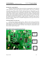
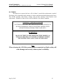
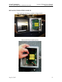
Acoustic Monitor User’s Manual
Axiom Technologies
15711W. Hardy Road, Suite 1, Houston, Texas 77060
Axiom Technologies L.L.C
15711 W. Hardy Road, Suite 1
Houston, Texas 77060
Phone 281 528 0201
Telephone: 281 931 0907
Fax: 281 231 6562
www.axiomsafety.com
ACOUSTIC MONITOR
USER’S MANUAL
TRANSMITTER OPERATION
July 26, 2012
1
Acoustic Monitor User’s Manual
Axiom Technologies
15711W. Hardy Road, Suite 1, Houston, Texas 77060
Phone 281 528 0201
Table of Contents
Introduction…………………………………………………………….3
Getting Started…………………...…………………………………….4
Choosing a Location…………………………………………………5-6
Delay Dip Switches…………………………………………..………...7
Interruption Dip Switches…………………………………..…….….7
Transmitter Configuration…………………………………...………8
Alarm Address ID……………………………………………..……...8
Operation……………………………………………………………...9
Sensitivity Adjustment……………………………………………....10
LED Bar Graph………………………………………………….......10
Last Alarm Pushbutton……………………………………………..11
SW1 Master Reset Button…………………………………………..11
Pairing With A Receiver…………………………………………....11
Maintenance……………………………………………………....…11
Batteries…………………………………………………….…12,13,14
Specifications………………………………………………….……..14
July 26, 2012
2
Acoustic Monitor User’s Manual
Axiom Technologies
15711W. Hardy Road, Suite 1, Houston, Texas 77060
Phone 281 528 0201
INTRODUCTION
The Axiom Technologies Wireless Acoustic Monitor (ATAM) was designed to provide a
reliable, cost-effective means of detecting the discharge of gases under pressure within its close
proximity. Typically, the monitor is installed near points prone to major leaks, such as choke
nipples, or above-ground bends in the flowline. Because of the compact aluminum enclosure and
wireless capability, this monitor can be easily moved to a different area during workover, or
construction. The transmitter is powered by a modular lithium battery pack which provides an
estimated two-year lifespan and is interchangeable with most Axiom Technologies safety
equipment.
Leak detection is accomplished using an external ultrasound microphone connected to a
microcontroller, which filters out unwanted transient noise. During persistent alarm conditions, a
wireless signal is sent to a receiver unit which can be connected to Axiom Technologies safety
equipment, a PLC, telemetry system, or any other devices capable of monitoring contact closure.
Additionally, the ATAM can be used to transmit two additional field alarms. This can be
used to connect (wired) end devices and transmit them wirelessly with an estimated range of up
to 1000’. Up to seven transmitters can be paired with a single receiver using an ID code that is
generated from over 30,000 possibilities, further enhancing the security of each transmission.
July 26, 2012
3
Acoustic Monitor User’s Manual
Axiom Technologies
15711W. Hardy Road, Suite 1, Houston, Texas 77060
Phone 281 528 0201
GETTING STARTED
Typically, the Axiom Technologies Acoustic Monitor (ATAM) transmitter is shipped
with the battery module installed in the “storage position” for shipment. Open the transmitter
box and remove the four nylon nuts holding the battery module, rotate it 180º and carefully reinstall as shown in (fig 1.) of this manual. The Axiom Technologies logo on the battery pack
should be turned to the right side. (For further instruction, see the BATTERY section of this
manual.) The transmitter is now energized and the green “O.K.” LED is blinking every second.
(fig 1.)
Fig. 1 ATAM General Layout with Battery
Nylon
Nuts
Lithium
Battery
Pack
Axiom
Technologies
Logo
Green “O.K.”
LED
Switch
Switch
Switch
Always avoid opening the enclosure in a dusty or rainy environment.
Batteries must only be changed or turned around in an area known to be
non-hazardous.
July 26, 2012
4
Acoustic Monitor User’s Manual
Axiom Technologies
15711W. Hardy Road, Suite 1, Houston, Texas 77060
Phone 281 528 0201
CHOOSING A LOCATION
Because of the compact nature of the ATAM and the unistrut on the back of the mounting
plate, it can be easily installed in likely problem areas. Be aware in mounting the device that
ultrasound travels very readily through metal. Therefore, the device should not be tightly
anchored to any pipes which will have high frequency vibrations due to normal processes. Either
attach the Acoustic Monitor to non-process structures, or provide ultrasound-deadening material
between the mounting plate and the pipe. Typical installation is within 10-15 feet of spots being
monitored. It is also important the ATAM be installed with an unobstructed view of the area
prone to leaks and the receiver, whenever possible. Periodically check to verify that the external
microphone is not blocked by accumulated foreign substances (mud, grease, snow, ice, etc.), as
this may adversely affect its performance.
Fig 2. Choke Nipple and Associated Piping
Choke
Nipple
Chokes and choke nipples can erode as a result of sand used in the fracturing process. The same
sand can also affect the elbows and crosses associated with flow line piping. Careful
consideration should be used when choosing a mounting place for the ATAM. The monitor’s
limited range is an attribute when heavy construction is occurring nearby, because most of the
transient ultrasonic frequencies will dissipate.
July 26, 2012
5
Acoustic Monitor User’s Manual
Axiom Technologies
15711W. Hardy Road, Suite 1, Houston, Texas 77060
Phone 281 528 0201
Fig 3. Wellhead, choke, and piping
For wellhead monitoring, one suggested method
of mounting the ATAM is on a
pipe that is independent of the process. The pipe
should be slightly taller than the choke height.
Include a union close to ground level so that the
pipe may be removed for workover or well
maintenance. Distance should be 10-15 feet away
from the piping with the external MIC pointing
directly at the problem area. Use the built-in
unistrut bracket on the back of the ATAM to
securely fasten it to the pipe via pipe clamps.
Choke
Nipple
.
July 26, 2012
6
Acoustic Monitor User’s Manual
Axiom Technologies
15711W. Hardy Road, Suite 1, Houston, Texas 77060
Phone 281 528 0201
DELAY DIP SWITCHES (fig 4.):
These adjust the amount of time that the alarm condition must remain in order to initiate a
shutdown transmission. They are selectable individually or collectively in 5, 10, 20, or 40 second
increments by switching to the ON position.
INTERRUPTION DIP SWITCHES (fig 4.)
An interruption is a short period of time when the ultrasound amplitude drops back below
the alarm threshold. It is common with water saturated gas to generate an erratic, inconsistent
ultrasound level during a pipe rupture. Due to this transient nature of ultrasound frequencies, it is
sometimes necessary to “ignore” fluctuations. For that reason, the ATAM has four dip switches
that allow the ultrasound level to fluctuate for a period of time without resetting the delay timer.
They are selectable individually or collectively in ½, 1, 2, or 4 second increments by switching to
the ON position.
Fig 4. Dip Switch Configuration (Battery Removed.)
Interruption
Dip
Switches
Delay Dip
Switches
ON
Interruption
Switches
Delay
Switches
July 26, 2012
OFF
4
2
1
1/2
40
20
10
5
. Note that a 4-1/2
second interruption
has been selected
Alarm
Address I.D.
Dip Switches
1-4
Note that a 40
second delay has
been selected.
7
Acoustic Monitor User’s Manual
Axiom Technologies
15711W. Hardy Road, Suite 1, Houston, Texas 77060
Phone 281 528 0201
TRANSMITTER ALARM ADDRESS I.D.CONFIGURATION
The transmitter board transmits data to the receiver board each time there is a change in
an alarm condition (and every 30 minutes as a service check). The alarm condition will be
indicated on the receiver board based on the ALARM Address ID (fig 4.) set on the transmitter
board using three Alarm Address I.D. Dip Switches. The Dip switch address is set by putting the
switch in the ON position. The code is based on a binary setting in which each of the three
switches are assigned a value of 1, 2, or 4. The total of all energized switch values is added to
determine which alarm channel will be used. For example:
Switch 1 On - Alarm channel 1
Switch 2 ON - Alarm channel 2
Switch 1 and 2 ON - Alarm channel 3
Switch 4 ON - Alarm channel 4
Switch 4 and 1 ON - Alarm channel 5
Switch 4 and 2 ON - Alarm channel 6 (See example below)
Switch 4, 2 and 1 ON - Alarm channel 7
All switches OFF – none used
Alarm Address ID Configuration
OFF ON
1
2
4
Test
Transmitter
set to alarm
channel #6
Test Mode (Activate LED Bar Graph)
OFF ON
1
2
4
Test
Transmitter
set to test
mode.
FIELD INPUTS/OUTPUTS
Each ATAM can be used to wirelessly transmit external alarm signals using the
Input/Output terminals located above the battery module. These consist of two open collector
type inputs (pull to ground), each with a zener diode for monitoring wiring integrity. The diode is
located in an “jumper”assembly containing a BLUE and a WHITE wire, which are shrinkwrapped on one end. Upon battery module installation, the ATAM processor will “search” for
these diodes and either activate these channels (if found), or ignore these channels (if not). The
typical field wiring would consist of a 2 wire, normally open circuit which uses a signal wire, a
ground wire, and a zener diode wired in parallel at the end device. Polarity reversal of the diode
will result in alarm. White should always be wired to ground and blue always to the input signal.
The ATAM also has one “pull to ground” normally open output which does not require a zener
diode.
July 26, 2012
8
Axiom Technologies
15711W. Hardy Road, Suite 1, Houston, Texas 77060
Acoustic Monitor User’s Manual
Phone 281 528 0201
OPERATION
Any alarm from the MIC or either of the Field Inputs will cause the Transmitter to send
alarm data. The Alarm will be resent every 5 minutes, as long as there is any alarm. Anytime
there is a change in the alarm state from On to Off the data will be sent.
Under normal conditions, the green “O.K.” LED (fig 5.) will continuously flash once
every second. When the ATAM detects a level of ultrasound above the threshold parameters, the
“DETECTED” LED (fig 5.) will alternately flash every two seconds. If a condition persists
beyond the delay setting, the “XMIT” (fig 5.) and “ALARM” LED (fig 5.) will repeatedly flash,
announcing that a wireless transmission has been sent to the receiver. The “ALARM” LED will
not stop flashing until the alarm condition goes away.
Fig 5. LED Placement
XMIT
LED
DETECTED
LED
ALARM
LED
OK
LED
July 26, 2012
9
Axiom Technologies
15711W. Hardy Road, Suite 1, Houston, Texas 77060
Acoustic Monitor User’s Manual
Phone 281 528 0201
SENSITIVITY ADJUSTMENT
Sensitivity adjustment should be done in the field on a situational basis. Each ATAM will
require adjustment to ensure proper operation in an alarm condition. While Axiom Technologies
can provide our customers with an ultrasonic signal generator for testing purposes, we also
recommend utilizing compressed air or inert gas for final verification. A sensitivity adjustment
switch (fig 6.) provides ten gain (amplification) adjustment settings. Turning this switch
clockwise with a small screwdriver will increase the gain in 10% increments. Final adjustments
should be done with the following consideration: Water saturation has a major effect on the
ultrasound level produced during a blowout. In situations where wells produce very “wet” gas,
the ATAM gain will need to be adjusted to a higher sensitivity. In situations where the unit is
deemed to sensitive, perhaps due to unavoidable background noise, the gain will need to be
decreased accordingly.
LED BAR GRAPH (Test mode only)
Switch position 4 (fig 6) is used for testing. With this switch is ON, press SW1 Reset
Button and release. The Bar Graph LEDS (fig 6.) on the board are now used to indicate the level
of the sound into the Microphone and the board does not transmit data. Testing with the LED
BAR GRAPH should be done with the ATAM door closed, using the viewing window on the
door to monitor registered frequencies.
Fig 6. ATAM General Layout (Battery Pack Removed)
Sensitivity
Adjustment
Switch
LED Bar
Graph (Test
Mode Only)
Alarm
Address
Switch
Position 4
.
July 26, 2012
10
Axiom Technologies
Acoustic Monitor User’s Manual
15711W. Hardy Road, Suite 1, Houston, Texas 77060
Phone 281 528 0201
LAST ALARM PUSHBUTTON (fig 7.)
Each time this is pressed the board transmits data to the receiver. You will press and hold
while you are having a receiver board learn the RF ID code. If you are learning an RF ID code
on a receiver board the switch setting for the Alarm ID does not matter as long as Alarm Address
switch position 4 is not ON.
SW1 MASTER RESET BUTTON (fig 7.)
This is a hardware reset of the board and restarts the program. It is also used to initiate
the LED Bar Graph mode..
Fig 7. ATAM Board (Battery Pack Removed.)
SW1
Master
Reset
Switch
Internal
Microphone
Last Alarm
Pushbutton
PAIRING YOUR ATAM WITH A RECEIVER
This is covered in the RECEIVER section of the user manual.
MAINTENANCE
The ATAM requires little maintenance but a minimum of a monthly visual examination
and testing is required to insure that the unit as well as the systems and devices associated with
the safety shutdown are operating properly. Periodic checks are required to verify that the
external microphone is not blocked by accumulated foreign substances (mud, grease, snow, ice,
etc.), as this may adversely affect its performance. Because of the changing nature of gas wells
and associated components, recalibration should be done on a well-to-well basis every 90 days
minimum.
July 26, 2012
11
Acoustic Monitor User’s Manual
Axiom Technologies
15711W. Hardy Road, Suite 1, Houston, Texas 77060
Phone 281 528 0201
BATTERIES
The batteries are expected to have a life of about 2 years before replacement is needed.
The battery life is dependent on the amount of wireless transmissions during that period of time.
The ATAM routinely reads battery voltages and provides warnings if the batteries need
replacement. Channel 8 on the receiver is used to indicate a low battery condition.
WARNING - EXPLOSION HAZARD
BATTERIES MUST ONLY BE CHANGED IN AN AREA KNOWN TO
BE NON-HAZARDOUS. REPLACE BATTERY MODULE WITH
AXIOM TECHNOLOGIES BATTERY PACK ONLY.
WARNING
DO NOT ATTEMPT TO RECHARGE BATTERY MODULE AS
THIS MAY TRIGGER AN UNSTABLE CONDITION WITHIN
THE LITHIUM CELLS AND CAUSE AN EXPLOSION
Note
When cleaning the ATAM do not use abrasives materials or fluids as they will
cause damage and severely reduce system’s reliability.
July 26, 2012
12
Acoustic Monitor User’s Manual
Axiom Technologies
15711W. Hardy Road, Suite 1, Houston, Texas 77060
Phone 281 528 0201
REPLACING THE BATTERY MODULE
Open enclosure; the battery module is shipped inside.
Unscrew the four (4) nylon spacers.
July 26, 2012
13
Acoustic Monitor User’s Manual
Axiom Technologies
15711W. Hardy Road, Suite 1, Houston, Texas 77060
Phone 281 528 0201
Align the battery module with threaded studs and push it in place gently.
The “Axiom Technologies” printing on the module is to be on the right.
Note:
Secure the battery module by reinstalling nylon spacers. Verify the green LED blinks
about once per second to confirm successful battery module installation.
ATAM - ENVIRONMENTAL SPECIFICATIONS
Temperature range
Humidity range
Altitude
Hazardous Area Classification
:
:
:
:
-40 to +85ºC
0 To 95% max., non condensing
2,000 m. max.
This product is pending certification.
ATAM - SENSOR RATINGS
Sensors Trip Setting : To be determined by customer during installation
ATAM - ELECTRICAL RATINGS
Electrical Source : Dual voltage lithium battery module3.6 & 14.4 VDC
Current consumption : 285 mA max. on 3.6VDC Circuits
435 mA on 14.4VDC Circuits
July 26, 2012
14