1
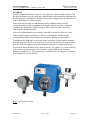
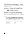
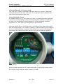
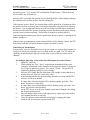
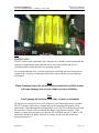
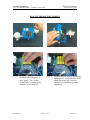
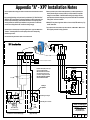
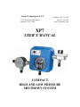
Axiom Technologies L.L.C
15731 W. Hardy Road, Suite 7
Houston, Texas 77060
Telephone: 281 931 0907
Fax: 281 231 6562
www.axiomsafety.com
XP7
USER’S MANUAL
COMPACT
HIGH AND LOW PRESSURE
SHUTDOWN SYSTEM
XP7 User’s Manual
Axiom Technologies
15711 W. Hardy Rd., Suite 1, Houston, Texas 77060
Phone 281 931 0907
GENERAL
The XP7 alarm and shutdown system is a self supported, compact shutdown device that
has been designed to provide a safe and reliable mean to detect abnormal conditions on a
production process and initiate a shutdown if any of the reading shows the operation is no
longer within the pre-set safety margins.
The system has been built to withstand the adverse conditions of the oil-field
environment and provides a straightforward interface with the operator. Abnormal
conditions are indicated by indicator lamps (LEDs), each associated with a label
indicating the condition detected.
Powered by lithium batteries, the system is expected to operate for about five years
without replacing batteries and there is little or no maintenance needed besides
recommended periodical functionality test and gentle cleaning of contact points.
In addition to the High and Low pressure alarms associated with the bourdon assembly
included in the box, the XP7 can connect up to four (4) loop monitored external alarms
plus two solid state outputs for indicating shutdown and service needed respectively.
The external alarms channels can be connected to any “dry contact” (or “open collector”)
type of sensor such as pressure or level switches, manual ESD station, telemetry
shutdown commands etc. Each remote loop is monitored for wire integrity for insuring
that wiring faults are also detected.
Fig. 1 XP7 General Layout
Manual Rev. 4
June 13, 2014
Page 2 of 9
XP7 User’s Manual
Axiom Technologies
15711 W. Hardy Rd., Suite 1, Houston, Texas 77060
Phone 281 931 0907
INSTALLATION
Typically, the XP7 is shipped with the battery module installed in the “storage position”
for shipment. Remove the four studs holding the battery module, rotate it 180º and
carefully re-install as shown on page 8 of this manual. The XP7 is now energized and the
green LED blinking every second.
The unit can be wall mounted directly on the process line. The box is provided with a
drain at the bottom to remove water condensation. Do not mount the XP7 sideways or
upside down as this may allow rainwater to ingress and accumulate in the enclosure.
NOTE: XP7 DEVICE IS TO BE MOUNTED UPRIGHT IN
THE VERTICAL POSITION ONLY.
XP7 / Pressure Sensing
Monitored pressure (i.e. flow-line pressure) is to be connected to the Sensing Port.
Sensed pressure is not to exceed 10% over full scale as this would cause damage in the
instrument and void warranty. If the flow is prone to pressure spikes, a pulsation
dampener is to be installed between the sensing port and sensed fluid. It is recommended
that an isolation valve is installed between the sensing port and process to allow for
maintenance and testing.
NOTES:
Do not exceed rated range. When connecting pressure bourdon assembly
(bottom of XP7), dope or use Teflon tape on connection threads.
Use wrench on shank to tighten or loosen bourdon connection. Do not twist
case when installing, this will cause damage and void warranty. Do not overtighten.
The typical connection the solenoid valve is as follows:
Port 1 (normally closed)
Port 2 (common)
Port 3 (normally open)
Supply Pneumatic Pressure (100 PSI Typ.)
Actuator
Exhaust
Fig. 2 Solenoid pneumatic/hydraulic typical connection
Manual Rev. 4
June 13, 2014
Page 3 of 9
XP7 User’s Manual
Axiom Technologies
15711 W. Hardy Rd., Suite 1, Houston, Texas 77060
Phone 281 931 0907
Adjusting High and Low Pressure Alarm
The “Low Limit” contact is controlled by the knob on the left, while the “High Limit”
contact is controlled by the knob on the right. To set the limit contact, simply turn the
knob to the desired position in the scale.
Connecting Remote Sensors
As indicated before, the XP7 can connect up to four (4) external alarm sensors and each
external loop is independently monitored for detecting alarm conditions. In addition to
the above, the unit monitors the wiring integrity for wiring interruption, insulation
degradation, etc. Each alarm loop is designed to be non-incendive.
Each input channel has an “End Of line Zener” (EOZ) that is to be connected in parallel
with the sensing element. For example, if channel 3 of the field alarms is to be connected
to a level switch installed on a water tank, then the EOZ is to be removed from the XP7
junction box and connected in parallel with the level switch as shown in Appendix A
Fig. 3 Field Connection Box for nonincendive field wiring (See Appendix “A” for field
wiring details)
When in normal operation, the XP7 sends a short pulse of current to the remote sensors
for verifying wiring conditions and the existence of alarms.
Manual Rev. 4
June 13, 2014
Page 4 of 9
XP7 User’s Manual
Axiom Technologies
15711 W. Hardy Rd., Suite 1, Houston, Texas 77060
Phone 281 931 0907
With the EOZ (end of line Zener), the input should have a voltage between 7 and 8VDC,
however, given the shortness of the pulse, this voltage can not be verified with a regular
voltmeter.
To overcome the above difficulty, the XP7 offers a mode where the inputs are energized
for a few seconds at a time by following the procedure below:
-
-
Open junction box and have voltmeter ready for reading voltage
Press and hold the “Test – Reset” switch down to “Test” for about three seconds
and then release.
The first remote alarm blinks the corresponding LED for five seconds while the
input is sending a current to the field connection.
Read the voltage on first remote channel and confirm it is between seven (7) and
eight (8) volts (around 7.3V being typical). A voltage below three (3) Volts is
considered as “alarm”.
- Voltages above 8 VDC indicate the remote sensor is not connected
- A reading of about 0 VDC may indicate the corresponding sensor is
“close”, or there is a short circuit in the loop or the XP7 timed out the test
on that channel.
- A low voltage of about 0.5VDC may indicate the EOZ (End Of line
Zener) has been connected backwards.
- Other low voltages (between 3 and 6 VDC) may indicate insulation’s
deterioration in the field wiring.
Once the XP7 stops the blinking the first channel and moves to channel 2, repeat
voltage reading.
OPERATION
The system can be commanded to “Reset” or “Test” by pressing the toggle switch up or
down respectively. By pushing to “Reset” the operator commands the unit to return to
the flowing condition. Pushing the “Test” function allows the operator to see the last
recorded cause of shutdown (corresponding LED blinks fast) and then the system
proceeds to slow blink each red LED to confirm all indicator circuits are operating
normally.
The system is shipped in the “RESET” condition. The needle of the gauge touching
either the “Low” or “High” set point causes the XP7 to switch the solenoid valve into
“shutdown”. The corresponding alarm LED will blink once a second to indicate the
actual cause of the shutdown even if the alarm goes away or another alarm is later
detected.
EXAMPLE. If an XP7 senses a “High Pressure” in a production line it will cause a
shutdown and the “High Pressure” LED will blink. After a number of hours, because of
the shutdown, the sensed pressure may fall to the point where the high pressure clears and
the needle of the gauge is now touching the low pressure alarm. In this case the XP7
continues flashing the “High Pressure” alarm LED until the operator presses “Reset”. If
the operator wants to confirm the cause of alarm after the system is back to normal, they
Manual Rev. 4
June 13, 2014
Page 5 of 9
XP7 User’s Manual
Axiom Technologies
15711 W. Hardy Rd., Suite 1, Houston, Texas 77060
Phone 281 931 0907
just need to press “Test” and the XP7 will blink the “High Pressure” LED to show the
last recorded cause of shutdown.
After the XP7 is installed, the operator is to set the high and low alarm settings and open
the isolation valve to allow pressure into the sensing port.
If the operator presses “Reset” the existing alarm will be ignored for 30 minutes to allow
the process to return to normal; there is no need to disturb the set-point before restoring
the process. It is recommended not to move the set points out of the alarm condition as
this involves the risk of the operator forgetting to return the alarms to the proper setting
once the process returns to normal. If more than 30 minutes is needed, then it is
suggested that the operator press “Reset” again before the time expires, re-starting the 30
minute countdown.
If the pressure (or temperature) returns to normal before 30 the minutes expires, the XP7
will re-arm itself and will initiate shutdown again if an alarm is sensed.
Time Delay on Alarm Inputs
In some cases, it may be desirable to have a slower response to a given alarm channel, i.e.
a tank level sensor may respond to waves or fluid motion in a tank. The XP7 offers the
capability of introducing an eight (8) seconds delay on any of the four remote alarm
channels.
For setting a time delay in any of the four field inputs, proceed as follows:
1Open XP7 enclosure
2While holding the “Test – Reset” switch down, momentarily depress the
“Initialize” pushbutton on the controller board (upper left corner as shown on
Fig 4, Page 6) and then let go the “Test – Reset” switch. The green LED
responds by flashing rapidly for a few seconds.
3Next, the XP7 flashes the first field alarm LED, rapidly to show that there is
no time delay set, slowly if a time delay exists.
4If the flashing indicates the desired setting, then take no action and the XP7
will move to the next channel.
5If a time delay is desired and the LED is flashing rapidly, press the “Test –
Reset” down to set a time delay.
6If a time delay is not wanted and the LED is flashing slowly, press the “Test –
Reset” up to remove the time delay.
7As the XP7 moves on to the next channel, repeat step 4 through 6 for setting
the desired operation mode.
8Once all channels have been set, the operator may repeat step 2 and confirm
each channel has been set correctly.
9Close the enclosure and confirm the actual delay by tripping the alarm
channels and observing the response on the XP7.
Manual Rev. 4
June 13, 2014
Page 6 of 9
XP7 User’s Manual
Axiom Technologies
15711 W. Hardy Rd., Suite 1, Houston, Texas 77060
Phone 281 931 0907
Fig 4 “Initialize” Pushbutton
MAINTENANCE
The XP7 requires little maintenance but a minimum of a monthly visual examination and
testing is recommended to insure that the unit as well as the systems and devices
associated with the safety shutdown are operating properly.
It is recommended that once a year the gauge pointer and High and Low limit points be
cleaned with a soft piece of cloth and a non residue contact cleaner to insure optimum
performance.
Note
When cleaning contacts do not use abrasives materials or fluids as they
will cause damage and severely reduce system’s reliability.
Note
Avoid opening the enclosure in a rainy or dusty environment.
The batteries are expected to have a life of about 5 years before replacement is needed.
The XP7 routinely reads battery voltages and provides warning if the batteries need
replacement. When the batteries are beginning to go low the XP7 will alternatively blink
the green and “Lo Batt” LEDs to indicate that battery replacement is needed. If the
batteries are not replaced within a few days the XP7 will blink only the “Lo Batt.” LED
and initiate shutdown as further reduction in voltage may prevent the system from
protecting the process.
Manual Rev. 4
June 13, 2014
Page 7 of 9
XP7 User’s Manual
Axiom Technologies
15711 W. Hardy Rd., Suite 1, Houston, Texas 77060
Phone 281 931 0907
WARNING - EXPLOSION HAZARD
BATTERIES MUST ONLY BE CHANGED IN AN AREA
KNOWN TO BE NON-HAZARDOUS. REPLACE BATTERY
MODULE WITH AXIOM TECHNOLOGIES PART
NUMBER AT-LBP-36144.
WARNING
DO NOT ATTEMPT TO RECHARGE BATTERY MODULE
AS THIS MAY TRIGGER AN UNSTABLE CONDITION
WITHIN THE LITHIUM CELLS AND CAUSE AN
EXPLOSION
Return used battery modules to Axiom Technologies for safe
disposal.
XP7 - ENVIRONMENTAL SPECIFICATIONS
Temperature range
Humidity range
Altitude
Hazardous Area Classification
:
:
:
:
-40 to +85ºC
0 To 95% max., non condensing
2,000 m. max.
Suitable for Class I, Division 2, Groups C & D,
Hazardous Locations. Temp. Code T3C
XP7 - PRESSURE RATINGS
Sensing Pressure : Ranges of up to 20,000 psi max
Solenoid Valve Pressure : 100 psi max. (standard), up to150 psi available
XP7 - ELECTRICAL RATINGS
Electrical Source : Dual voltage lithium battery module3.6 & 14.4 VDC
Current consumption : 285 mA max. on 3.6VDC Circuits
435 mA (3 A max. pulse) on 14.4VDC Circuits
Manual Rev. 4
June 13, 2014
Page 8 of 9
XP7 User’s Manual
Axiom Technologies
15711 W. Hardy Rd., Suite 1, Houston, Texas 77060
Phone 281 931 0907
PLACING THE BATTERY MODULE
Fig. 5
Remove screws from cover
Fig. 6
Open front cover
Fig. 7
Align the battery module with
threaded studs and push it in
place gently. The “Axiom
Technologies” printing on the
module is to be on the left.
Fig. 8
Secure battery module by reinstalling
nylon spacers. Verify the green LED
blinks about once per second to
confirm successful battery module
installation.
Manual Rev. 4
June 13, 2014
Page 9 of 9
Appendix "A" - XP7 Installation Notes
1- The XP7 operates with normally open contact and contact closure indicates that an alarm is
present.
2- For supervising field wiring, each input channel is provided with a 7.5V "End Of line Zener"
(EOZ) at the XP7's input terminals. At the time of installation, the EOZ is to be moved to the
end of the loop and connected in parallel with the alarm switch. If more than one switch
are daisy-chained, then the EOZ is to be installed at the very last switch. The EOZ at the
end of the alarm wiring allows the XP7 to confirm the wiring's integrity.
3- The EOZ must be connected in the correct polarity, Blue wire to "Signal" and White wire to
"Common". Connecting the EOZ on a reverse polarity will cause the corresponding
channel to stay on alarm.
5- Each input sends a pulse of 14VDC to the alarm switch. If the EOZ is connected (as it
should), then the voltage is cut down to 7.4VDC (+/- 0.3VDC) and the XP7 accepts this
voltage as a normal condition. If the EOZ would be missing or the wiring to the alarm
switch disconnected, then the voltage may rise up to about 14VDC which is considered a
"Wiring Failure" and cause a shutdown.
6- Multiple XP7s may share a single alarm switch such as a tank level, ESD station or any "dry
contact" alarm switch.
7- The output of an XP7 can be used as input for another XP7, or MI6 or MX16. Make sure the
EOZ is properly connected for wiring supervision.
4- The alarm switch may be located at 3,000FT or more from the XP7
XP7 Junction Box
SIGNAL INPUTS
1
2
3
4
SIGNAL COMMON
1
2
3
S.D. COM TRBL COM
4
Unused channel keeps EOZ connected to
End-Of-line Zener (EOZ) on each input
Typical of 4 supplied with XP7
EOZ must be removed and installed
with remote alarm switch as shown
on channels 1 through 5 of this sheet
MUST BE CONNECTED FOR WIRING
FAILURE ALARM TO GO AWAY!
Field Wiring
R1 - Malfunction
+ 12 or
24 VDC
source
-
Polarity IS
Important!
Red
Blue
R2 - Shutdown
blue
Blue Wire goes to "Signal"
Black
Control panel, external to the XP7 (Example Only)
white
White Wire goes to "Common"
White
Wire Nuts
EOZ (End Of line Zener)
To be connected as shown
(External Hi-Lo Pressure Switchgage)
High
Level
Switch
Axiom Technologies
XP7 Wiring Diagram
Monitored Inputs for
Safety Shutdown System
(High Tank Level)
Reference:
XP7
Sheet:
1 of 1
Rev:
1
Date:
2/28/2011