1
SFC and ST
Programming
Languages
Excerpts from :
- Logix5000 Controllers Common
Procedures, 1756-PM001H-EN-P
- Logix5000 Controllers General
Instructions Reference Manual,
1756-RM003H-EN-P
Programming Manual
Important User Information
Solid state equipment has operational characteristics differing from those of
electromechanical equipment. Safety Guidelines for the Application,
Installation and Maintenance of Solid State Controls (Publication SGI-1.1
available from your local Rockwell Automation sales office or online at
http://www.ab.com/manuals/gi) describes some important differences
between solid state equipment and hard-wired electromechanical devices.
Because of this difference, and also because of the wide variety of uses for
solid state equipment, all persons responsible for applying this equipment
must satisfy themselves that each intended application of this equipment is
acceptable.
In no event will Rockwell Automation, Inc. be responsible or liable for
indirect or consequential damages resulting from the use or application of
this equipment.
The examples and diagrams in this manual are included solely for illustrative
purposes. Because of the many variables and requirements associated with
any particular installation, Rockwell Automation, Inc. cannot assume
responsibility or liability for actual use based on the examples and diagrams.
No patent liability is assumed by Rockwell Automation, Inc. with respect to
use of information, circuits, equipment, or software described in this manual.
Reproduction of the contents of this manual, in whole or in part, without
written permission of Rockwell Automation, Inc. is prohibited.
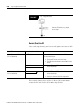
Throughout this manual we use notes to make you aware of safety
considerations.
WARNING
IMPORTANT
ATTENTION
Identifies information about practices or circumstances
that can cause an explosion in a hazardous environment,
which may lead to personal injury or death, property
damage, or economic loss.
Identifies information that is critical for successful
application and understanding of the product.
Identifies information about practices or circumstances
that can lead to personal injury or death, property
damage, or economic loss. Attentions help you:
• identify a hazard
• avoid a hazard
• recognize the consequence
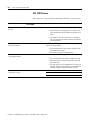
SHOCK HAZARD
Labels may be located on or inside the drive to alert
people that dangerous voltage may be present.
BURN HAZARD
Labels may be located on or inside the drive to alert
people that surfaces may be dangerous temperatures.
Preface
Purpose of this Manual
This manual contains excerpts from Logix5000 Controllers Common
Procedures, publication 1756-PM001H-EN-P and Logix5000 Controllers
General Instructions Reference Manual, publication
1756-RM003H-EN-P. This manual provides information on:
• Sequential Function Chart (SFC) programming language
• Structured Text (ST) programming language
• Jump to Subroutine (JSR), Subroutine (SBR), and Return (RET)
instructions needed to access SFC and ST logic
The term Logix5000 controller refers to any controller that is based on
the Logix5000 operating system, such as:
• CompactLogix™ controllers
• ControlLogix® controllers
• FlexLogix™ controllers
• PowerFlex® 700S with DriveLogix controllers
• SoftLogix5800™ controllers
Who Should Use this
Manual
This manual is intended for those individuals who program
applications that use Logix5000 controllers, such as:
• software engineers
• control engineers
• application engineers
• instrumentation technicians
When to Use this Manual
Use this manual when you perform these actions:
• develop the basic code for your application
• modify an existing application
• perform isolated tests of your application
As you integrate your application with the I/0 devices, controllers, and
networks in your system:
• Refer to the user manual for your specific type of controller.
• Use this manual as a reference, when needed.
1
Publication 1756-PM003H-EN-E - August 2005
Preface
2
How to Use this Manual
This manual is divided into the basic tasks that you perform while
programming a Logix5000 controller.
• Each chapter covers a task.
• The tasks are organized in the sequence that you will typically
perform them.
As you use this manual, you will see some terms that are formatted
differently from the rest of the text:
Text that is:
Identifies:
For example:
Italic
the actual name of an item that you Right-click User-Defined …
see on your screen or in an example
Right-click on the item that is named
User-Defined.
bold
an entry in the “Glossary”
If you want additional information, refer
to name in the “Glossary.”
Type a name …
Means:
If you are viewing the PDF file of the
manual, click name to jump to the
glossary entry.
courier
information that you must supply
based on your application (a
variable)
enclosed in brackets a keyboard key
Publication 1756-PM003H-EN-E - August 2005
Right-click
name_of_program …
You must identify the specific program in
your application. Typically, it is a name or
variable that you have defined.
Press [Enter].
Press the Enter key.
Table of Contents
Chapter 4
Design a Sequential Function
Chart
When to Use This Chapter. . . . . . . . . . . .
What is a Sequential Function Chart? . . . .
Define the Tasks . . . . . . . . . . . . . . . . . . .
Choose How to Execute the SFC . . . . . . .
Define the Steps of the Process . . . . . . . .
Organize the Steps . . . . . . . . . . . . . . . . .
Add Actions for Each Step . . . . . . . . . . . .
Describe Each Action in Pseudocode . . . .
Choose a Qualifier for an Action . . . . . . .
Define the Transition Conditions . . . . . . .
Transition After a Specified Time . . . . . . .
Turn Off a Device at the End of a Step . .
Keep Something On From Step-to-Step . .
End the SFC . . . . . . . . . . . . . . . . . . . . . .
Nest an SFC . . . . . . . . . . . . . . . . . . . . . .
Configure When to Return to the OS/JSR .
Pause or Reset an SFC . . . . . . . . . . . . . . .
Execution Diagrams . . . . . . . . . . . . . . . .
.
.
.
.
.
.
.
.
.
.
.
.
.
.
.
.
.
.
.
.
.
.
.
.
.
.
.
.
.
.
.
.
.
.
.
.
.
.
.
.
.
.
.
.
.
.
.
.
.
.
.
.
.
.
.
.
.
.
.
.
.
.
.
.
.
.
.
.
.
.
.
.
.
.
.
.
.
.
.
.
.
.
.
.
.
.
.
.
.
.
.
.
.
.
.
.
.
.
.
.
.
.
.
.
.
.
.
.
.
.
.
.
.
.
.
.
.
.
.
.
.
.
.
.
.
.
.
.
.
.
.
.
.
.
.
.
.
.
.
.
.
.
.
.
.
.
.
.
.
.
.
.
.
.
.
.
.
.
.
.
.
.
.
.
.
.
.
.
.
.
.
.
.
.
.
.
.
.
.
.
.
.
.
.
.
.
.
.
.
.
.
.
.
.
.
.
.
.
.
.
.
.
.
.
.
.
.
.
.
.
.
.
.
.
.
.
.
.
.
.
.
.
.
.
.
.
.
.
.
.
.
.
.
.
4-1
4-2
4-5
4-6
4-6
4-11
4-15
4-19
4-19
4-20
4-25
4-28
4-34
4-38
4-41
4-42
4-43
4-43
.
.
.
.
.
.
.
.
.
.
.
.
.
.
.
.
.
.
.
.
.
.
.
.
.
.
.
.
.
.
.
.
.
.
.
.
.
.
.
.
.
.
.
.
.
.
.
.
.
.
.
.
.
.
.
.
.
.
.
.
.
.
.
.
.
.
.
.
.
.
.
.
.
.
.
.
.
.
.
.
.
.
.
.
.
.
.
.
.
.
.
.
.
.
.
.
.
.
.
.
.
.
.
.
.
.
.
.
.
.
.
.
.
.
.
.
.
.
.
.
.
.
.
.
.
.
.
.
.
.
.
.
.
.
.
.
.
.
.
.
.
.
.
.
.
.
.
.
.
.
.
.
.
.
.
.
.
.
.
.
.
.
.
.
.
.
.
.
.
.
.
.
.
.
.
.
.
.
.
.
.
.
.
.
.
.
.
.
.
.
.
.
.
.
.
.
.
.
.
.
.
.
.
.
.
.
.
.
5-1
5-1
5-3
5-5
5-6
5-7
5-8
5-10
5-12
5-12
5-14
5-16
5-16
5-20
5-21
5-22
Chapter 5
Program a Sequential Function
Chart
1
When to Use This Chapter. . . . . . . . . .
Add an SFC Element . . . . . . . . . . . . . .
Create a Simultaneous Branch . . . . . . .
Create a Selection Branch . . . . . . . . . .
Set the Priorities of a Selection Branch .
Return to a Previous Step . . . . . . . . . .
Configure a Step . . . . . . . . . . . . . . . . .
Program a Transition . . . . . . . . . . . . . .
Add an Action. . . . . . . . . . . . . . . . . . .
Configure an Action . . . . . . . . . . . . . .
Program an Action . . . . . . . . . . . . . . .
Assign the Execution Order of Actions .
Document an SFC . . . . . . . . . . . . . . . .
Configure the Execution of the SFC . . .
Verify the Routine . . . . . . . . . . . . . . . .
Edit an SFC Online . . . . . . . . . . . . . . .
.
.
.
.
.
.
.
.
.
.
.
.
.
.
.
.
.
.
.
.
.
.
.
.
.
.
.
.
.
.
.
.
Publication 1756-PM003H-EN-E - August 2005
Table of Contents
2
Chapter 6
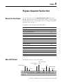
Program Structured Text
When to Use This Chapter.
Structured Text Syntax. . . .
Assignments . . . . . . . . . . .
Expressions . . . . . . . . . . .
Instructions. . . . . . . . . . . .
Constructs. . . . . . . . . . . . .
IF...THEN . . . . . . . . . . . . .
CASE...OF . . . . . . . . . . . . .
FOR…DO. . . . . . . . . . . . .
WHILE…DO. . . . . . . . . . .
REPEAT…UNTIL . . . . . . . .
Comments . . . . . . . . . . . .
.
.
.
.
.
.
.
.
.
.
.
.
.
.
.
.
.
.
.
.
.
.
.
.
.
.
.
.
.
.
.
.
.
.
.
.
.
.
.
.
.
.
.
.
.
.
.
.
.
.
.
.
.
.
.
.
.
.
.
.
.
.
.
.
.
.
.
.
.
.
.
.
.
.
.
.
.
.
.
.
.
.
.
.
.
.
.
.
.
.
.
.
.
.
.
.
.
.
.
.
.
.
.
.
.
.
.
.
.
.
.
.
.
.
.
.
.
.
.
.
.
.
.
.
.
.
.
.
.
.
.
.
.
.
.
.
.
.
.
.
.
.
.
.
.
.
.
.
.
.
.
.
.
.
.
.
.
.
.
.
.
.
.
.
.
.
.
.
.
.
.
.
.
.
.
.
.
.
.
.
.
.
.
.
.
.
.
.
.
.
.
.
.
.
.
.
.
.
.
.
.
.
.
.
.
.
.
.
.
.
.
.
.
.
.
.
.
.
.
.
.
.
.
.
.
.
.
.
.
.
.
.
.
.
.
.
.
.
.
.
.
.
.
.
.
.
.
.
.
.
.
.
.
.
.
.
.
.
.
.
.
.
.
.
.
.
.
.
.
.
.
.
.
.
.
.
.
.
.
.
.
.
.
.
.
.
.
.
6-1
6-1
6-2
6-4
6-11
6-12
6-13
6-16
6-19
6-22
6-25
6-28
When to Use This Chapter. . . . . . . . . . . . . . . .
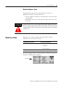
Precautions. . . . . . . . . . . . . . . . . . . . . . . . . . .
Check Force Status . . . . . . . . . . . . . . . . . . . . .
What to Force . . . . . . . . . . . . . . . . . . . . . . . . .
When to Use an I/O Force . . . . . . . . . . . . . . .
Add an I/O Force . . . . . . . . . . . . . . . . . . . . . .
When to Use Step Through . . . . . . . . . . . . . . .
Step Through a Transition or a Force of a Path.
When to Use an SFC Force . . . . . . . . . . . . . . .
Add an SFC Force . . . . . . . . . . . . . . . . . . . . . .
Remove or Disable Forces . . . . . . . . . . . . . . . .
.
.
.
.
.
.
.
.
.
.
.
.
.
.
.
.
.
.
.
.
.
.
.
.
.
.
.
.
.
.
.
.
.
.
.
.
.
.
.
.
.
.
.
.
.
.
.
.
.
.
.
.
.
.
.
.
.
.
.
.
.
.
.
.
.
.
.
.
.
.
.
.
.
.
.
.
.
.
.
.
.
.
.
.
.
.
.
.
. 13-1
. 13-2
. 13-3
. 13-5
. 13-5
. 13-6
. 13-7
. 13-7
. 13-7
. 13-9
13-10
Chapter 13
Force Logic Elements
Chapter 10
Program Control Instructions
(JSR, RET, SBR)
Publication 1756-PM003H-EN-E - August 2005
Introduction . . . . . . . . . . . . . . . . . . . . . . . . . . . . . . . . . . . 10-1
Jump to Subroutine (JSR), Subroutine (SBR), Return (RET) . 10-2
Chapter
4
Design a Sequential Function Chart
When to Use This Chapter
Use this chapter to design a sequential function chart (SFC) for
your process or system. An SFC is similar to a flowchart of your
process. It defines the steps or states through which your system
progresses. Use an SFC to:
• organize the functional specification for your system
• program and control your system as a series of steps and
transitions
By using an SFC to specify your process, you gain these advantages:
• Since an SFC is a graphical representation of your process, it is
easier to organize and read than a textual version. In addition,
RSLogix 5000 software lets you:
– add notes that clarify steps or capture important information
for use later on
– print the SFC to share the information with other individuals
• Since Logix5000 controllers support SFCs, you do not have to
enter the specification a second time. You are programming
your system as you specify it.
By using an SFC to program your process, you gain these advantages:
• graphical division of processes into its major logic pieces (steps)
• faster repeated execution of individual pieces of your logic
• simpler screen display
• reduced time to design and debug your program
• faster and easier troubleshooting
• direct access to the point in the logic where a machine faulted
• easy updates and enhancements
1
Publication 1756-PM003H-EN-E (excerpt from 1756-PM001H-EN-P) - August 2005
4-2
Design a Sequential Function Chart
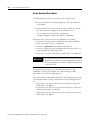
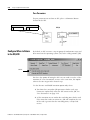
What is a Sequential
Function Chart?
A sequential function chart (SFC) is similar to a flowchart. It uses
steps and transitions to perform specific operations or actions. This
example shows the elements of an SFC:
Figure 4.1 SFC Example
A step represents a major function of your process. It contains the
actions that occur at a particular time, phase, or station.
An action is one of the functions that a step performs.
A transition is the true or false condition that tells the SFC
when to go to the next step.
A qualifier determines when an action starts and stops.
A simultaneous branch executes more than 1 step at
the same time.
Show or hide an
action.
JSR instruction calls a subroutine.
(continued on next page)
Publication 1756-PM003H-EN-E (excerpt from 1756-PM001H-EN-P) - August 2005
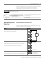
Design a Sequential Function Chart
4-3
Figure 4.2 SFC Example (continued from previous page)
A selection branch chooses between
different execution paths.
A text box lets you add descriptive text or notes to your SFC.
A stop lets you stop and wait for a command to restart.
A wire connects one element to another element anywhere on the chart. This wire takes you to the
conveyor step on Figure 4.1 on the previous page.
Publication 1756-PM003H-EN-E (excerpt from 1756-PM001H-EN-P) - August 2005
4-4
Design a Sequential Function Chart
To design a sequential function chart:
For this information:
See page:
Define the Tasks
4-5
Choose How to Execute the SFC
4-6
Define the Steps of the Process
4-6
Organize the Steps
4-11
Add Actions for Each Step
4-15
Describe Each Action in Pseudocode
4-19
Choose a Qualifier for an Action
4-19
Define the Transition Conditions
4-20
Transition After a Specified Time
4-25
Turn Off a Device at the End of a Step
4-28
Keep Something On From Step-to-Step
4-34
End the SFC
4-38
Nest an SFC
4-41
Configure When to Return to the OS/JSR
4-42
Pause or Reset an SFC
4-43
Execution Diagrams
4-43
Publication 1756-PM003H-EN-E (excerpt from 1756-PM001H-EN-P) - August 2005
Design a Sequential Function Chart
Define the Tasks
4-5
The first step in the development of an SFC is to separate the
configuration and regulation of devices from the commands to those
devices. Logix5000 controllers let you divide your project into one
continuous task and multiple periodic tasks and event tasks.
1. Organize your project:
These functions:
Go here:
configure and regulate devices
periodic task
command a device to a specific state
SFC in the continuous task
sequence the execution of your process
2. For those functions that go in a periodic task, group the
functions according to similar update rates. Create a periodic
task for each update rate.
For example, 2-state devices may require faster updates than
PID loops. Use separate periodic tasks for each.
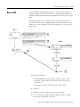
In this example, a project uses two periodic tasks to regulate motors,
valves, and temperature loops. An SFC to control the process.
EXAMPLE
Define the Tasks
This task (periodic) uses function block diagrams to turn on or
off motors and open or close valves. The SFC in MainTask
commands the state for each device. The function block
diagrams set and maintain that state.
This task (periodic) uses function block diagrams to configure
and regulate temperature loops. The SFC in MainTask
commands the temperatures. The function block diagrams set
and maintain those temperatures.
This task (continuous) executes the sequential function
chart (SFC). The SFC commands the specific state or
temperature for each device or temperature loop.
Publication 1756-PM003H-EN-E (excerpt from 1756-PM001H-EN-P) - August 2005
4-6
Design a Sequential Function Chart
Choose How to Execute the
SFC
To execute an SFC, either configure it as the main routine for a
program or call it as a subroutine.
If:
Then:
The SFC is the only routine in the program.
Configure the SFC as the main routine for the program.
The SFC calls all the other routines of the program.
The program requires other routines to execute
independent of the SFC.
1. Configure another routine as the main routine for
the program.
The SFC uses boolean actions.
2. Use the main routine to call the SFC as a
subroutine.
If the SFC uses boolean actions, then other logic must run
independent of the SFC and monitor status bits of the SFC.
Define the Steps of the
Process
A step represents a major function of your process. It contains the
actions that occur at a particular time, phase, or station.
Actions
Step
A step executes continuously until a
transition tells the SFC to go to the
next step.
Do this…
MIX
…and do this
Transition
• If true, go to the next step.
A transition ends a step. The transition defines the physical
conditions that must occur or change in order to go to the next step.
Publication 1756-PM003H-EN-E (excerpt from 1756-PM001H-EN-P) - August 2005
Design a Sequential Function Chart
4-7
Step Guidelines
As you define the steps of your process, follow these guidelines:
• Start with large steps and refine the steps in several passes.
first pass
Paint
second pass
third pass
Transfer_In
Transfer_In
Paint
Paint_Flow
Clean
Air_Flow
Elec_Charg
Clean
Transfr_Out
Transfr_Out
• When you first open an SFC routine, it contains an initial step
and transition. Use this step to initialize your process.
initial step
initial transition
The controller executes the initial step:
– after a project download when the controller goes into Run
mode.
– if the SFC is configured to, when the controller transitions to
Run mode and on power-up
– when the routine containing the chart is modified online and
the controller transitions to or from Test mode
• To identify a step, look for a physical change in your system,
such as new part that is in position, a temperature that is
reached, a preset time that is reached, or a recipe selection that
occurs. The step is the actions that take place before that
change.
Publication 1756-PM003H-EN-E (excerpt from 1756-PM001H-EN-P) - August 2005
4-8
Design a Sequential Function Chart
• Stop when your steps are in meaningful increments. For
example:
This organization of steps:
Is:
produce_solution
probably too large
set_mode, close_outlet, set_temperature,
open_inlet_a, close_inlet_a, set_timer,
reset_temperature, open_outlet, reset_mode
probably too small
preset_tank, add_ingredient_a, cook, drain
probably about right
SFC_STEP Structure
Each step uses a tag to provide information about the step. Access this
information via either the Step Properties dialog box or the Monitor
Tags tab of the Tags window:
If you want to:
determine how long a step has
been active (milliseconds)
flag when the step has been
active for a specific length of
time (milliseconds)
Then check or set Data type: Details:
this member:
T
DINT
When a step becomes active, the Timer (T) value resets and then
starts to count up in milliseconds. The timer continues to count up
until the step goes inactive, regardless of the Preset (PRE) value.
PRE
DINT
Enter the time in the Preset (PRE) member. When the Timer (T)
reaches the Preset value, the Done (DN) bit turns on and stays on
until the step becomes active again.
As an option, enter a numeric expression that calculates the time
at runtime.
flag if a step did not execute
long enough
DN
BOOL
When the Timer (T) reaches the Preset (PRE) value, the Done (DN)
bit turns on and stays on until the step becomes active again.
LimitLow
DINT
Enter the time in the LimitLow member (milliseconds).
• If the step goes inactive before the Timer (T) reaches the
LimitLow value, the AlarmLow bit turns on.
• The AlarmLow bit stays on until you reset it.
• To use this alarm function, turn on (check) the AlarmEnable
(AlarmEn) bit.
As an option, enter a numeric expression that calculates the time
at runtime.
AlarmEn
BOOL
To use the alarm bits, turn on (check) the AlarmEnable (AlarmEn)
bit.
AlarmLow
BOOL
If the step goes inactive before the Timer (T) reaches the LimitLow
value, the AlarmLow bit turns on.
• The bit stays on until you reset it.
• To use this alarm function, turn on (check) the AlarmEnable
(AlarmEn) bit.
Publication 1756-PM003H-EN-E (excerpt from 1756-PM001H-EN-P) - August 2005
Design a Sequential Function Chart
If you want to:
flag if a step is executing too
long
4-9
Then check or set Data type: Details:
this member:
LimitHigh
DINT
Enter the time in the LimitHigh member (milliseconds).
• If the Timer (T) reaches the LimitHigh value, the AlarmHigh
bit turns on.
• The AlarmHigh bit stays on until you reset it.
• To use this alarm function, turn on (check) the AlarmEnable
(AlarmEn) bit.
As an option, enter a numeric expression that calculates the time
at runtime.
AlarmEn
BOOL
To use the alarm bits, turn on (check) the AlarmEnable (AlarmEn)
bit.
AlarmHigh
BOOL
If the Timer (T) reaches the LimitHigh value, the AlarmHigh bit
turns on.
• The bit stays on until you reset it.
• To use this alarm function, turn on (check) the AlarmEnable
(AlarmEn) bit.
do something while the step is
active (including first and last
scan)
X
do something one time when the
step becomes active
FS(1)
BOOL
The X bit is on the entire time the step is active (executing).
Typically, we recommend that you use an action with a
N Non-Stored qualifier to accomplish this.
BOOL
The FS bit is on during the first scan of the step.
Typically, we recommend that you use an action with a P1 Pulse
(Rising Edge) qualifier to accomplish this.
do something while the step is
active, except on the first and
last scan
SA
BOOL
The SA bit is on when the step is active except during the first and
last scan of the step.
do something one time on the
last scan of the step
LS(1)
BOOL
The LS bit is on during the last scan of the step.
Use this bit only if you do the following: On the Controller
Properties dialog box, SFC Execution tab, set the Last Scan of
Active Step to Don’t Scan or Programmatic reset.
Typically, we recommend that you use an action with a P0 Pulse
(Falling Edge) qualifier to accomplish this.
determine the target of an SFC
Reset (SFR) instruction
Reset
BOOL
An SFC Reset (SFR) instruction resets the SFC to a step or stop
that the instruction specifies.
• The Reset bit indicates to which step or stop the SFC will
go to begin executing again.
• Once the SFC executes, the Reset bit clears.
determine the maximum time
that a step has been active
during any of its executions
determine if the Timer (T) value
rolls over to a negative value
TMax
DINT
Use this for diagnostic purposes. The controller clears this value
only when you select the Restart Position of Restart at initial step
and the controller changes modes or experiences a power cycle.
OV
BOOL
Use this for diagnostic purposes.
Publication 1756-PM003H-EN-E (excerpt from 1756-PM001H-EN-P) - August 2005
4-10
Design a Sequential Function Chart
If you want to:
Then check or set Data type: Details:
this member:
determine how many times a
step has become active
Count
DINT
This is not a count of scans of the step.
• The count increments each time the step becomes active.
• It increments again only after the step goes inactive and
then active again.
• The count resets only if you configure the SFC to restart at
the initial step. With that configuration, it resets when the
controller changes from program mode to run mode.
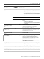
use one tag for the various
status bits of this step
(1)
Status
DINT
For this member:
Use this bit:
Reset
22
AlarmHigh
23
AlarmLow
24
AlarmEn
25
OV
26
DN
27
LS
28
SA
29
FS
30
X
31
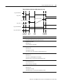
The FS and LS bits are only active during a step’s execution. Once a step finishes executing the code within its actions, the FS and/or LS bits are reset. If you reference
either of these bits in code outside of the SFC routine in a different part of the project, the bits are always cleared (0).
This diagram shows the relationship of the X, FS, SA, and LS bits.
step_name.X
step_name.FS
step_name.SA
step_name.LS
first scan
Publication 1756-PM003H-EN-E (excerpt from 1756-PM001H-EN-P) - August 2005
last scan
Design a Sequential Function Chart
Organize the Steps
4-11
Once you define the steps of your process, organize them into
sequences, simultaneous branches, selection branches, or loops.
To:
Use this structure:
With these considerations:
Execute 1 or more steps in sequence:
Sequence
The SFC checks the transition at the end of the
step:
• One executes repeatedly.
• If true, the SFC goes to the next step.
• Then the next executes repeatedly.
• Choose between alternative steps
or groups of steps depending on
logic conditions
• If false, the SFC repeats the step.
Selection Branch
• It is OK for a path to have no steps and
only a transition. This lets the SFC skip
the selection branch.
• By default, the SFC checks from left to
right the transitions that start each
path. It takes the first true path.
• Execute a step or steps or skip the
step or steps depending on logic
conditions
• If no transitions are true, the SFC
repeats the previous step.
• RSLogix 5000 software lets you change
the order in which the SFC checks the
transitions.
Execute 2 or more steps at the same time.
All paths must finish before continuing the
SFC
Simultaneous Branch
Loop back to a previous step
Wire to a Previous Step
• A single transition ends the branch.
• The SFC checks the ending transition
after the last step in each path has
executed at least once. If the transition
is false, the SFC repeats the previous
step.
• Connect the wire to the step or
simultaneous branch to which you want
to go.
• Do not wire into, out of, or between a
simultaneous branch.
Publication 1756-PM003H-EN-E (excerpt from 1756-PM001H-EN-P) - August 2005
4-12
Design a Sequential Function Chart
Here are some examples of SFC structures for different situations:
Example situation:
Example solution:
Station 45 and 46 of an assembly line work on parts
simultaneously. When both stations are done, the parts move
down 1 station.
Simultaneous Branch
Depending on the build code, a station either drills or polishes.
To simplify my programming, I want to separate communications
and block transfers from other control logic. All occur at the same
time.
45
46
Drill
Polish
Selection Branch
Simultaneous Branch
Control
In a heat treating area, the temperature ramps up at a specific
rate, maintains that temperature for a specific duration, and then
cools at a specific rate.
Comms
BTs
Sequence
Ramp
Maintain
Cool
At station 12, the machine drills, taps, and bolts a part. The steps
occur one after the other.
Sequence
Drill
Tap
Bolt
Step 12 inspects a process for the correct mix of chemicals.
Wire
• If OK, then continue with the remaining steps.
start of SFC
Step 12
• If not OK, go to the top of the SFC and purge the system.
Not OK
Publication 1756-PM003H-EN-E (excerpt from 1756-PM001H-EN-P) - August 2005
OK
Design a Sequential Function Chart
4-13
Sequence
A sequence is a group of steps that execute one after the other.
do this…
THEN this…
THEN this…
Selection Branch
A selection branch represents a choice between one path (step or
group of steps) or another path (i.e., an OR structure).
• Only one path executes.
• By default the SFC checks the transitions from left to right.
– The SFC takes the first true path.
– RSLogix 5000 software lets you change the order in which the
SFC checks the transitions (see chapter 5).
single horizontal
line
each path has its own
transition
do this…
OR this…
OR this…
This path skips the
structure (does
nothing).
single horizontal
line
Publication 1756-PM003H-EN-E (excerpt from 1756-PM001H-EN-P) - August 2005
4-14
Design a Sequential Function Chart
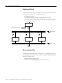
Simultaneous Branch
A simultaneous branch represents paths (steps or group of steps) that
occur at the same time (i.e., an AND structure).
• All paths execute.
• All paths must finish before continuing with the SFC.
• The SFC checks the transition after the last step of each path has
executed at least once.
one transition for all paths
do this…
AND this…
AND this…
double horizontal
line
double horizontal
line
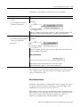
Wire to a Previous Step
In addition to connecting steps in sequences, simultaneous branches,
and selection branches, you can connect a step to a previous point in
your SFC. This lets you:
• loop back and repeat steps
• return to the beginning of the SFC and start over
Publication 1756-PM003H-EN-E (excerpt from 1756-PM001H-EN-P) - August 2005
Design a Sequential Function Chart
4-15
For example:
…go to this
step
If this condition
is true…
simple loop that repeats the
entire SFC
Add Actions for Each Step
path of a selection branch that returns to a
previous step
Use actions to divide a step into the different functions that the step
performs, such as commanding a motor, setting the state of a valve, or
placing a group of devices in a specific mode.
Step
Actions
Do this…
MIX
…and do this
How Do You Want to Use the Action?
There are two types of actions:
If you want to:
Then:
execute structured text directly in the SFC
Use a Non-Boolean Action
call a subroutine
use the automatic reset option to reset data upon leaving
a step
only set a bit and program other logic to monitor the bit to
determine when to execute.
Use a Boolean Action
Publication 1756-PM003H-EN-E (excerpt from 1756-PM001H-EN-P) - August 2005
4-16
Design a Sequential Function Chart
Use a Non-Boolean Action
A non-boolean action contains the logic for the action. It uses
structured text to execute assignments and instructions or call a
subroutine.
With non-boolean actions, you also have the option to postscan
(automatically reset) the assignments and instructions before leaving a
step:
• During postscan the controller executes the assignments and
instructions as if all conditions are false.
• The controller postscans both embedded structured text and any
subroutine that the action calls.
To automatically reset assignments and instructions, see “Turn Off a
Device at the End of a Step” on page 4-28.
Publication 1756-PM003H-EN-E (excerpt from 1756-PM001H-EN-P) - August 2005
Design a Sequential Function Chart
4-17
To program a non-boolean action, you have these options:
If you want to:
Then:
• execute your logic without additional Embed structured text.
routines
For example:
• use structured text assignments,
constructs, and instructions
When the S_Complete_the_Batch step is active, the S_Open_Outlet action executes. The
action sets the Outlet.ProgCommand tag equal to 1, which opens the outlet valve.
• re-use logic in multiple steps
Call a subroutine.
• use another language to program the For example:
action, such as ladder logic
• nest an SFC
When the S_Complete_the_Batch step is active, the S_Open_Outlet action executes. The
action calls the Open_Outlet routine.
Open_Outlet Routine
When the Open_Outlet routine executes, the OTE instruction sets the
Outlet.ProgCommand tag equal to 1, which opens the outlet valve.
You cannot reuse a non-boolean action within the same SFC except to
reset a stored action. Only one instance of a specific non-boolean
action is permitted per SFC.
Use a Boolean Action
A boolean action contains no logic for the action. It simply sets a bit in
its tag (SFC_ACTION structure). To do the action, other logic must
monitor the bit and execute when the bit is on.
With boolean actions, you have to manually reset the assignments and
instructions that are associated with the action. Since there is no link
between the action and the logic that performs the action, the
automatic reset option does not effect boolean actions.
Publication 1756-PM003H-EN-E (excerpt from 1756-PM001H-EN-P) - August 2005
4-18
Design a Sequential Function Chart
For example:
EXAMPLE
When the S_Complete_the_Batch step is active, the S_Open_Outlet action executes. When the action is active, its Q
bit turns on.
A ladder logic routine monitors the Q bit (S_Open_Outlet.Q). When the Q bit is on, the JSR instruction executes and
opens the outlet valve.
You can reuse a boolean action multiple times within the same SFC.
SFC_ACTION Structure
Each action (non-boolean and boolean) uses a tag to provide
information about the action. Access this information via either the
Action Properties dialog or the Monitor Tags tab of the Tags window:
If you want to:
determine when the action is
active
Then check or set
this member:
Q
Data type: Details:
BOOL
The status of the Q bit depends on whether the action is a boolean
action or non-boolean action:
If the action is:
Then the Q bit is:
boolean
on (1) the entire time the action is active,
including the last scan of the action
non-boolean
on (1) while the action is active but
off (0) at the last scan of the action
To use a bit to determine when an action is active, use the Q bit.
determine how long an action
has been active (milliseconds)
A
BOOL
The A bit is on the entire time the action is active.
T
DINT
When an action becomes active, the Timer (T) value resets and
then starts to count up in milliseconds. The timer continues to
count up until the action goes inactive, regardless of the Preset
(PRE) value.
Publication 1756-PM003H-EN-E (excerpt from 1756-PM001H-EN-P) - August 2005
Design a Sequential Function Chart
If you want to:
Then check or set
this member:
use one of these time-based
qualifiers: L, SL, D, DS, SD
PRE
4-19
Data type: Details:
DINT
Enter the time limit or delay in the Preset (PRE) member. The
action starts or stops when the Timer (T) reaches the Preset value.
As an option, enter a numeric expression that calculates the time
at runtime.
determine how many times an
action has become active
Count
DINT
This is not a count of scans of the action.
• The count increments each time the action becomes
active.
• It increments again only after the action goes inactive and
then active again.
• The count resets only if you configure the SFC to restart at
the initial step. With that configuration, it resets when the
controller changes from program mode to run mode.
use one tag for the various
status bits of this action
Describe Each Action in
Pseudocode
Status
DINT
For this member:
Use this bit:
Q
30
A
31
To organize the logic for an action, first describe the action in
pseudocode. If you are unfamiliar with pseudocode:
• Use a series of short statements that describe what should
happen.
• Use terms or symbols such as: if, then, otherwise, until, and, or,
=, >, <.
• Sequence the statements in the order that they should execute.
• If necessary, name the conditions to check first (when 1st) and
then the action to take second (what 2nd).
Enter the pseudocode into the body of the action. After you enter the
pseudocode, you can:
• Refine the pseudocode so it executes as structured text.
• Use the pseudocode to design your logic and leave the
pseudocode as comments. Since all structured text comments
download to the controller, your pseudocode is always available
as documentation for the action.
Publication 1756-PM003H-EN-E (excerpt from 1756-PM001H-EN-P) - August 2005
4-20
Design a Sequential Function Chart
To convert the pseudocode to structured text comments, add these
comment symbols:
For a comment:
Use one of these formats:
on a single line
//comment
that spans more than one line
(*start of comment . . . end of
comment*)
/*start of comment . . . end of
comment*/
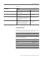
Choose a Qualifier for an
Action
Each action (non-boolean and boolean) uses a qualifier to determine
when it starts and stops.
The default qualifier is Non-Stored. The action starts when the step is
activated and stops when the step is deactivated.
To change when an action starts or stops, assign a different qualifier:
Table 4.1 Choose a Qualifier for an Action
If you want the action to:
And:
Then assign this Which
qualifier:
means:
start when the step is activated
stop when the step is deactivated
N
Non-Stored
execute only once
P1
Pulse (Rising
Edge)
stop before the step is deactivated or when the
step is deactivated
L
Time Limited
stay active until a Reset action turns off this action
S
Stored
stay active until a Reset action turns off this action
SL
Stored and
Time Limited
stop when the step is deactivated
D
Time Delayed
stay active until a Reset action turns off this action
DS
Delayed and
Stored
start a specific time after the step is activated, stay active until a Reset action turns off this action
even if the step is deactivated before this time
SD
Stored and
Time Delayed
or a specific time expires, even if the step is
deactivated
start a specific time after the step is activated
and the step is still active
Publication 1756-PM003H-EN-E (excerpt from 1756-PM001H-EN-P) - August 2005
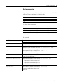
Design a Sequential Function Chart
4-21
Table 4.1 Choose a Qualifier for an Action
If you want the action to:
And:
Then assign this Which
qualifier:
means:
execute once when the step is activated
execute once when the step is deactivated
P
Pulse
start when the step is deactivated
execute only once
P0
Pulse (Falling
Edge)
R
Reset
turn off (reset) a stored action:
• S
Stored
• SL
Stored and Time Limited
• DS
Delayed and Stored
• SD
Stored and Time Delayed
Define the Transition
Conditions
The transition is the physical conditions that must occur or change in
order to go to the next step.
The transition tells the SFC when to go to the
next step.
transition
If true, go to the next step.
Publication 1756-PM003H-EN-E (excerpt from 1756-PM001H-EN-P) - August 2005
4-22
Design a Sequential Function Chart
Transitions occur in the:
For this structure:
Make sure that:
sequence
A transition is between each step.
steps
transitions
selection branch
Transitions are inside the horizontal lines.
transitions
simultaneous branch
Transitions are outside the horizontal lines.
transitions
Publication 1756-PM003H-EN-E (excerpt from 1756-PM001H-EN-P) - August 2005
Design a Sequential Function Chart
4-23
Here are two examples of transitions:
EXAMPLE
You want to:
a. Turn on 2 compressors. When a compressor is on,
the Device1State bit is on.
b. When both compressors are on, go to the next step.
Solution:
Init
Init_Done
compressor_1.Device1State = on (1)
and
EXAMPLE
You want to:
a. Package the product. When the product is in the
package, the package_done bit turns on.
b. Pack the product either 8 per carton or 16 per
carton.
Solution:
Package
carton_8
carton_16
Pack_8
package_done = on (1) and
carton_size = 8
Pack_16
package_done = on (1) and
carton_size = 16
To override the state of a transition, see “Force Logic Elements” on
page 13-1.
Publication 1756-PM003H-EN-E (excerpt from 1756-PM001H-EN-P) - August 2005
4-24
Design a Sequential Function Chart
Transition Tag
Each transition uses a BOOL tag to represent the true or false state of
the transition.
If the transition is:
The value is:
And:
true
1
The SFC goes to the next step.
false
0
The SFC continues to execute the
current step.
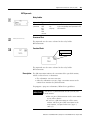
How Do You Want to Program the Transition?
To program the transition, you have these options:
If you want to:
Then:
enter the conditions as an expression in
structured text
Use a BOOL Expression
enter the conditions as instructions in
another routine
Call a Subroutine
use the same logic for multiple transitions
Use a BOOL Expression
The simplest way to program the transition is to enter the conditions
as a BOOL expression in structured text. A BOOL expression uses
bool tags, relational operators, and logical operators to compare
values or check if conditions are true or false. For example, tag1>65.
Here are some examples of BOOL expressions.
bool_tag_a
Publication 1756-PM003H-EN-E (excerpt from 1756-PM001H-EN-P) - August 2005
bool_tag_a &
bool_tag_b
dint_tag_a > 8
Design a Sequential Function Chart
4-25
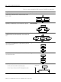
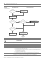
Call a Subroutine
To use a subroutine to control a transition, include an
End Of Transition (EOT) instruction in the subroutine. The EOT
instruction returns the state of the conditions to the transition, as
shown below.
2
3
1
- or -
JSR
2
If condition_1 & condition_2 &
condition_3 then
BOOL_tag := 1;
Else
BOOL_tag := 0;
End_if;
3
EOT(BOOL_tag);
1. Call a subroutine.
2. Check for the required conditions. When those conditions are
true, turn on a BOOL tag.
3. Use an EOT instruction to set the state of the transition equal to
the value of the BOOL tag. When the BOOL tag is on (true), the
transition is true.
Publication 1756-PM003H-EN-E (excerpt from 1756-PM001H-EN-P) - August 2005
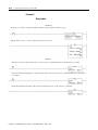
4-26
Design a Sequential Function Chart
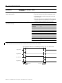
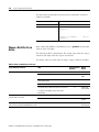
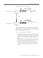
Transition After a Specified
Time
Each step of the SFC includes a millisecond timer that runs whenever
the step is active. Use the timer to:
• signal when the step has run for the required time and the SFC
should go to the next step
• signal when the step has run too long and the SFC should go to
an error step
Figure 4.3 Action of a timer and associated bits of a step:
step_name.X
step_name.PRE
step_name.T
step_name.DN
1
2
3
4
Description:
1. Step becomes active.
X bit turns on.
Timer (T) begins to increment.
2. Timer reaches the Preset (PRE) value of the step.
DN bit turns on.
Timer continues to increment.
3. Step becomes inactive.
X bit turns off.
Timer retains its value.
DN remains on.
4. Step becomes active.
X bit turns on.
Timer clears and then begins to increment.
DN bit turns off.
Publication 1756-PM003H-EN-E (excerpt from 1756-PM001H-EN-P) - August 2005
Design a Sequential Function Chart
4-27
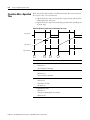
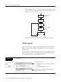
Figure 4.4 Action of the low and high alarms for a step:
step_name.AlarmEn
step_name.X
step_name.LimitHigh
step_name.LimitLow
step_name.T
step_name.AlarmHigh
step_name.AlarmLow
1
2
3
4
5
6
Description:
1. AlarmEn is on. To use the low and high alarms turn this bit on. Turn the bit on via
the properties dialog box or the tag for the step.
2. Step becomes active.
X bit turns on.
Timer (T) begins to increment.
3. Step becomes inactive.
X bit turns off.
Timer retains its value.
Since Timer is less than LimitLow, AlarmLow bit turns on.
4. Step becomes active.
X bit turns on.
Timer clears and then begins to increment.
AlarmLow stays on. (You have to manually turn it off.)
5. Timer reaches the LimitHigh value of the step.
AlarmHigh bit turns on.
Timer continues to increment.
6. Step becomes inactive.
X bit turns off.
Timer retains its value.
AlarmHigh stays on. (You have to manually turn it off.)
Publication 1756-PM003H-EN-E (excerpt from 1756-PM001H-EN-P) - August 2005
4-28
Design a Sequential Function Chart
Here is an example of the use of the Preset time of a step.
Functional specification says:
EXAMPLE
a. Cook the ingredients in the tank for 20 seconds.
b. Empty the tank.
Solution:
Cook
Cook.PRE = 20000 ms
Cook_Done
Cook.DN = on (1)
Empty_Tank
Here is an example of the use of the high alarm of a step.
EXAMPLE
Functional specification says:
a. Home 8 devices.
b. If all 8 devices are not home within 20 seconds, then shutdown the
system.
Solution:
Init
Init_OK
Init.LimitHigh = 20000 ms
Init_Not_OK
Step_1
Publication 1756-PM003H-EN-E (excerpt from 1756-PM001H-EN-P) - August 2005
Shutdown
Init.AlarmHigh
Design a Sequential Function Chart
Turn Off a Device at the End
of a Step
4-29
When the SFC leaves a step, you have several options on how to turn
off devices that the step turned on.
Programmatic Reset
Automatic Reset
use logic to clear
data
let the controller
automatically clear
data
Each option requires you to make these choices:
1. Choose a last scan option.
2. Based on the last scan option, develop your logic so that the last
scan returns data to the desired values.
Choose a Last Scan Option
On the last scan of each step, you have these options. The option that
you choose applies to all steps in all SFCs of this controller.
If you want to:
And on the last scan of a step:
Then:
See:
control which data to clear
Execute only P and P0 actions and use them to
clear the required data.
Use the Don’t Scan Option
page 4-30
Execute all actions and use either of these
options to clear the required data:
Use the Programmatic Reset Option
page 4-31
Use the Automatic Reset Option
page 4-33
• status bits of the step or action to
condition logic
• P and P0 actions
let the controller clear data
Publication 1756-PM003H-EN-E (excerpt from 1756-PM001H-EN-P) - August 2005
4-30
Design a Sequential Function Chart
This table compares the different options for handling the last scan of
a step:
Characteristic:
execution actions
During the last scan of a step, this option does:
Don’t scan
Programmatic reset
Only P and P0 actions execute.
They execute according to their
logic.
All actions execute according to
their logic.
Automatic reset
• P and P0 actions execute
according to their logic.
• All other actions execute
in postscan mode.
• On the next scan of the
routine, the P and P0
actions execute in
postscan mode.
retention of data values
All data keeps its current values.
All data keeps its current values.
• Data reverts to its values
for postscan.
• Tags to the left of [:=]
assignments clear to zero.
method for clearing data
reset of a nested SFC
Use P and P0 actions.
A nested SFCs remains at its
current step.
Use either:
Use either:
• status bits of the step or
action to condition logic
• [:=] assignment
(non-retentive assignment)
• P and P0 actions
• instructions that clear
their data during postscan
A nested SFCs remains at its
current step.
For the Restart Position property,
if you choose the Restart at initial
step option, then:
• A nested SFC resets to its
initial step.
• The X bit of a stop element
in a nested SFC clears to
zero.
Publication 1756-PM003H-EN-E (excerpt from 1756-PM001H-EN-P) - August 2005
Design a Sequential Function Chart
4-31
Use the Don’t Scan Option
The default option for handling the last scan of a step is Don’t scan.
With this option, all data keeps its current values when the SFC leaves
a step. This requires you to use additional assignments or instructions
to clear any data that you want to turn off at the end of a step.
To turn off a device at the end of a step:
1. Make sure that the Last Scan of Active Steps property is set to
the Don’t scan option (default).
2. Use a P0 Pulse (Falling Edge) action to clear the required data.
Make sure that the P0 action or actions are last in the order of
actions for the step.
During the last scan of the step, the Don’t scan option executes only
P and P0 actions. The assignments and instructions of the actions
execute according to their logic conditions.
• The controller does not execute a postscan of assignments or
instructions.
• When the SFC leaves the step, all data keeps its current values.
This example uses an action to turn on a conveyor at the start of a
step. A different action turns off the conveyor at the end of the step.
EXAMPLE
Use the Don’t Scan Option
This action turns on the conveyor. When conveyor_state turns
on, the conveyor turns on.
Before the SFC leaves the step, the P0 action turns off the
conveyor. On the last scan of the step, conveyor_state turns off.
This turns off the conveyor.
Publication 1756-PM003H-EN-E (excerpt from 1756-PM001H-EN-P) - August 2005
4-32
Design a Sequential Function Chart
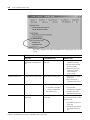
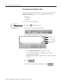
Use the Programmatic Reset Option
An optional method to programmatically turn off (clear) devices at the
end of a step is to execute all actions on the last scan of the step. This
lets you execute your normal logic as well as turn off (clear) devices
at the end of a step.
1. In the Last Scan of Active Steps property, select the
Programmatic reset option:
2. Clear the required data using any of these methods:
• To your normal logic, add logic that clears the required data.
Use the LS bit of the step or the Q bit of the action to
condition the execution of the logic.
• Use a P0 Pulse (Falling Edge) action to clear the required
data. Make sure that the P0 action or actions are last in the
order of actions for the step.
During the last scan of the step, the Programmatic reset option
executes all assignments and instructions according to logic
conditions.
• The controller does not postscan the assignments or
instructions.
• When the SFC leaves the step, all data keeps its current value.
This example uses a single action to turn on and off a conveyor. The
LS bit of the step conditions the execution of the logic. See “SFC_STEP
Structure” on page 4-8.
EXAMPLE
Use the Programmatic Reset Option and the LS Bit
When the step is not on its last scan (conveyor_fwd.LS = 0), this
statement turns on conveyor_state. When conveyor_state turns
on, the conveyor turns on.
On the last scan of the step (conveyor_fwd.LS =1), this
statement turns off conveyor_state. When conveyor_state turns
off, the conveyor turns off.
Publication 1756-PM003H-EN-E (excerpt from 1756-PM001H-EN-P) - August 2005
Design a Sequential Function Chart
4-33
For an action that uses one of the stored qualifiers, use the Q bit of
the action to condition your logic. See “SFC_ACTION Structure” on
page 4-18.
EXAMPLE
Use the Programmatic Reset Option and the Q Bit
When the action is not on its last scan (conveyor_start.Q =1),
this statement turns on conveyor_state. When conveyor_state
turns on, the conveyor turns on.
On the last scan of the action (conveyor_start.Q =0), this
statement turns off conveyor_state. When conveyor_state turns
off, the conveyor turns off.
You can also use a P0 Pulse (Falling Edge) action to clear data. This
example uses an action to turn on a conveyor at the start of a step. A
different action turns off the conveyor at the end of the step.
EXAMPLE
Use the Programmatic Reset Option and a P0 Action
This action turns on the conveyor. When conveyor_state turns
on, the conveyor turns on.
Before the SFC leaves the step, the P0 action turns off the
conveyor. On the last scan of the step, conveyor_state turns off.
This turns off the conveyor.
Publication 1756-PM003H-EN-E (excerpt from 1756-PM001H-EN-P) - August 2005
4-34
Design a Sequential Function Chart
Use the Automatic Reset Option
To automatically turn off (clear) devices at the end of a step:
1. In the Last Scan of Active Steps property, select the Automatic
reset option.
2. To turn off a device at the end of the step, control the state of
the device with an assignment or instruction such as:
• [:=] assignment (non-retentive assignment)
• Output Energize (OTE) instruction in a subroutine
During the last scan of each step, the Automatic reset option:
• executes P and P0 actions according to their logic conditions
• clears tags to the left of [:=] assignments
• executes a postscan of embedded structured text
• executes a postscan of any subroutine that an action calls via a
Jump to Subroutine (JSR) instruction
• resets any nested SFC (SFC that an action calls as a subroutine)
IMPORTANT
The postscan of an action actually occurs when the action
goes from active to inactive. Depending on the qualifier of
the action, the postscan could occur before or after the last
scan of the step.
As a general rule, the postscan executes instructions as if all
conditions are false. For example, the Output Energize (OTE)
instruction clears its data during postscan.
Some instructions do not follow the general rule during postscan. For
a description of how a specific instruction executes during postscan,
see:
• Logix5000 Controllers General Instructions Reference Manual,
publication 1756-RM003
• Logix5000 Controllers Process and Drives Instructions Reference
Manual, publication 1756-RM006
• Logix5000 Controllers Motion Instruction Set Reference Manual,
publication 1756-RM007
Publication 1756-PM003H-EN-E (excerpt from 1756-PM001H-EN-P) - August 2005
Design a Sequential Function Chart
4-35
Here is an example that uses a non-retentive assignment to control a
conveyor. It turns on a conveyor at the start of a step and
automatically turns off the conveyor when the step is done.
EXAMPLE
Automatically Clear Data
This action turns on the conveyor. When conveyor_state turns
on, the conveyor turns on.
When the SFC leaves the step, conveyor_state turns off. This
turns off the conveyor.
Keep Something On From
Step-to-Step
How Do You Want to Control the Device?
To provide bumpless control of a device during more than one time
or phase (step), do one of the following:
Option:
Example:
Use a Simultaneous Branch
Transfer_In
Make a separate step that controls the device.
Fan
Paint
Clean
Transfr_Out
Store and Reset an Action
Transfer_In
turn on the fan
Note the step that turns on the device and the step that turns off the device.
Paint
Later, define a Stored and Reset Action pair to control the device.
Clean
Transfr_Out
Use One Large Step
Paint
Use one large step that contains all the actions that occur while the device is on.
turn off the fan
transfer, paint, clean,
transfer, control the fan
Publication 1756-PM003H-EN-E (excerpt from 1756-PM001H-EN-P) - August 2005
4-36
Design a Sequential Function Chart
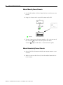
Use a Simultaneous Branch
A simple way to control a device or devices during one or more steps
is to create a separate step for the devices. Then use a simultaneous
branch to execute the step during the rest of the process.
EXAMPLE
A paint operation:
1. Transfers the product into the paint shop.
2. Paints the product using 3 separate paint guns.
3. Cleans the guns.
4. Transfers the product to the paint ovens.
During the entire process, the system must control the shop fans.
Solution:
Transfer_In
Paint_Flow
Air_Flow
Elec_Charg
Fan
Clean
Transfr_Out
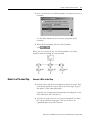
Store and Reset an Action
Typically, an action turns off (stops executing) when the SFC goes to
the next step. To keep a device on from step to step without a bump,
store the action that controls the device:
1. In the step that turns on the device, assign a stored qualifier to
the action that controls the device. For a list of stored qualifiers,
see Table 4.1 on page 4-20.
2. In the step that turns off the device, use a Reset action.
Publication 1756-PM003H-EN-E (excerpt from 1756-PM001H-EN-P) - August 2005
Design a Sequential Function Chart
4-37
This figure shows the use of a stored action.
S
Action_Name
action that you want to
execute for more than
one step
step that starts the action
more steps
R
step that stops the action
Action_Name
same name as the stored
action
When the SFC leaves the step that stores the action, RSLogix 5000
software continues to show the stored action as active. (By default, a
green border displays around the action.) This lets you know that the
SFC is executing the logic of that action.
To use a stored action, follow these guidelines:
• The Reset action only turns off the stored action. It does not
automatically turn off the devices of the action. To turn off the
device, follow the Reset action with another action that turns off
the device. Or use the Automatic reset option described on
page 4-33.
• Before the SFC reaches a stop element, reset any stored actions
that you do not want to execute at the stop. An active stored
action remains active even if the SFC reaches a stop.
• Use caution when you jump in between a step that stores an
action and a step that resets the action. Once you reset an
action, it only starts when you execute the step that stores the
action.
Publication 1756-PM003H-EN-E (excerpt from 1756-PM001H-EN-P) - August 2005
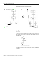
4-38
Design a Sequential Function Chart
In this example, steps 1 - 4 require a fan to be on. At the end of
step_4, the fan is reset (turned off). When the SFC jumps back to
step_3, the fan remains off.
step_1
turn on the fan
(stored)
step_2
step_3
step_4
turn off the fan
(reset)
To turn the fan back on, the SFC has to jump back to step_1.
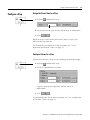
Use One Large Step
If you use one large step for multiple functions, then use additional
logic to sequence the functions. One option is to nest an SFC within
the large step.
In this example, a step turns on a fan and then calls another SFC. The
nested SFC sequences the remaining functions of the step. The fan
stays on throughout the steps of the nested SFC.
EXAMPLE
Use a Large Step
This action turns on a fan:
• fan.ProgProgReq lets the SFC command the state
of the fan.
• fan.ProgCommand turns on the fan.
This action calls another SFC. The SFC sequences the
remaining functions of the step.
Publication 1756-PM003H-EN-E (excerpt from 1756-PM001H-EN-P) - August 2005
Design a Sequential Function Chart
4-39
For additional information on how to nest an SFC, see “Nest an SFC”
on page 4-41.
End the SFC
Once an SFC completes its last step, it does not automatically restart at
the first step. You must tell the SFC what to do when it finishes the last
step.
To:
Do this:
automatically loop back to an
earlier step
Wire the last transition to the top of the step to which you want to go.
See “Wire to a Previous Step“on page 4-14.
stop and wait for a command to Use a Stop Element.
restart
See “Use a Stop Element” on page 4-38.
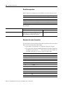
Use a Stop Element
The stop element lets you stop the execution of an entire SFC or a
path of a simultaneous branch and wait to restart. When an SFC
reaches a stop element:
• The X bit of the stop element turns on. This signals that the SFC
is at the stop element.
• Stored actions remain active.
• Execution stops for part or all of the SFC:
If the stop element is at the end of a:
Then:
sequence
entire SFC stops
selection branch
path within a simultaneous branch
only that path stops while the rest of the
SFC continues to execute.
Publication 1756-PM003H-EN-E (excerpt from 1756-PM001H-EN-P) - August 2005
4-40
Design a Sequential Function Chart
EXAMPLE
Use a Stop Element
When the SFC reaches last_step and
process_done is true, the execution of
the SFC stops.
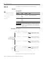
Restart (Reset) the SFC
Once at the stop element, you have several options to restart the SFC:
If the SFC is:
And the Last Scan of Active
Steps option is:
Then:
nested (i.e., another SFC calls this
SFC as a subroutine)
Automatic reset
At the end of the step that calls the nested SFC, the nested
SFC automatically resets:
• The nested SFC resets to the initial step.
• The X bit of the stop element in the nested SFC clears
to zero.
Programmatic reset
Don’t scan
1. Use an SFC Reset (SFR) instruction to restart the SFC
at the required step.
2. Use logic to clear the X bit of the stop element.
NOT nested (i.e., no SFC calls this
SFC as a subroutine)
1. Use an SFC Reset (SFR) instruction to restart the SFC
at the required step.
2. Use logic to clear the X bit of the stop element.
This example shows the use of the SFC Reset (SFR) instruction to
restart the SFC and clear the X bit of the stop element.
Publication 1756-PM003H-EN-E (excerpt from 1756-PM001H-EN-P) - August 2005
Design a Sequential Function Chart
EXAMPLE
4-41
Restart (Reset) the SFC
If SFC_a_stop.X = on (SFC_a is at the stop) and SFC_a_reset = on (time to reset the SFC) then
for one scan (ons[0] = on):
Reset SFC_a to SFC_a_Step_1
SFC_a_stop.X = 0
Publication 1756-PM003H-EN-E (excerpt from 1756-PM001H-EN-P) - August 2005
4-42
Design a Sequential Function Chart
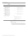
SFC_STOP Structure
Each stop uses a tag to provide information about the stop element:
If you want to:
determine when the SFC is at
the stop
Then check or set
this member:
X
Data type: Details:
• When the SFC reaches the stop, the X bit turns on.
BOOL
• The X bit clears if you configure the SFCs to restart at the
initial step and the controller changes from program to run
mode.
• In a nested SFC, the X bit also clears if you configure the
SFCs for automatic reset and the SFC leaves the step that
calls the nested SFC.
determine the target of an SFC
Reset (SFR) instruction
Reset
BOOL
An SFC Reset (SFR) instruction resets the SFC to a step or stop
that the instruction specifies.
• The Reset bit indicates to which step or stop the SFC will
go to begin executing again.
• Once the SFC executes, the Reset bit clears.
determine how many times a
stop has become active
Count
DINT
This is not a count of scans of the stop.
• The count increments each time the stop becomes active.
• It increments again only after the stop goes inactive and
then active again.
• The count resets only if you configure the SFC to restart at
the initial step. With that configuration, it resets when the
controller changes from program mode to run mode.
use one tag for the various
status bits of this stop
Status
DINT
For this member:
Use this bit:
Reset
22
X
31
Publication 1756-PM003H-EN-E (excerpt from 1756-PM001H-EN-P) - August 2005
Design a Sequential Function Chart
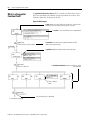
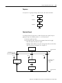
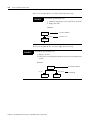
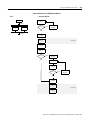
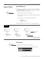
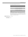
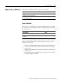
Nest an SFC
4-43
One method for organizing your project is to create one SFC that
provides a high-level view of your process. Each step of that SFC calls
another SFC that performs the detailed procedures of the step (nested
SFC).
This figure shows one way to nest an SFC. In this method, the last
scan option of the SFC is configured for either Programmatic reset or
Don’t scan. If you configure the SFC for Automatic reset, then step 1 is
unnecessary.
SFC_a
1
2
SFC_b
4
3
1. Reset the nested SFC:
• The SFR instruction restarts SFC_b at SFC_b_Step_1. Each
time SFC_a leaves this step and then returns, you have to
reset SFC_b.
• The action also clears the X bit of the stop element.
2. Call SFC_b.
3. Stop SFC_b. This sets the X bit of the stop element.
4. Use the X bit of the stop element to signal that SFC_b is done
and it is time to go to the next step.
Publication 1756-PM003H-EN-E (excerpt from 1756-PM001H-EN-P) - August 2005
4-44
Design a Sequential Function Chart
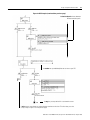
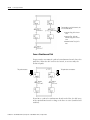
Pass Parameters
To pass parameters to or from an SFC, place a Subroutine/Return
element in the SFC.
Input Parameters
Return Parameters
❇
❇
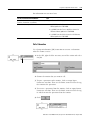
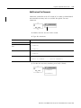
Configure When to Return
to the OS/JSR
SFC_b
By default, an SFC executes a step or group of simultaneous steps and
then returns to the operating system (OS) or the calling routine (JSR).
default
You have the option of letting the SFC execute until it reaches a false
transition. If several transitions are true at the same time, this option
reduces the time to get to the desired step.
Use the Execute until FALSE transition option only when:
1. You don’t have to update JSR parameters before each step.
Parameters update only when the SFC returns to the JSR. See
“Pass Parameters” on page 4-42.
2. A false transition occurs within the watchdog timer for the task.
If the time that it takes to return to a JSR and complete the rest
of the task is greater than the watchdog timer, a major fault
occurs.
Publication 1756-PM003H-EN-E (excerpt from 1756-PM001H-EN-P) - August 2005
Design a Sequential Function Chart
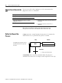
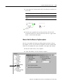
Pause or Reset an SFC
4-45
Two optional instructions are available that give you further control
over the execution of your SFC:
If you want to:
Then use this instruction:
pause an SFC
Pause SFC (SFP)
reset an SFC to a specific step or stop
Reset SFC (SFR)
Both instructions are available in the ladder logic and structured text
programming languages.
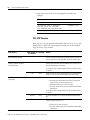
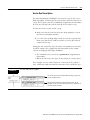
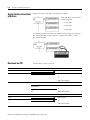
Execution Diagrams
The following diagrams show the execution of an SFC with different
organizations of steps or different selections of execution options.
For a diagram of the:
See page:
Execution of a Sequence
4-44
Execution of a Simultaneous Branch
4-45
Execution of a Selection Branch
4-46
When parameters enter and exit an SFC
4-46
Options for Execution Control
4-47
Publication 1756-PM003H-EN-E (excerpt from 1756-PM001H-EN-P) - August 2005
4-46
Design a Sequential Function Chart
Figure 4.5 Execution of a Sequence
This…
…executes like this
step_1
step_1
tran_1
step_2
tran_1
false
return to
OS/JSR
tran_2
true
return to
OS/JSR
last scan
step_1
step_2
tran_2
false
return to
OS/JSR
true
return to
OS/JSR
step_2
Publication 1756-PM003H-EN-E (excerpt from 1756-PM001H-EN-P) - August 2005
last scan
Design a Sequential Function Chart
4-47
Figure 4.6 Execution of a Simultaneous Branch
This…
…executes like this
step_1
step_1
tran_1
false
tran_1
step_2
step_3
return to
OS/JSR
true
tran_2
return to
OS/JSR
last scan
step_1
step_2
step_3
tran_2
true
false
return to
OS/JSR
step_2
step_3
tran_2
false
return to
OS/JSR
true
return to
OS/JSR
step_2
last scan
step_3
Publication 1756-PM003H-EN-E (excerpt from 1756-PM001H-EN-P) - August 2005
4-48
Design a Sequential Function Chart
Figure 4.7 Execution of a Selection Branch
This…
…executes like this
step_1
step_1
tran_2
tran_1
step_2
tran_3
tran_1
step_3
tran_4
false
true
tran_2
return to
OS/JSR
false
return to
OS/JSR
true
return to
OS/JSR
step_1
step_1
step_2
step_3
tran_3
false
return to
OS/JSR
tran_4
true
true
return to
OS/JSR
return to
OS/JSR
step_2
step_3
Figure 4.8 When parameters enter and exit an SFC
input parameters
step_1
input parameters
return parameters
return to
OS/JSR
false
tran_1
true
return parameters
input parameters
Publication 1756-PM003H-EN-E (excerpt from 1756-PM001H-EN-P) - August 2005
return to
OS/JSR
step_1
last scan
last scan
false
return to
OS/JSR
last scan
Design a Sequential Function Chart
4-49
Figure 4.9 Options for Execution Control
This…
step_1
tran_1
step_2
tran_2
…executes like this
Execute current active steps only
step_1
tran_1
Execute until FALSE transition
step_1
false
return to
OS/JSR
true
tran_1
false
return to
OS/JSR
true
return to
step_1
step_1
step_2
step_2
tran_2
true
false
return to
OS/JSR
tran_2
last scan
false
return to
OS/JSR
true
return to
OS/JSR
step_2
step_2
last scan
Publication 1756-PM003H-EN-E (excerpt from 1756-PM001H-EN-P) - August 2005
4-50
Design a Sequential Function Chart
Notes:
Publication 1756-PM003H-EN-E (excerpt from 1756-PM001H-EN-P) - August 2005
Chapter
5
Program a Sequential Function Chart
When to Use This Chapter
Use this chapter to enter a sequential function chart (SFC) into
RSLogix 5000 software. Enter the SFC as you design it. Or first design
the SFC and then enter it. To design the SFC, see “Design a Sequential
Function Chart” on page 4-1.
To program a sequential function chart routine:
Add an SFC Element
For this information:
See page:
Add an SFC Element
5-1
Create a Simultaneous Branch
5-3
Create a Selection Branch
5-5
Set the Priorities of a Selection Branch
5-6
Return to a Previous Step
5-7
Configure a Step
5-8
Program a Transition
5-10
Add an Action
5-12
Configure an Action
5-12
Program an Action
5-14
Assign the Execution Order of Actions
5-16
Document an SFC
5-16
Configure the Execution of the SFC
5-20
Verify the Routine
5-21
To add SFC elements, use the SFC toolbar.
start of selection
branch
step and transition
start of simultaneous
branch
stop
subroutine/return
step
transition
1
new path
text box
Publication 1756-PM003H-EN-E (excerpt from 1756-PM001H-EN-P) - August 2005
5-2
Program a Sequential Function Chart
Add and Manually Connect Elements
1. On the SFC toolbar, click the button for the item that you want
to add.
2. Drag the element to the required location on the SFC.
B
A
green dot
3. To wire (connect) two elements together, click a pin on one of
the elements A and then click the pin on the other
element B . A green dot shows a valid connection point.
Add and Automatically Connect Elements
1. Select (click) the element to which you want to connect a new
element.
2. With the element still selected, click the toolbar button for the
next element.
Publication 1756-PM003H-EN-E (excerpt from 1756-PM001H-EN-P) - August 2005
Program a Sequential Function Chart
5-3
Drag and Drop Elements
From the SFC toolbar, drag the button for the required element to the
desired connection point on the SFC. A green dot shows a valid
connection point.
green dot
Create a Simultaneous
Branch
Start a Simultaneous Branch
1. On the SFC toolbar, click the
to the desired location.
button. Drag the new branch
Publication 1756-PM003H-EN-E (excerpt from 1756-PM001H-EN-P) - August 2005
5-4
Program a Sequential Function Chart
2. To add a path to the branch, select (click) the first step of the
path that is to the left of where you want to add the new path.
Click
A
B
green dot
3. To wire the simultaneous branch to the preceding transition,
click the bottom pin of the transition A and then click the
horizontal line of the branch B . A green dot shows a valid
connection point.
End a Simultaneous Branch
1. Select the last step of each path in the branch. To select the
steps, you can either:
• Click and drag the pointer around the steps that you want to
select.
• Click the first step. Then press and hold [Shift] and click the
rest of the steps that you want to select.
2. On the SFC toolbar, click
Publication 1756-PM003H-EN-E (excerpt from 1756-PM001H-EN-P) - August 2005
Program a Sequential Function Chart
5-5
3. Add the transition that follows the simultaneous branch.
B
A
green dot
4. To wire the simultaneous branch to the transition, click the top
pin of the transition A and then click the horizontal line of the
branch B . A green dot shows a valid connection point.
Create a Selection Branch
Start a Selection Branch
1. On the SFC toolbar, click the
branch to the desired location.
button. Then drag the new
2. To add a path to the branch, select (click) the first transition of
the path that is to the left of where you want to add the new
path. Click
A
B
green dot
3. To wire the selection branch to the preceding step, click the
bottom pin of the step A and then click the horizontal line of
the branch B . A green dot shows a valid connection point.
Publication 1756-PM003H-EN-E (excerpt from 1756-PM001H-EN-P) - August 2005
5-6
Program a Sequential Function Chart
End a Selection Branch
1. Select the last transition of each path in the branch. To select the
transitions, you can either:
• Click and drag the pointer around the transitions that you
want to select.
• Click the first transition. Then press and hold [Shift] and click
the rest of the transitions that you want to select.
2. On the SFC toolbar, click
3. Add the step that follows the selection branch.
B
A
green dot
4. To wire the selection branch to the step, click the top pin of the
step A and then click the horizontal line of the branch B . A
green dot shows a valid connection point.
Set the Priorities of a
Selection Branch
By default, the SFC checks the transitions that start a selection branch
from left to right. If you want to check a different transition first,
assign a priority to each path of the selection branch. For example, it
is a good practice to check for error conditions first. Then check for
normal conditions.
To assign priorities to a selection branch:
1. Right click the horizontal line that starts the branch and select
Set Sequence Priorities.
Publication 1756-PM003H-EN-E (excerpt from 1756-PM001H-EN-P) - August 2005
Program a Sequential Function Chart
5-7
2. Clear (uncheck) the Use default priorities check box and select a
transition.
Use the Move buttons to raise or lower the priority of the
transition.
3. When all the transitions have the desired priority,
click
When you clear (uncheck) the Use default priorities check box,
numbers show the priority of each transition.
Return to a Previous Step
Connect a Wire to the Step
1. Click the lower pin of the transition that signals the jump. Then
click the top pin of the step to which you want to go. A green
dot shows a valid connection point.
Typically, the resulting connection orients itself along the center
of the flowchart and is hard to see.
2. To make the jump easier to read, drag its horizontal bar above
the step to which the jump goes. You may also have to
reposition some of the SFC elements.
Publication 1756-PM003H-EN-E (excerpt from 1756-PM001H-EN-P) - August 2005
5-8
Program a Sequential Function Chart
For example, to go to Step_001 from Tran_003:
Drag the horizontal bar here.
1.
2.
Then click here.
Click here.
green dot
Hide a Wire
If a wire gets in the way of other parts of your SFC, hide the wire to
make the SFC easier to read. To hide a wire, right-click the wire and
select Hide Wire.
location to which the wire goes
To see the SFC element to which the wire goes, click the grid location
on the wire.
Publication 1756-PM003H-EN-E (excerpt from 1756-PM001H-EN-P) - August 2005
Program a Sequential Function Chart
Configure a Step
5-9
Assign the Preset Time for a Step
1. Click the
button of the step.
2. On the General tab, type the time for the step, in milliseconds.
3. Click
When the step is active for the preset time (Timer = Preset), the
DN bit of the step turns on.
To calculate the preset time for a step at runtime, see “Use an
Expression to Calculate a Time” on page 5-9.
Configure Alarms for a Step
To turn on an alarm if a step executes too long or not long enough:
1. Click the
button of the step.
2. Check the AlarmEnable check box.
Type the time for the high alarm and low alarm, in
milliseconds.
3. Click
To calculate the time for an alarm at runtime, see “Use an Expression
to Calculate a Time” on page 5-9.
Publication 1756-PM003H-EN-E (excerpt from 1756-PM001H-EN-P) - August 2005
5-10
Program a Sequential Function Chart
Use an Expression to Calculate a Time
To calculate a time based on tags in your project, enter the time as a
numeric expression. You can use an expression to calculate:
• Preset
• LimitHigh
• LimitLow
To enter a time as an expression:
1. Click the
button of the step.
2. Check the Use Expression check box.
3. Click the Define button and enter an expression.
browse for a tag
choose a function
choose an operator
create a tag
Type a numeric expression that defines the time.
• Use the buttons alongside the dialog box to help you
complete the expression.
• For information on numeric expressions, see “Expressions” on
page 6-4.
4. Click
5. To close the Step Properties dialog box, click
Publication 1756-PM003H-EN-E (excerpt from 1756-PM001H-EN-P) - August 2005
Program a Sequential Function Chart
Program a Transition
5-11
Enter a BOOL Expression
The simplest way to program the transition is to enter the conditions
as a BOOL expression in structured text. For information on BOOL
expressions, see “Expressions” on page 6-4.
1. Double-click the text area of the transition.
2. Type the BOOL expression that determines when the transition
is true or false.
3. To close the text entry window, press [Ctrl] + [Enter].
BOOL_expression
This example shows three transitions that use a BOOL expression.
EXAMPLE
Enter a BOOL Expression
tag name of the
transition
BOOL expression that controls when the
transition is true or false
Call a Subroutine
1. Right-click the transition and select Set JSR.
2. Select the routine that contains the logic for the transition.
Publication 1756-PM003H-EN-E (excerpt from 1756-PM001H-EN-P) - August 2005
5-12
Program a Sequential Function Chart
3. Click
JSR(routine_name)
Add an Action
To add an action to a step, right-click the step in which the action
executes and select Add Action.
Configure an Action
Change the Qualifier of an Action
A qualifier determines when an action starts and stops. The default
qualifier is N Non-Stored. The action starts when the step is activated
and stops when the step is deactivated. For more information, see
“Choose a Qualifier for an Action” on page 4-19.
1. Click the
button of the action.
2. On the General tab, select the qualifier for the action.
If you chose a timed qualifier, type the time limit or delay for the
action, in milliseconds. Timed qualifiers include:
•
•
•
•
L Time Limited
SL Stored and Time Limited
D Time Delayed
DS Delayed and Stored
Publication 1756-PM003H-EN-E (excerpt from 1756-PM001H-EN-P) - August 2005
Program a Sequential Function Chart
5-13
• SD Stored and Time Delayed
3. Click
Calculate a Preset Time at Runtime
To calculate a preset value based on tags in your project, enter the
value as a numeric expression.
1. Click the
button of the action.
2. Check the Use Expression check box.
3. Click the Define button.
browse for a tag
choose a function
choose an operator
create a tag
Type a numeric expression that defines the preset time.
• Use the buttons alongside the dialog box to help you
complete the expression.
• For information on numeric expressions, see “Expressions” on
page 6-4.
4. Click
5. To close the Action Properties dialog box, click
Publication 1756-PM003H-EN-E (excerpt from 1756-PM001H-EN-P) - August 2005
5-14
Program a Sequential Function Chart
Mark an Action as a Boolean Action
Use a boolean action to only set a bit when the action executes. For
more information, see “Use a Boolean Action” on page 4-17.
1. Click the
button of the action.
2. Check the Boolean check box.
3. Click
Program an Action
To program an action, you can:
• Enter Structured Text
• Call a Subroutine
Enter Structured Text
The easiest way to program an action is to write the logic as structured
text within the body of the action. When the action turns on, the
controller executes the structured text.
1. Double-click the text area of the action.
2. Type the required structured text.
3. To close the text entry window, press [Ctrl] + [Enter].
//comment
statement;
Publication 1756-PM003H-EN-E (excerpt from 1756-PM001H-EN-P) - August 2005
Program a Sequential Function Chart
5-15
For information on structured text:
For this structured text information:
See:
general information about assignments, operators,
functions, instructions, or comments
“Program Structured Text” on page 6-1
• Logix5000 Controllers General Instructions Reference
Manual, publication 1756-RM003
information about a specific instruction
• Logix5000 Controllers Process and Drives Instructions
Reference Manual, publication 1756-RM006
• Logix5000 Controllers Motion Instruction Set Reference
Manual, publication 1756-RM007
Call a Subroutine
Use a Jump to Subroutine (JSR) instruction to execute a subroutine
when the action is active.
1. In the SFC, right-click the text entry area of the action and select
Set JSR.
2. Choose the routine that you want to call.
3. To pass a parameter to the routine, click an empty Input
Parameters text box. Then use the down arrow to select the tag
that contains the parameter.
4. To receive a parameter from the routine, click an empty Return
Parameters text box. Then use the down arrow to select the tag
in which to store the parameter from the routine.
5. Click
Publication 1756-PM003H-EN-E (excerpt from 1756-PM001H-EN-P) - August 2005
5-16
Program a Sequential Function Chart
Assign the Execution Order
of Actions
Actions execute in the order in which they appear.
When Step_003 is active, its actions
execute in this order:
1. Action_000
2. Action_001
3. Action_002
To change the order in which an action executes, drag the action to
the desired location in the sequence. A green bar shows a valid
placement location.
Document an SFC
To document this:
To document an SFC, you can:
And you want to:
Do this:
general information about the SFC
Add a Text Box
step
Add a Text Box
-orAdd a Tag Description
transition
download the documentation to the controller
Add Structured Text Comments
have the option of showing or hiding the
documentation
Add a Text Box
position the documentation anywhere in the
SFC
action
download the documentation to the controller
-orAdd a Tag Description
Add Structured Text Comments
stop
Add a Text Box
other element (e.g., selection branch)
-orAdd a Tag Description
Publication 1756-PM003H-EN-E (excerpt from 1756-PM001H-EN-P) - August 2005
Program a Sequential Function Chart
5-17
Add Structured Text Comments
Comments embedded in the ST section of an action are downloaded
into controller memory and are available for upload. To enter
comments:
1. Double-click the text area of the action.
2. Type the comments.
To add a comment:
Use one of these formats:
on a single line
//comment
at the end of a line of structured
text
(*comment*)
/*comment*/
within a line of structured text
(*comment*)
/*comment*/
that spans more than one line
(*start of comment . . . end of comment*)
/*start of comment . . . end of comment*/
3. To close the text entry window, press [Ctrl] + [Enter].
//comment
statement;
Publication 1756-PM003H-EN-E (excerpt from 1756-PM001H-EN-P) - August 2005
5-18
Program a Sequential Function Chart
Add a Tag Description
1. Click the
button of the element.
2. Click the Tag tab and type the description for the element.
3. Click
4. Drag the description box to the desired location on the SFC.
Add a Text Box
A text box lets you add notes that clarify the function of an SFC
element (step, transition, stop, etc.). Text boxes are only stored in the
offline, ACD project file. Text boxes are not downloaded into
controller memory.
Or use a text box to capture information that you will use later on. For
example:
1. Click
A text box appears.
2. Drag the text box to a location near the element to which it
applies.
3. Double-click the text box and type the note. Then press
[Ctrl] + [Enter].
Publication 1756-PM003H-EN-E (excerpt from 1756-PM001H-EN-P) - August 2005
Program a Sequential Function Chart
5-19
4. As you move the element on the SFC, what do you want the text
box to do?
If you the text box to:
Then:
stay in the same spot
Stop. You are done.
move with the element to which it
applies
Go to step 5.
B
A
green dot
5. Click the pin symbol in the text box and then click the SFC
element to which you want to attach the text box. A green dot
shows a valid connection point.
Show or Hide Text Boxes or Tag Descriptions
You have the option of showing or hiding both text boxes and tag
descriptions. If you select to show descriptions, the SFC window only
shows the descriptions for steps, transitions, and stops (not actions).
1. From the Tools menu, select Options.
2. Under SFC Editor, select the Display category.
Publication 1756-PM003H-EN-E (excerpt from 1756-PM001H-EN-P) - August 2005
5-20
Program a Sequential Function Chart
Hide an Individual Tag Description
To hide the description of a specific element while showing other
descriptions:
1. Click the
to hide.
button of the element whose description you want
2. Check the Never display description in routine check box.
3. Click
Configure the Execution of
the SFC
The SFC Execution tab of the controller properties lets you configure:
• what to do when a transition is true
• where to start after a transition to the Run mode or recovery
from a power loss
• what to do on the last scan of a step
1. On the Online toolbar, click the controller properties button.
2. Select the SFC Execution tab.
Publication 1756-PM003H-EN-E (excerpt from 1756-PM001H-EN-P) - August 2005
Program a Sequential Function Chart
5-21
3. Choose:
• whether or not to return to the OS/JSR if a transition is true.
• where to restart the SFC.
The restart position applies when the controller loses power
or leaves the Run or Remote Run mode. Select:
If you want to restart at the:
Select
Last step that was running
Restart at most recently executed step
Initial step
Select Restart at initial step
The restart position isn’t for major faults. After you clear a
major fault, the SFC always restarts at the initial step.
• what to do on the last scan of a step.
4. Click
Verify the Routine
As you program your routine, periodically verify your work:
1. In the top-most toolbar of the RSLogix 5000 window, click
2. If any errors are listed at the bottom of the window:
a. To go to the first error or warning, press [F4].
b. Correct the error according to the description in the Results
window.
c. Go to step 1.
3. To close the Results window, press [Alt] + [1].
To check your SFC, you can:
• force transitions
• step through the SFC
For more information on these debug options, see chapter 13 Force
Logic Elements.
Publication 1756-PM003H-EN-E (excerpt from 1756-PM001H-EN-P) - August 2005
5-22
Program a Sequential Function Chart
Edit an SFC Online
Firmware revision 13 added support for editing SFCs online. When
you transition the controller to test or un-test edits, the controller
resets the SFC and starts execution at the initial step. If you edit an
SFC online:
• Time when you test or untest edits to coincide with the SFC
executing the initial step.
• Place structured text logic in subroutines to minimize the impact
of online edits.
• Use an SFR instruction to programmatically shift SFC execution
to the desired step.
Publication 1756-PM003H-EN-E (excerpt from 1756-PM001H-EN-P) - August 2005
Chapter
6
Program Structured Text
When to Use This Chapter
Use this chapter to write and enter structured text for a:
• structured text routine
• action of a sequential function chart (SFC)
• transition of sequential function chart (SFC)
Structured Text Syntax
Structured text is a textual programming language that uses statements to
define what to execute.
• Structured text is not case sensitive.
• Use tabs and carriage returns (separate lines) to make your structured
text easier to read. They have no effect on the execution of the
structured text.
Structured text can contain these components:
Term:
Definition:
Examples:
assignment
(see page 6-2)
Use an assignment statement to assign values to tags.
The := operator is the assignment operator.
Terminate the assignment with a semi colon “;”.
tag := expression;
expression
(see page 6-4)
An expression is part of a complete assignment or construct statement.
An expression evaluates to a number (numerical expression) or to a true
or false state (BOOL expression).
An expression contains:
1
tags
A named area of the memory where data is stored
(BOOL, SINT,INT,DINT, REAL, string).
value1
immediates
A constant value.
4
operators
A symbol or mnemonic that specifies an operation
within an expression.
tag1 + tag2
tag1 >= value1
functions
When executed, a function yields one value. Use
parentheses to contain the operand of a function.
Even though their syntax is similar, functions differ
from instructions in that functions can only be used
in expressions. Instructions cannot be used in
expressions.
function(tag1)
Publication 1756-PM003H-EN-E (excerpt from 1756-PM001H-EN-P) - August 2005
6-2
Program Structured Text
Term:
Definition:
Examples:
instruction
(see page 6-11)
An instruction is a standalone statement.
An instruction uses parenthesis to contain its operands.
Depending on the instruction, there can be zero, one, or multiple
operands.
When executed, an instruction yields one or more values that are part of
a data structure.
Terminate the instruction with a semi colon “;”.
instruction();
instruction(operand);
instruction(operand1,
operand2,operand3);
Even though their syntax is similar, instructions differ from functions in
that instructions cannot be used in expressions. Functions can only be
used in expressions.
construct
(see page 6-12)
A conditional statement used to trigger structured text code (i.e, other
statements).
Terminate the construct with a semi colon “;”.
IF...THEN
CASE
FOR...DO
WHILE...DO
REPEAT...UNTIL
EXIT
comment
(see page 6-28)
Text that explains or clarifies what a section of structured text does.
• Use comments to make it easier to interpret the structured text.
• Comments do not affect the execution of the structured text.
• Comments can appear anywhere in structured text.
//comment
(*start of comment . . .
end of comment*)
/*start of comment . . .
end of comment*/
Assignments
Use an assignment to change the value stored within a tag. An assignment has
this syntax:
tag := expression ;
where:
Component:
Description:
tag
represents the tag that is getting the new value
the tag must be a BOOL, SINT, INT, DINT, or REAL
:=
is the assignment symbol
expression
represents the new value to assign to the tag
;
If tag is this data type:
Use this type of expression:
BOOL
BOOL expression
SINT
INT
DINT
REAL
numeric expression
ends the assignment
Thetagretainstheassignedvalueuntilanotherassignmentchangesthevalue.
Publication 1756-PM003H-EN-E (excerpt from 1756-PM001H-EN-P) - August 2005
Program Structured Text
6-3
The expression can be simple, such as an immediate value or another tag
name,ortheexpressioncanbecomplexandincludeseveraloperatorsand/or
functions. See the next section “Expressions“on page 6-4 for details.
I/O module data updates asynchronously to the execution of logic. If you
referenceaninputmultipletimesinyourlogic,theinputcouldchangestate
between separate references. If you need the input to have the same state
for each reference, buffer the input value and reference that buffer tag. For
more information on buffering data, see page1-8.
TIP
Specify a non-retentive assignment
The non-retentive assignment is different from the regular assignment
described above in that the tag in a non-retentive assignment is reset to zero
each time the controller:
• enters the RUN mode
• leaves the step of an SFC if you configure the SFC for Automatic reset
(This applies only if you embed the assignment in the action of the step
or use the action to call a structured text routine via a JSR instruction.)
A non-retentive assignment has this syntax:
tag [:=] expression ;
where:
Component:
Description:
tag
represents the tag that is getting the new value
the tag must be a BOOL, SINT, INT, DINT, or REAL
[:=]
is the non-retentive assignment symbol
expression
represents the new value to assign to the tag
;
If tag is this data type:
Use this type of expression:
BOOL
BOOL expression
SINT
INT
DINT
REAL
numeric expression
ends the assignment
Publication 1756-PM003H-EN-E (excerpt from 1756-PM001H-EN-P) - August 2005
6-4
Program Structured Text
Assign an ASCII character to a string
Use the assignment operator to assign an ASCII character to an element of the
DATA member of a string tag. To assign a character, specify the value of the
character or specify the tag name, DATA member, and element of the
character. For example:
This is OK:
This is not OK.
string1.DATA[0]:= 65;
string1.DATA[0] := A;
string1.DATA[0]:= string2.DATA[0];
string1 := string2;
To add or insert a string of characters to a string tag, use either of these ASCII
string instructions:
Expressions
To:
Use this instruction:
add characters to the end of a string
CONCAT
insert characters into a string
INSERT
Anexpressionisatagname,equation,orcomparison.Towriteanexpression,
use any of these elements:
• tag name that stores the value (variable)
• number that you enter directly into the expression (immediate value)
• functions, such as: ABS, TRUNC
• operators, such as: +, -, <, >, And, Or
As you write expressions, follow these general rules:
• Useanycombinationofupper-caseandlower-caseletter.Forexample,
these three variations of “AND” are acceptable: AND, And, and.
• Formorecomplexrequirements,useparenthesestogroupexpressions
within expressions. This makes the whole expression easier to
read and ensures that the expression executes in the desired
sequence. See “Determine the order of execution“on page 6-10.
Publication 1756-PM003H-EN-E (excerpt from 1756-PM001H-EN-P) - August 2005
Program Structured Text
6-5
In structured text, you use two types of expressions:
BOOL expression: An expression that produces either the BOOL value of 1
(true) or 0 (false).
• A bool expression uses bool tags, relational operators, and logical
operators to compare values or check if conditions are true or false.
For example, tag1>65.
• A simple bool expression can be a single BOOL tag.
• Typically,youuseboolexpressionstoconditiontheexecutionofother
logic.
Numeric expression: An expression that calculates an integer or
floating-point value.
• A numeric expression uses arithmeticoperators, arithmetic functions,
and bitwise operators. For example, tag1+5.
• Often, you nest a numeric expression within a bool expression. For
example, (tag1+5)>65.
Use the following table to choose operators for your expressions:
If you want to:
Then:
Calculate an arithmetic value
“Use arithmetic operators and functions“on page 6-6.
Compare two values or strings
“Use relational operators“on page 6-7.
Check if conditions are true or false
“Use logical operators“on page 6-9.
Compare the bits within values
“Use bitwise operators“on page 6-10.
Publication 1756-PM003H-EN-E (excerpt from 1756-PM001H-EN-P) - August 2005
6-6
Program Structured Text
Use arithmetic operators and functions
Youcancombinemultipleoperatorsandfunctionsinarithmeticexpressions.
Arithmetic operators calculate new values.
To:
Use this operator:
Optimal data type:
add
+
DINT, REAL
subtract/negate
-
DINT, REAL
multiply
*
DINT, REAL
exponent (x to the power of y)
**
DINT, REAL
divide
/
DINT, REAL
modulo-divide
MOD
DINT, REAL
Arithmetic functions perform math operations. Specify a constant, a
non-boolean tag, or an expression for the function.
For:
Use this function:
Optimal data type:
absolute value
ABS (numeric_expression)
DINT, REAL
arc cosine
ACOS (numeric_expression)
REAL
arc sine
ASIN (numeric_expression)
REAL
arc tangent
ATAN (numeric_expression)
REAL
cosine
COS (numeric_expression)
REAL
radians to degrees
DEG (numeric_expression)
DINT, REAL
natural log
LN (numeric_expression)
REAL
log base 10
LOG (numeric_expression)
REAL
degrees to radians
RAD (numeric_expression)
DINT, REAL
sine
SIN (numeric_expression)
REAL
square root
SQRT (numeric_expression)
DINT, REAL
tangent
TAN (numeric_expression)
REAL
truncate
TRUNC (numeric_expression)
DINT, REAL
Publication 1756-PM003H-EN-E (excerpt from 1756-PM001H-EN-P) - August 2005
Program Structured Text
6-7
For example:
Use this format:
Example:
For this situation:
You’d write:
value1 operator value2
If gain_4 and gain_4_adj are DINT tags and your
specification says: "Add 15 to gain_4 and store the
result in gain_4_adj."
gain_4_adj :=
gain_4+15;
operator value1
If alarm and high_alarm are DINT tags and your
specification says: “Negate high_alarm and store
the result in alarm.”
alarm:=
-high_alarm;
function(numeric_expression)
If overtravel and overtravel_POS are DINT tags and
your specification says: “Calculate the absolute
value of overtravel and store the result in
overtravel_POS.”
overtravel_POS :=
ABS(overtravel);
value1 operator
(function((value2+value3)/2)
If adjustment and position are DINT tags and
sensor1 and sensor2 are REAL tags and your
specification says: “Find the absolute value of the
average of sensor1 and sensor2, add the
adjustment, and store the result in position.”
position :=
adjustment +
ABS((sensor1 +
sensor2)/2);
Use relational operators
Relational operators compare two values or strings to provide a true or false
result. The result of a relational operation is a BOOL value:
If the comparison is:
The result is:
true
1
false
0
Use these relational operators:
For this comparison:
Use this operator:
Optimal Data Type:
equal
=
DINT, REAL, string
less than
<
DINT, REAL, string
less than or equal
<=
DINT, REAL, string
greater than
>
DINT, REAL, string
greater than or equal
>=
DINT, REAL, string
not equal
<>
DINT, REAL, string
Publication 1756-PM003H-EN-E (excerpt from 1756-PM001H-EN-P) - August 2005
6-8
Program Structured Text
For example:
Use this format:
Example:
For this situation:
You’d write:
value1 operator value2
If temp is a DINT tag and your specification
says: “If temp is less than 100× then…”
IF temp<100 THEN...
stringtag1 operator
stringtag2
If bar_code and dest are string tags and your
specification says: “If bar_code equals dest
then…”
IF bar_code=dest THEN...
char1 operator char2
If bar_code is a string tag and your
specification says: “If bar_code.DATA[0] equals
’A’ then…”
IF bar_code.DATA[0]=65
THEN...
If count and length are DINT tags, done is a
BOOL tag, and your specification says ”If count
is greater than or equal to length, you are done
counting.”
done := (count >= length);
To enter an ASCII character directly into
the expression, enter the decimal value of
the character.
bool_tag :=
bool_expressions
How Strings Are Evaluated
The hexadecimal values of the ASCII characters determine if one string is less
than or greater than another string.
• When the two strings are sorted as in a telephone directory, the order of
the strings determines which one is greater.
l
e
s
s
e
r
g
r
e
a
t
e
r
ASCII Characters
Hex Codes
1ab
$31$61$62
1b
$31$62
A
$41
AB
$41$42
B
$42
a
$61
ab
$61$62
AB < B
a>B
• Strings are equal if their characters match.
• Characters are case sensitive. Upper case “A” ($41) is not equal to lower
case “a” ($61).
Publication 1756-PM003H-EN-E (excerpt from 1756-PM001H-EN-P) - August 2005
Program Structured Text
6-9
Use logical operators
Logical operators let you check if multiple conditions are true or false. The
result of a logical operation is a BOOL value:
If the comparison is:
The result is:
true
1
false
0
Use these logical operators:
For:
Use this operator:
Data Type:
logical AND
&, AND
BOOL
logical OR
OR
BOOL
logical exclusive OR
XOR
BOOL
logical complement
NOT
BOOL
For example:
Use this format:
Example:
For this situation:
You’d write:
BOOLtag
If photoeye is a BOOL tag and your specification IF photoeye THEN...
says: “If photoeye_1 is on then…”
NOT BOOLtag
If photoeye is a BOOL tag and your specification IF NOT photoeye THEN...
says: “If photoeye is off then…”
expression1 & expression2
If photoeye is a BOOL tag, temp is a DINT tag,
and your specification says: “If photoeye is on
and temp is less than 100× then…”.
IF photoeye & (temp<100)
THEN...
expression1 OR expression2
If photoeye is a BOOL tag, temp is a DINT tag,
and your specification says: “If photoeye is on
or temp is less than 100× then…”.
IF photoeye OR (temp<100)
THEN...
expression1 XOR expression2
If photoeye1 and photoeye2 are BOOL tags and
your specification says: “If:
• photoeye1 is on while photoeye2 is off
or
• photoeye1 is off while photoeye2 is on
then…"
IF photoeye1 XOR
photoeye2 THEN...
BOOLtag := expression1 &
expression2
open := photoeye1 &
If photoeye1 and photoeye2 are BOOL tags,
open is a BOOL tag, and your specification says: photoeye2;
“If photoeye1 and photoeye2 are both on, set
open to true”.
Publication 1756-PM003H-EN-E (excerpt from 1756-PM001H-EN-P) - August 2005
6-10
Program Structured Text
Use bitwise operators
Bitwise operators manipulate the bits within a value based on two values.
For:
Use this operator:
Optimal Data Type:
bitwise AND
&, AND
DINT
bitwise OR
OR
DINT
bitwise exclusive OR
XOR
DINT
bitwise complement
NOT
DINT
For example:
Use this format:
value1 operator value2
Example:
For this situation:
You’d write:
If input1, input2, and result1 are DINT tags and your
specification says: “Calculate the bitwise result of
input1 and input2. Store the result in result1.”
result1 := input1 AND
input2;
Determine the order of execution
The operations you write into an expression are performed in a prescribed
order, not necessarily from left to right.
• Operations of equal order are performed from left to right.
• If an expression contains multiple operators or functions, group the
conditions in parenthesis “( )”. This ensures the correct order of
execution and makes it easier to read the expression.
Order:
Operation:
1.
()
2.
function (…)
3.
**
4.
− (negate)
5.
NOT
6.
*, /, MOD
7.
+, - (subtract)
8.
<, <=, >, >=
9.
=, <>
10.
&, AND
11.
XOR
12.
OR
Publication 1756-PM003H-EN-E (excerpt from 1756-PM001H-EN-P) - August 2005
Program Structured Text
Instructions
6-11
Structured text statements can also be instructions. See the Locator Table at
thebeginningofthismanualforalistoftheinstructionsavailableinstructured
text. A structured text instruction executes each time it is scanned. A
structured text instruction within a construct executes every time the
conditions of the construct are true. If the conditions of the construct are
false, the statements within the construct are not scanned. There is no
rung-condition or state transition that triggers execution.
This differs from function block instructions that use EnableIn to trigger
execution. Structured text instructions execute as if EnableIn is always set.
This also differs from relay ladder instructions that use rung-condition-in to
trigger execution. Some relay ladder instructions only execute when
rung-condition-intogglesfromfalsetotrue.Thesearetransitionalrelayladder
instructions. In structured text, instructions will execute each time they are
scanned unless you pre-condition the execution of the structured text
instruction.
Forexample,theABLinstructionisatransitionalinstructioninrelayladder.In
this example, the ABL instruction only executes on a scan when tag_xic
transitions from cleared to set. The ABL instruction does not execute when
tag_xic stays set or when tag_xic is cleared.
In structured text, if you write this example as:
IF tag_xic THEN ABL(0,serial_control);
END_IF;
the ABL instruction will execute every scan that tag_xic is set, not just when
tag_xic transitions from cleared to set.
Publication 1756-PM003H-EN-E (excerpt from 1756-PM001H-EN-P) - August 2005
6-12
Program Structured Text
If you want the ABL instruction to execute only when tag_xic transitions from
cleared to set, you have to condition the structured text instruction. Use a one
shot to trigger execution.
osri_1.InputBit := tag_xic;
OSRI(osri_1);
IF (osri_1.OutputBit) THEN
ABL(0,serial_control);
END_IF;
Constructs
Constructs can be programmed singly or nested within other constructs.
If you want to:
Use this construct:
Available in these languages:
See page:
do something if or when specific
conditions occur
IF...THEN
structured text
6-13
select what to do based on a numerical value
CASE...OF
structured text
6-16
do something a specific number of times before
doing anything else
FOR...DO
structured text
6-19
WHILE...DO
structured text
6-22
REPEAT...UNTIL
structured text
6-25
keep doing something as long as certain
conditions are true
keep doing something until a condition is true
Some key words are reserved for future use
These constructs are not available:
• GOTO
• REPEAT
RSLogix 5000 software will not let you use them.
Publication 1756-PM003H-EN-E (excerpt from 1756-PM001H-EN-P) - August 2005
Program Structured Text
IF...THEN
6-13
Use IF…THEN to do something if or when specific conditions occur.
Operands:
Structured Text
IF bool_expression THEN
<statement>;
END_IF;
Operand:
Type:
Format:
Enter:
bool_
expression
BOOL
tag
expression
BOOL tag or expression that evaluates to
a BOOL value (BOOL expression)
Description: The syntax is:
IF bool_expression1 THEN
<statement >;
.
.
.
optional
ELSIF bool_expression2 THEN
<statement>;
.
.
.
optional
statements to execute when
bool_expression1 is true
statements to execute when
bool_expression2 is true
ELSE
<statement>;
.
.
.
statements to execute when
both expressions are false
END_IF;
To use ELSIF or ELSE, follow these guidelines:
1. To select from several possible groups of statements, add one or more
ELSIF statements.
• Each ELSIF represents an alternative path.
• Specify as many ELSIF paths as you need.
• The controller executes the first true IF or ELSIF and skips the rest
of the ELSIFs and the ELSE.
2. To do something when all of the IF or ELSIF conditions are false, add
an ELSE statement.
Publication 1756-PM003H-EN-E (excerpt from 1756-PM001H-EN-P) - August 2005
6-14
Program Structured Text
This table summarizes combinations of IF, THEN, ELSIF, and ELSE.
If you want to:
And:
Then use this construct
do something if or when conditions
are true
do nothing if conditions are false
IF…THEN
choose from alternative statements
(or groups of statements) based on
input conditions
do nothing if conditions are false
IF…THEN…ELSIF
assign default statements if all
conditions are false
IF…THEN…ELSIF…ELSE
do something else if conditions are false IF…THEN…ESLE
Arithmetic Status Flags: not affected
Fault Conditions: none
Example 1: IF…THEN
If you want this:
Enter this structured text:
IF rejects > 3 then
IF rejects > 3 THEN
conveyor = off (0)
conveyor := 0;
alarm = on (1)
alarm := 1;
END_IF;
Example 2: IF…THEN…ELSE
If you want this:
Enter this structured text:
If conveyor direction contact = forward (1) then
IF conveyor_direction THEN
light := 0;
light = off
Otherwise light = on
ELSE
light [:=] 1;
END_IF;
The [:=] tells the controller to clear light whenever the controller:
• enters the RUN mode
• leaves the step of an SFC if you configure the SFC for Automatic reset
(This applies only if you embed the assignment in the action of the step
or use the action to call a structured text routine via a JSR instruction.)
Publication 1756-PM003H-EN-E (excerpt from 1756-PM001H-EN-P) - August 2005
Program Structured Text
6-15
Example 3: IF…THEN…ELSIF
If you want this:
Enter this structured text:
If sugar low limit switch = low (on) and sugar high limit
switch = not high (on) then
IF Sugar.Low & Sugar.High THEN
Sugar.Inlet [:=] 1;
inlet valve = open (on)
ELSIF NOT(Sugar.High) THEN
Until sugar high limit switch = high (off)
Sugar.Inlet := 0;
END_IF;
The [:=] tells the controller to clear Sugar.Inlet whenever the controller:
• enters the RUN mode
• leaves the step of an SFC if you configure the SFC for Automatic reset
(This applies only if you embed the assignment in the action of the step
or use the action to call a structured text routine via a JSR instruction.)
Example 4: IF…THEN…ELSIF…ELSE
If you want this:
Enter this structured text:
If tank temperature > 100
IF tank.temp > 200 THEN
pump.fast :=1; pump.slow :=0; pump.off :=0;
then pump = slow
If tank temperature > 200
ELSIF tank.temp > 100 THEN
pump.fast :=0; pump.slow :=1; pump.off :=0;
then pump = fast
otherwise pump = off
ELSE
pump.fast :=0; pump.slow :=0; pump.off :=1;
END_IF;
Publication 1756-PM003H-EN-E (excerpt from 1756-PM001H-EN-P) - August 2005
6-16
Program Structured Text
CASE...OF
Use CASE to select what to do based on a numerical value.
Operands:
Structured Text
CASE numeric_expression OF
selector1: statement;
selectorN: statement;
ELSE
Operand:
Type:
Format:
Enter:
numeric_
expression
SINT
INT
DINT
REAL
tag
expression
tag or expression that evaluates to a
number (numeric expression)
selector
SINT
INT
DINT
REAL
immediate
same type as numeric_expression
statement;
END_CASE;
IMPORTANT
If you use REAL values, use a range of values for a
selector because a REAL value is more likely to be
within a range of values than an exact match of one,
specific value.
Description: The syntax is:
CASE numeric_expression OF
specify as many
alternative selector
values (paths) as you
need
selector1 :
<statement>;
.
.
.
statements to execute when
numeric_expression = selector1
selector2 :
<statement>;
statements to execute when
numeric_expression = selector2
.
.
.
selector3 :
<statement>;
.
.
.
statements to execute when
numeric_expression = selector3
ELSE
<statement>;
.
.
.
optional
statements to execute when
numeric_expression ≠ any
selector
END_CASE;
See the table on the next page for valid selector values.
Publication 1756-PM003H-EN-E (excerpt from 1756-PM001H-EN-P) - August 2005
Program Structured Text
6-17
The syntax for entering the selector values is:
When selector is:
Enter:
one value
value: statement
multiple, distinct values
value1, value2, valueN : <statement>
Use a comma (,) to separate each value.
a range of values
value1...valueN : <statement>
Use two periods (..) to identify the range.
distinct values plus a range
of values
valuea, valueb, value1...valueN : <statement>
The CASE construct is similar to a switch statement in the C or C++
programming languages. However, with the CASE construct the controller
executes only the statements that are associated with the first matching
selector value. Execution always breaks after the statements of that selector
and goes to the END_CASE statement.
Arithmetic Status Flags: not affected
Fault Conditions: none
Publication 1756-PM003H-EN-E (excerpt from 1756-PM001H-EN-P) - August 2005
6-18
Program Structured Text
Example
If you want this:
Enter this structured text:
If recipe number = 1 then
CASE recipe_number OF
Ingredient A outlet 1 = open (1)
1:
Ingredient_B.Outlet_4 :=1;
Ingredient B outlet 4 = open (1)
If recipe number = 2 or 3 then
Ingredient_A.Outlet_1 :=1;
2,3:
Ingredient_A.Outlet_4 :=1;
Ingredient_B.Outlet_2 :=1;
Ingredient A outlet 4 = open (1)
Ingredient B outlet 2 = open (1)
If recipe number = 4, 5, 6, or 7 then
4..7:
Ingredient_A.Outlet_4 :=1;
Ingredient_B.Outlet_2 :=1;
Ingredient A outlet 4 = open (1)
Ingredient B outlet 2 = open (1)
If recipe number = 8, 11, 12, or 13 then
8,11..13
Ingredient_A.Outlet_1 :=1;
Ingredient_B.Outlet_4 :=1;
Ingredient A outlet 1 = open (1)
Ingredient B outlet 4 = open (1)
Otherwise all outlets = closed (0)
ELSE
Ingredient_A.Outlet_1 [:=]0;
Ingredient_A.Outlet_4 [:=]0;
Ingredient_B.Outlet_2 [:=]0;
Ingredient_B.Outlet_4 [:=]0;
END_CASE;
The [:=] tells the controller to also clear the outlet tags whenever the
controller:
• enters the RUN mode
• leaves the step of an SFC if you configure the SFC for Automatic reset
(This applies only if you embed the assignment in the action of the step
or use the action to call a structured text routine via a JSR instruction.)
Publication 1756-PM003H-EN-E (excerpt from 1756-PM001H-EN-P) - August 2005
Program Structured Text
FOR…DO
6-19
Use the FOR…DO loop to do something a specific number of times before
doing anything else.
Operands:
Structured Text
FOR count:= initial_value TO
final_value BY increment DO
<statement>;
Operand:
Type:
Format:
Description:
count
SINT
INT
DINT
tag
tag to store count position as the
FOR…DO executes
initial_
value
SINT
INT
DINT
tag
expression
immediate
must evaluate to a number
specifies initial value for count
final_
value
SINT
INT
DINT
tag
expression
immediate
specifies final value for count, which
determines when to exit the loop
increment
SINT
INT
DINT
tag
expression
immediate
(optional) amount to increment count
each time through the loop
END_FOR;
If you don’t specify an increment, the
count increments by 1.
IMPORTANT
Make sure that you do not iterate within the loop too many times in a single
scan.
• Thecontrollerdoesnotexecuteanyotherstatementsintheroutineuntil
it completes the loop.
• If the time that it takes to complete the loop is greater than the
watchdog timer for the task, a major fault occurs.
• Consider using a different construct, such as IF...THEN.
Description: The syntax is:
FOR count := initial_value
TO final_value
optional {
BY increment
If you don’t specify an increment, the loop
increments by 1.
DO
<statement>;
IF bool_expression THEN
optional
EXIT;
END_IF;
If there are conditions when you want to
exit the loop early, use other statements,
such as an IF...THEN construct, to
condition an EXIT statement.
END_FOR;
Publication 1756-PM003H-EN-E (excerpt from 1756-PM001H-EN-P) - August 2005
6-20
Program Structured Text
These diagrams show how a FOR...DO loop executes and how an EXIT
statement leaves the loop early.
Done x number
of times?
Done x number
of times?
yes
no
no
statement 1
statement 2
statement 3
statement 4
…
statement 1
statement 2
statement 3
statement 4
…
Exit ?
rest of the routine
yes
yes
no
rest of the routine
The FOR…DO loop executes a specific
number of times.
To stop the loop before the count reaches the last
value, use an EXIT statement.
Arithmetic Status Flags: not affected
Fault Conditions:
A major fault will occur if:
Fault type:
Fault code:
the construct loops too long
6
1
Example 1:
If you want this:
Enter this structured text:
Clear bits 0 - 31 in an array of BOOLs:
1. Initialize the subscript tag to 0.
2. Clear array[ subscript ] . For example, when
subscript = 5, clear array[5].
3. Add 1 to subscript.
4. If subscript is £ to 31, repeat 2 and 3.
Otherwise, stop.
For subscript:=0 to 31 by 1 do
array[subscript] := 0;
End_for;
Publication 1756-PM003H-EN-E (excerpt from 1756-PM001H-EN-P) - August 2005
Program Structured Text
6-21
Example 2:
If you want this:
Enter this structured text:
SIZE(Inventory,0,Inventory_Items);
A user-defined data type (structure) stores this information
about an item in your inventory:
For position:=0 to Inventory_Items - 1 do
• Barcode ID of the item (string data type)
• Quantity in stock of the item (DINT data type)
If Barcode = Inventory[position].ID then
An array of the above structure contains an element for each
Quantity := Inventory[position].Qty;
different item in your inventory. You want to search the array
for a specific product (use its bar code) and determine the
Exit;
quantity that is in stock.
End_if;
1. Get the size (number of items) of the Inventory array
and store the result in Inventory_Items (DINT tag).
End_for;
2. Initialize the position tag to 0.
3. If Barcode matches the ID of an item in the array, then:
a. Set the Quantity tag = Inventory[position].Qty. This
produces the quantity in stock of the item.
b. Stop.
Barcode is a string tag that stores the bar code of the
item for which you are searching. For example, when
position = 5, compare Barcode to Inventory[5].ID.
4. Add 1 to position.
5. If position is £ to (Inventory_Items -1), repeat 3 and 4.
Since element numbers start at 0, the last element is 1
less than the number of elements in the array.
Otherwise, stop.
Publication 1756-PM003H-EN-E (excerpt from 1756-PM001H-EN-P) - August 2005
6-22
Program Structured Text
WHILE…DO
Use the WHILE…DO loop to keep doing something as long as certain
conditions are true.
Operands:
Structured Text
WHILE bool_expression DO
<statement>;
END_WHILE;
IMPORTANT
Operand:
Type:
Format:
Enter:
bool_
expression
BOOL
tag
expression
BOOL tag or expression that evaluates to
a BOOL value
Make sure that you do not iterate within the loop too many times in a single
scan.
• Thecontrollerdoesnotexecuteanyotherstatementsintheroutineuntil
it completes the loop.
• If the time that it takes to complete the loop is greater than the
watchdog timer for the task, a major fault occurs.
• Consider using a different construct, such as IF...THEN.
Description: The syntax is:
WHILE bool_expression1 DO
<statement>;
statements to execute while
bool_expression1 is true
IF bool_expression2 THEN
optional
EXIT;
END_IF;
END_WHILE;
Publication 1756-PM003H-EN-E (excerpt from 1756-PM001H-EN-P) - August 2005
If there are conditions when you want to
exit the loop early, use other statements,
such as an IF...THEN construct, to
condition an EXIT statement.
Program Structured Text
6-23
These diagrams show how a WHILE...DO loop executes and how an EXIT
statement leaves the loop early.
BOOL expression
false
false
BOOL expression
true
true
statement 1
statement 2
statement 3
statement 4
…
statement 1
statement 2
statement 3
statement 4
…
Exit ?
rest of the routine
yes
no
rest of the routine
While the bool_expression is true, the
controller executes only the statements within
the WHILE…DO loop.
To stop the loop before the conditions are true, use an
EXIT statement.
Arithmetic Status Flags: not affected
Fault Conditions:
A major fault will occur if:
Fault type:
Fault code:
the construct loops too long
6
1
Example 1:
If you want this:
Enter this structured text:
The WHILE...DO loop evaluates its conditions first. If the
conditions are true, the controller then executes the
statements within the loop.
pos := 0;
This differs from the REPEAT...UNTIL loop because the
REPEAT...UNTIL loop executes the statements in the construct
and then determines if the conditions are true before
executing the statements again. The statements in a
REPEAT...UNTIL loop are always executed at least once. The
statements in a WHILE...DO loop might never be executed.
While ((pos <= 100) & structarray[pos].value
<> targetvalue)) do
pos := pos + 2;
String_tag.DATA[pos] := SINT_array[pos];
end_while;
Publication 1756-PM003H-EN-E (excerpt from 1756-PM001H-EN-P) - August 2005
6-24
Program Structured Text
Example 2:
If you want this:
Enter this structured text:
Move ASCII characters from a SINT array into a string tag. (In
a SINT array, each element holds one character.) Stop when
you reach the carriage return.
1. Initialize Element_number to 0.
2. Count the number of elements in SINT_array (array
that contains the ASCII characters) and store the result
in SINT_array_size (DINT tag).
3. If the character at SINT_array[element_number] = 13
(decimal value of the carriage return), then stop.
4. Set String_tag[element_number] = the character at
SINT_array[element_number].
5. Add 1 to element_number. This lets the controller
check the next character in SINT_array.
6. Set the Length member of String_tag =
element_number. (This records the number of
characters in String_tag so far.)
7. If element_number = SINT_array_size, then stop. (You
are at the end of the array and it does not contain a
carriage return.)
8. Go to 3.
element_number := 0;
SIZE(SINT_array, 0, SINT_array_size);
While SINT_array[element_number] <> 13 do
String_tag.DATA[element_number] :=
SINT_array[element_number];
element_number := element_number + 1;
String_tag.LEN := element_number;
If element_number = SINT_array_size then
exit;
end_if;
end_while;
Publication 1756-PM003H-EN-E (excerpt from 1756-PM001H-EN-P) - August 2005
Program Structured Text
REPEAT…UNTIL
6-25
Use the REPEAT…UNTIL loop to keep doing something until conditions
are true.
Operands:
Structured Text
REPEAT
<statement>;
UNTIL bool_expression
END_REPEAT;
IMPORTANT
Operand:
Type:
Format:
Enter:
bool_
expression
BOOL
tag
expression
BOOL tag or expression that evaluates to
a BOOL value (BOOL expression)
Make sure that you do not iterate within the loop too many times in a single
scan.
• Thecontrollerdoesnotexecuteanyotherstatementsintheroutineuntil
it completes the loop.
• If the time that it takes to complete the loop is greater than the
watchdog timer for the task, a major fault occurs.
• Consider using a different construct, such as IF...THEN.
Description: The syntax is:
REPEAT
<statement>;
statements to execute while
bool_expression1 is false
IF bool_expression2 THEN
optional
EXIT;
If there are conditions when you want to
exit the loop early, use other statements,
such as an IF...THEN construct, to
condition an EXIT statement.
END_IF;
UNTIL bool_expression1
END_REPEAT;
Publication 1756-PM003H-EN-E (excerpt from 1756-PM001H-EN-P) - August 2005
6-26
Program Structured Text
These diagrams show how a REPEAT...UNTIL loop executes and how an
EXIT statement leaves the loop early.
statement 1
statement 2
statement 3
statement 4
…
BOOL expression
statement 1
statement 2
statement 3
statement 4
…
Exit ?
true
yes
no
false
BOOL expression
true
rest of the routine
false
rest of the routine
While the bool_expression is false, the
controller executes only the statements within the
REPEAT…UNTIL loop.
To stop the loop before the conditions are false, use
an EXIT statement.
Arithmetic Status Flags: not affected
Fault Conditions:
A major fault will occur if:
Fault type:
Fault code:
the construct loops too long
6
1
Example 1:
If you want this:
Enter this structured text:
pos := -1;
The REPEAT...UNTIL loop executes the statements in the
construct and then determines if the conditions are true before
REPEAT
executing the statements again.
pos := pos + 2;
This differs from the WHILE...DO loop because the WHILE...DO
The WHILE...DO loop evaluates its conditions first. If the
conditions are true, the controller then executes the
statements within the loop. The statements in a
REPEAT...UNTIL loop are always executed at least once. The
statements in a WHILE...DO loop might never be executed.
UNTIL ((pos = 101) OR
(structarray[pos].value = targetvalue))
end_repeat;
Publication 1756-PM003H-EN-E (excerpt from 1756-PM001H-EN-P) - August 2005
Program Structured Text
6-27
Example 2:
If you want this:
Enter this structured text:
Move ASCII characters from a SINT array into a string tag. (In
a SINT array, each element holds one character.) Stop when
you reach the carriage return.
1. Initialize Element_number to 0.
2. Count the number of elements in SINT_array (array
that contains the ASCII characters) and store the result
in SINT_array_size (DINT tag).
3. Set String_tag[element_number] = the character at
SINT_array[element_number].
4. Add 1 to element_number. This lets the controller
check the next character in SINT_array.
5. Set the Length member of String_tag =
element_number. (This records the number of
characters in String_tag so far.)
6. If element_number = SINT_array_size, then stop. (You
are at the end of the array and it does not contain a
carriage return.)
7. If the character at SINT_array[element_number] = 13
(decimal value of the carriage return), then stop.
Otherwise, go to 3.
element_number := 0;
SIZE(SINT_array, 0, SINT_array_size);
Repeat
String_tag.DATA[element_number] :=
SINT_array[element_number];
element_number := element_number + 1;
String_tag.LEN := element_number;
If element_number = SINT_array_size then
exit;
end_if;
Until SINT_array[element_number] = 13
end_repeat;
Publication 1756-PM003H-EN-E (excerpt from 1756-PM001H-EN-P) - August 2005
6-28
Program Structured Text
Comments
To make your structured text easier to interpret, add comments to it.
• Comments let you use plain language to describe how your structured
text works.
• Comments do not affect the execution of the structured text.
Structured text comments are downloaded into controller memory and are
available for upload. To add comments to your structured text:
To add a comment:
Use one of these formats:
on a single line
//comment
at the end of a line of structured
text
(*comment*)
/*comment*/
within a line of structured text
(*comment*)
/*comment*/
that spans more than one line
(*start of comment . . . end of
comment*)
/*start of comment . . . end of
comment*/
For example:
Format:
Example:
//comment
At the beginning of a line
//Check conveyor belt direction
IF conveyor_direction THEN...
At the end of a line
ELSE //If conveyor isn’t moving, set alarm light
light := 1;
END_IF;
(*comment*)
Sugar.Inlet[:=]1;(*open the inlet*)
IF Sugar.Low (*low level LS*)& Sugar.High (*high level
LS*)THEN...
(*Controls the speed of the recirculation pump. The
speed depends on the temperature in the tank.*)
IF tank.temp > 200 THEN...
/*comment*/
Sugar.Inlet:=0;/*close the inlet*/
IF bar_code=65 /*A*/ THEN...
/*Gets the number of elements in the Inventory array
and stores the value in the Inventory_Items tag*/
SIZE(Inventory,0,Inventory_Items);
Publication 1756-PM003H-EN-E (excerpt from 1756-PM001H-EN-P) - August 2005
Chapter
13
Force Logic Elements
When to Use This Chapter
Use a force to override data that your logic either uses or produces.
For example, use forces in the following situations:
• test and debug your logic
• check wiring to an output device
• temporarily keep your process functioning when an input
device has failed
Use forces only as a temporary measure. They are not intended to be
a permanent part of your application.
1
For this information:
See page:
Precautions
13-2
Check Force Status
13-3
What to Force
13-6
When to Use an I/O Force
13-6
Add an I/O Force
13-7
When to Use Step Through
13-8
Step Through a Transition or a Force of a Path
13-8
When to Use an SFC Force
13-9
Add an SFC Force
13-11
Remove or Disable Forces
13-12
Publication 1756-PM003H-EN-E (excerpt from 1756-PM001H-EN-P) - August 2005
13-2
Force Logic Elements
Precautions
When you use forces, take these precautions:
ATTENTION
!
Forcingcancauseunexpectedmachinemotionthatcouldinjure personnel.
Before you use a force, determine how the force will effect your machine or
process and keep personnel away from the machine area.
• EnablingI/Oforcescausesinput,output,produced,orconsumedvalues
to change.
• Enabling SFC forces causes your machine or process to go to a different
state or phase.
• Removing forces may still leave forces in the enabled state.
• If forces are enabled and you install a force, the new force immediately
takes effect.
Enable Forces
For a force to take effect, you enable forces. You can only enable and
disable forces at the controller level.
• You can enable I/O forces and SFC forces separately or at the
same time.
• You cannot enable or disable forces for a specific module, tag
collection, or tag element.
If you download a project that has forces enabled, the
programming software prompts you to enable or disable
forces after the download completes.
When forces are in effect (enabled), a
element.
▼
IMPORTANT
forces are in effect (enabled)
state to which the element is
forced
Publication 1756-PM003H-EN-E (excerpt from 1756-PM001H-EN-P) - August 2005
appears next to the forced
Force Logic Elements
13-3
Disable or Remove a Force
To stop the effect of a force and let your project execute as
programmed, disable or remove the force.
• You can disable or remove I/O and SFC forces at the same time
or separately.
• Removing a force on an alias tag also removes the force on the
base tag.
ATTENTION
!
Check Force Status
Changes to forces can cause unexpected machine motion that could
injure personnel. Before you disable or remove forces, determine how the
changewilleffectyourmachineorprocessandkeeppersonnelawayfromthe
machine area.
Before you use a force, determine the status of forces for the
controller. You can check force status:
To determine the status of:
I/O forces
Use any of the following:
• online toolbar
• FORCE LED
• GSV instruction
SFC forces
Online Toolbar
The Online toolbar shows the status of forces. It shows the status of
I/O forces and SFC forces separately.
Forces tab
Publication 1756-PM003H-EN-E (excerpt from 1756-PM001H-EN-P) - August 2005
13-4
Force Logic Elements
This:
Enabled
Means:
• If the project contains any forces of this type, they are
overriding your logic.
• If you add a force of this type, the new force
immediately takes effect
Disabled
Forces of this type are inactive. If the project contains any
forces of this type, they are not overriding your logic.
Installed
At least one force of this type exists in the project.
None Installed
No forces of this type exist in the project.
Publication 1756-PM003H-EN-E (excerpt from 1756-PM001H-EN-P) - August 2005
Force Logic Elements
13-5
FORCE LED
If your controller has a FORCE LED, use the LED to determine the
status of any I/O forces.
The FORCE LED shows only the status of I/O forces. It
does not show that status of SFC forces.
IMPORTANT
If the FORCE LED is:
Then:
• No tags contain force values.
off
• I/O forces are inactive (disabled).
• At least one tag contains a force value.
flashing
• I/O forces are inactive (disabled).
• I/O forces are active (enabled).
solid
• Force values may or may not exist.
GSV Instruction
The ForceStatus attribute shows only the status of I/O
forces. It does not show the status of SFC forces.
IMPORTANT
This example shows how to use a GSV instruction to get the status of
forces.
where:
Force_Status is a DINT tag.
To determine if:
Examine this bit:
For this value:
forces are installed
0
1
no forces are installed
0
0
forces are enabled
1
1
forces are disabled
1
0
Publication 1756-PM003H-EN-E (excerpt from 1756-PM001H-EN-P) - August 2005
13-6
Force Logic Elements
What to Force
You can force these elements of a project:
If you want to:
Then:
override an input value, output value, produced tag, or consumed tag
Add an I/O Force
override the conditions of a transition one time to go from an active step to the next step
Step Through a Transition or a Force
of a Path
override one time the force of a simultaneous path and execute the steps of the path
override the conditions of a transition in a sequential function chart
Add an SFC Force
execute some but not all the paths of a simultaneous branch of a sequential function chart
When to Use an I/O Force
Use an I/O force to:
• override an input value from another controller (i.e., a
consumed tag)
• override an input value from an input device
• override your logic and specify an output value for another
controller (i.e., a produced tag)
• override your logic and specify the state of an output device
IMPORTANT
Forcing increases logic execution time. The more values you force, the
longer it takes to execute the logic.
IMPORTANT
I/O forces are held by the controller and not by the programming
workstation. Forces remain even if the programming workstation is
disconnected.
When you force an I/O value:
• You can force all I/O data, except for configuration data.
• If the tag is an array or structure, such as an I/O tag, force a
BOOL, SINT, INT, DINT, or REAL element or member.
• If the data value is a SINT, INT, or DINT, you can force the entire
value or you can force individual bits within the value.
Individual bits can have a force status of:
– no force
– force on
– force off
• You can also force an alias to an I/O structure member,
produced tag, or consumed tag.
– An alias tag shares the same data value as its base tag, so
forcing an alias tag also forces the associated base tag.
Publication 1756-PM003H-EN-E (excerpt from 1756-PM001H-EN-P) - August 2005
Force Logic Elements
13-7
– Removing a force from an alias tag removes the force from
the associated base tag.
Force an Input Value
Forcing an input or consumed tag:
• overrides the value regardless of the value of the physical device
or produced tag
• does not affect the value received by other controllers
monitoring that input or produced tag
Force an Output Value
Forcing an output or produced tag overrides the logic for the physical
device or other controller (s). Other controllers monitoring that output
module in a listen-only capacity will also see the forced value.
Add an I/O Force
To override an input value, output value, produced tag, or consumed
tag, use an I/O force:
ATTENTION
!
Forcingcancauseunexpectedmachinemotionthatcouldinjure personnel.
Before you use a force, determine how the force will effect your machine or
process and keep personnel away from the machine area.
• EnablingI/Oforcescausesinput,output,produced,orconsumedvalues
to change.
• If forces are enabled and you install a force, the new force immediately
takes effect.
1. What is the state of the I/O Forces indicator?
If:
Then note:
off
No I/O forces currently exist.
flashing
No I/O forces are active. But at least one force already exists in your
project. When you enable I/O forces, all existing I/O forces will also
take effect.
solid
I/O forces are enabled (active). When you install (add) a force, it
immediately takes effect.
2. Open the routine that contains the tag that you want to force.
Publication 1756-PM003H-EN-E (excerpt from 1756-PM001H-EN-P) - August 2005
13-8
Force Logic Elements
3. Right-click the tag and choose Monitor… If necessary, expand
the tag to show the value that you want to force (e.g., BOOL
value of a DINT tag).
4. Install the force value:
To force a:
Do this:
BOOL value
Right-click the tag and choose Force ON or Force OFF.
non-BOOL value
In the Force Mask column for the tag, type the value to which
you want to force the tag. Then press the Enter key.
5. Are I/O forces enabled? (See step 1.)
When to Use Step Through
If:
Then:
no
From the Logic menu, choose I/O Forcing > Enable All I/O Forces. Then
choose Yes to confirm.
yes
Stop.
To override a false transition one time and go from an active step to
the next step, use the Step Through option. With the Step Through
option:
• You do not have to add, enable, disable, or remove forces.
• The next time the SFC reaches the transition, it executes
according to the conditions of the transition.
This option also lets you override one time the false force of a
simultaneous path. When you step through the force, the SFC
executes the steps of the path.
Step Through a Transition
or a Force of a Path
To step through the transition of an active step or a force of a
simultaneous path:
1. Open the SFC routine.
2. Right-click the transition or the path that is forced and choose
Step Through.
Publication 1756-PM003H-EN-E (excerpt from 1756-PM001H-EN-P) - August 2005
Force Logic Elements
When to Use an SFC Force
13-9
To override the logic of an SFC, you have these options:
If you want to:
Then:
override the conditions of a transition each
time the SFC reaches the transition
Force a Transition
prevent the execution of one or more paths
of a simultaneous branch
Force a Simultaneous Path
Force a Transition
To override the conditions of a transition through repeated executions
of an SFC, force the transition. The force remains until you remove it
or disable forces.
If you want to:
Then:
prevent the SFC from going to the next step
force the transition false
cause the SFC go to the next step regardless of transition
conditions
force the transition true
If you force a transition within a simultaneous branch to be false, the
SFC stays in the simultaneous branch as long as the force is active
(installed and enabled).
• To leave a simultaneous branch, the last step of each path must
execute at least one time and the transition below the branch
must be true.
• Forcing a transition false prevents the SFC from reaching the last
step of a path.
• When you remove or disable the force, the SFC can execute the
rest of the steps in the path.
Publication 1756-PM003H-EN-E (excerpt from 1756-PM001H-EN-P) - August 2005
13-10
Force Logic Elements
For example, to exit this branch, the
SFC must be able to:
• execute Step_011 at least
once
• get past Tran_011 and
execute Step_012 at least
once
• determine that Tran_012 is
true
Force a Simultaneous Path
To prevent the execution of a path of a simultaneous branch, force the
path false. When the SFC reaches the branch, it executes only the
un-forced paths.
This path executes.
This path does not execute.
If you force a path of a simultaneous branch to be false, the SFC stays
in the simultaneous branch as long as the force is active (installed and
enabled).
Publication 1756-PM003H-EN-E (excerpt from 1756-PM001H-EN-P) - August 2005
Force Logic Elements
13-11
• To leave a simultaneous branch, the last step of each path must
execute at least one time and the transition below the branch
must be true.
• Forcing a path false prevents the SFC from entering a path and
executing its steps.
• When you remove or disable the force, the SFC can execute the
steps in the path.
Add an SFC Force
To override the logic of an SFC, use an SFC force:
ATTENTION
!
Forcingcancauseunexpectedmachinemotionthatcouldinjure personnel.
Before you use a force, determine how the force will effect your machine or
process and keep personnel away from the machine area.
• Enabling SFC forces causes your machine or process to go to a different
state or phase.
• If forces are enabled and you install a force, the new force immediately
takes effect.
1. What is the state of the SFC Forces indicator?
If:
Then note:
off
No SFC forces currently exist.
flashing
No SFC forces are active. But at least one force already exists in your
project. When you enable SFC forces, all existing SFC forces will also
take effect.
solid
SFC forces are enabled (active). When you install (add) a force, it
immediately takes effect.
2. Open the SFC routine.
3. Right-click the transition or start of a simultaneous path that you
want to force, and choose either Force TRUE (only for a
transition) or Force FALSE.
4. Are SFC forces enabled? (See step 1.)
If:
Then:
no
From the Logic menu, choose SFC Forcing > Enable All SFC Forces. Then
choose Yes to confirm.
yes
Stop.
Publication 1756-PM003H-EN-E (excerpt from 1756-PM001H-EN-P) - August 2005
13-12
Force Logic Elements
Remove or Disable Forces
ATTENTION
!
Changes to forces can cause unexpected machine motion that could
injure personnel.Beforeyoudisableorremoveforces,determinehowthechange
willeffectyourmachineorprocessandkeeppersonnelawayfromthemachinearea.
If you want to:
And:
Then:
stop an individual force
leave other forces enabled and in effect
Remove an Individual Force
stop all I/O forces but leave all SFC forces
active
leave the I/O forces in the project
Disable All I/O Forces
remove the I/O forces from the project
Remove All I/O Forces
stop all SFC forces but leave all I/O forces
active
leave the SFC forces in the project
Disable All SFC Forces
remove the SFC forces from the project
Remove All SFC Forces
Remove an Individual Force
ATTENTION
!
If you remove an individual force, forces remain in the enabled state and any
new force immediately takes effect.
Beforeyouremoveaforce,determinehowthechangewilleffectyourmachine
or process and keep personnel away from the machine area.
1. Open the routine that contains the force that you want to
remove.
2. What is the language of the routine?
If:
Then:
SFC
Go to step 4.
ladder logic
Go to step 4.
function block
Go to step 3.
structured text
Go to step 3.
3. Right-click the tag that has the force and choose Monitor…
If necessary, expand the tag to show the value that is forced
(e.g., BOOL value of a DINT tag).
4. Right-click the tag or element that has the force and choose
Remove Force.
Publication 1756-PM003H-EN-E (excerpt from 1756-PM001H-EN-P) - August 2005
Force Logic Elements
13-13
Disable All I/O Forces
From the Logic menu, choose I/O Forcing > Disable All I/O Forces.
Then choose Yes to confirm.
Remove All I/O Forces
From the Logic menu, choose I/O Forcing > Remove All I/O Forces.
Then choose Yes to confirm.
Disable All SFC Forces
From the Logic menu, choose SFC Forcing > Disable All SFC Forces.
Then choose Yes to confirm.
Remove All SFC Forces
From the Logic menu, choose SFC Forcing > Remove All SFC Forces.
Then choose Yes to confirm.
Publication 1756-PM003H-EN-E (excerpt from 1756-PM001H-EN-P) - August 2005
13-14
Force Logic Elements
Notes:
Publication 1756-PM003H-EN-E (excerpt from 1756-PM001H-EN-P) - August 2005
Chapter
10
Program Control Instructions
(JSR, RET, SBR)
Introduction
Use the program control instructions to change the flow of logic.
If you want to:
Jump to a separate routine, pass data to the
routine, execute the routine, and return results.
Use this instruction:
JSR
SBR
RET
Available in these languages:
relay ladder
See page:
10-2
function block
structured text
1
Publication 1756-PM003H-EN-E (excerpt from 1756-RM003H-EN-P) - August 2005
10-2
Program Control Instructions (JSR, RET, SBR)
Jump to Subroutine (JSR)
Subroutine (SBR)
Return (RET)
The JSR instruction jumps execution to a different routine. The SBR
and RET instructions are optional instructions that exchange data with
the JSR instruction.
JSR Operands:
Relay Ladder
Operand:
Type:
Format:
Description:
Routine
name
ROUTINE
name
routine to execute (i.e., subroutine)
Input
parameter
BOOL
SINT
INT
DINT
REAL
structure
immediate
tag
array tag
data from this routine that you want to copy
to a tag in the subroutine
• Input parameters are optional.
• Enter multiple input parameters, if
needed.
Return
parameter
BOOL
SINT
INT
DINT
REAL
structure
tag
array tag
tag in this routine to which you want to copy
a result of the subroutine
• Return parameters are optional.
• Enter multiple return parameters, if
needed.
Structured Text
JSR(RoutineName,InputCount,
InputPar,ReturnPar);
Operand:
Type:
Format:
Description:
Routine
name
ROUTINE
name
routine to execute (i.e., subroutine)
Input count
SINT
INT
DINT
REAL
immediate
number of input parameters
Input
parameter
BOOL
SINT
INT
DINT
REAL
structure
immediate
tag
array tag
data from this routine that you want to copy
to a tag in the subroutine
• Input parameters are optional.
• Enter multiple input parameters, if
needed.
Return
parameter
BOOL
SINT
INT
DINT
REAL
structure
tag
array tag
tag in this routine to which you want to copy
a result of the subroutine
• Return parameters are optional.
• Enter multiple return parameters, if
needed.
(JSR operands continued on next page)
Publication 1756-PM003H-EN-E (excerpt from 1756-RM003H-EN-P) - August 2005
Program Control Instructions (JSR, RET, SBR)
10-3
JSR Operands (continued)
Function Block
Input Parameters
Return Parameters
❇
❇
The operands are the same as those for the relay ladder
JSR instruction.
ATTENTION
!
For each parameter in a SBR or RET instruction, use
the same data type (including any array dimensions)
as the corresponding parameter in the JSR
instruction. Using different data types may produce
unexpected results.
Publication 1756-PM003H-EN-E (excerpt from 1756-RM003H-EN-P) - August 2005
10-4
Program Control Instructions (JSR, RET, SBR)
SBR Operands: The SBR instruction must be the first instruction in a relay ladder or
structured text routine.
Relay Ladder
SBR(InputPar);
Operand:
Type:
Format:
Description:
Input
parameter
BOOL
SINT
INT
DINT
REAL
structure
tag
array tag
tag in this routine into which you want to
copy the corresponding input parameter from
the JSR instruction
Structured Text
The operands are the same as those for the relay ladder
SBR instruction.
Function Block
Parameters
❇
The operands are the same as those for the relay ladder
SBR instruction.
Publication 1756-PM003H-EN-E (excerpt from 1756-RM003H-EN-P) - August 2005
Program Control Instructions (JSR, RET, SBR)
10-5
RET Operands:
Relay Ladder
RET(ReturnPar);
Operand:
Type:
Format:
Description:
Return
parameter
BOOL
SINT
INT
DINT
REAL
structure
immediate
tag
array tag
data from this routine that you want to copy
to the corresponding return parameter in the
JSR instruction
Structured Text
The operands are the same as those for the relay ladder
RET instruction.
Function Block
Parameters
❇
The operands are the same as those for the relay ladder
RET instruction.
Description: The JSR instruction initiates the execution of the specified routine,
which is referred to as a subroutine:
• The subroutine executes one time.
• After the subroutine executes, logic execution returns to the
routine that contains the JSR instruction.
To program a jump to a subroutine, follow these guidelines:
IMPORTANT
Do not use a JSR instruction to call (execute) the
main routine.
• You can put a JSR instruction in the main routine
or any other routine.
• If you use a JSR instruction to call the main
routine and then put a RET instruction in the
main routine, a major fault occurs (type 4,
code 31).
Publication 1756-PM003H-EN-E (excerpt from 1756-RM003H-EN-P) - August 2005
10-6
Program Control Instructions (JSR, RET, SBR)
The following diagram illustrates how the instructions operate.
Calling Routine
SBR
1. If the JSR instruction has an input
parameter, enter an SBR instruction.
Subroutine
SBR
JSR
1. If you want to copy data to a tag in
the subroutine, enter an input
parameter.
2. Place the SBR instruction as the first
instruction in the routine.
JSR
3. For each input parameter in the JSR
instruction, enter the tag into which
you want to copy the data.
RET
2. If you want to copy a result of the
subroutine to a tag in this routine,
enter a return parameter.
RET
42974
3. Enter as many input and return
parameters as you need.
RET
1. If the JSR instruction has a return parameter, enter an RET
instruction.
2. Place the RET instruction as the last instruction in the routine.
3. For each return parameter in the JSR instruction, enter a return
parameter to send to the JSR instruction.
4. In a ladder routine, place additional RET instructions to exit the
subroutine based on different input conditions, if required.
(Function block routines only permit one RET instruction.)
There are no restrictions, other than controller memory, on the
number of nested routines you can have or the number of parameters
you pass or return.
level 1
subroutine action_1
level 2
subroutine action_2
level 3
subroutine action_3
main routine
action_1
SBR
SBR
SBR
JSR
action_2
JSR
action_3
JSR
RET
RET
Publication 1756-PM003H-EN-E (excerpt from 1756-RM003H-EN-P) - August 2005
RET
Program Control Instructions (JSR, RET, SBR)
10-7
Arithmetic Status Flags: Arithmetic status flags are affected.
Fault Conditions:
A major fault will occur if:
Fault type:
Fault code:
JSR instruction has fewer input parameters than SBR instruction
4
31
JSR instruction jumps to a fault routine
4 or user-supplied
0 or user-supplied
RET instruction has fewer return parameters than JSR instruction
4
31
main routine contains a RET instruction
4
31
Execution:
Relay Ladder and Structured Text
Condition:
Relay Ladder Action:
Structured Text Action:
prescan
The controller executes all subroutines regardless of rung condition. To ensure that all rungs in the
subroutine are prescanned, the controller ignores RET instructions. (I.e., RET instructions do not exit
the subroutine.)
• Release 6.x and earlier, input and return parameters are passed.
• Release 7.x and later, input and return parameters are not passed.
If recursive calls exist to the same subroutine, the subroutine is prescanned only the first time. If multiple
calls exist (non-recursive) to the same subroutine, the subroutine is prescanned each time.
The rung-condition-out is set to false (relay ladder only).
rung-condition-in is false to The subroutine does not execute.
the JSR instruction
Outputs in the subroutine remain in their last state.
The rung-condition-out is set to false.
na
rung-condition-in is true
The instruction executes.
The rung-condition-out is set to true.
na
EnableIn is set
na
EnableIn is always set.
The instruction executes.
Publication 1756-PM003H-EN-E (excerpt from 1756-RM003H-EN-P) - August 2005
10-8
Program Control Instructions (JSR, RET, SBR)
Condition:
Relay Ladder Action:
Structured Text Action:
instruction execution
yes
input parameters
JSR copies input parameters to
appropriate SBR tags
no
logic execution begins in routine
identified by JSR
yes
yes
RET instruction
return parameters
RET copies return parameters to
appropriate JSR tags
no
no
yes
end of subroutine
no
rung-condition-out is set to true
logic execution returns to JSR
rung-condition-out is set to false
continue executing routine
end
postscan
Same action as prescan described above.
Same action as prescan described above.
Function Block
Condition:
Action:
prescan
No action taken.
instruction first scan
No action taken.
instruction first run
No action taken.
normal execution
postscan
1. If the routine contains an SBR instruction, the controller first executes the SBR instruction.
2. The controller latches all data values in IREFs.
3. The controller executes the other function blocks in the order that is determined by their wiring.
This includes other JSR instructions.
4. The controller writes outputs in OREFs.
5. If the routine contains an RET instruction, the controller executes the RET instruction last.
The subroutine is called.
If the routine is an SFC routine, the routine in initialized the same as it is during prescan.
Publication 1756-PM003H-EN-E (excerpt from 1756-RM003H-EN-P) - August 2005
Program Control Instructions (JSR, RET, SBR)
10-9
Example 1: The JSR instruction passes value_1 and value_2 to routine_1.
The SBR instruction receives value_1 and value_2 from the JSR
instruction and copies those values to value_a and value_b,
respectively. Logic execution continues in this routine.
The RET instruction sends float_a to the JSR instruction. The JSR
instruction receives float_a and copies the value to float_value_1.
Logic execution continues with the next instruction following the JSR
instruction.
Relay Ladder
Routine:
Program:
Main routine
Subroutine
[other rungs of code]
Structured Text
Routine:
Program:
Main routine
JSR(routine_1,2,value_1,value_2,float_value_1);
Subroutine
SBR(value_a,value_b);
<statements>;
RET(float_a);
Publication 1756-PM003H-EN-E (excerpt from 1756-RM003H-EN-P) - August 2005
10-10
Program Control Instructions (JSR, RET, SBR)
Example 2:
Relay Ladder
MainRoutine
When abc is on, subroutine_1 executes, calculates the number of cookies, and places a value in cookies_1.
Adds the value in cookies_1 to cookies_2 and stores the result in total_cookies.
Subroutine_1
When def is on, the RET instruction returns value_1 to the JSR cookies_1 parameter and the rest of the subroutine is not scanned.
When def is off (previous rung) and ghi is on, the RET instruction returns value_2 to the JSR cookies_1 parameter and the rest of the subroutine
is not scanned.
When both def and ghi are off (previous rungs), the RET instruction returns value_3 to the JSR cookies_1 parameter.
Publication 1756-PM003H-EN-E (excerpt from 1756-RM003H-EN-P) - August 2005
Program Control Instructions (JSR, RET, SBR)
10-11
Example 3:
Function Block
JSR instruction in Routine_A
42972
1. The values in
Add_Input_1,
Add_Input_2, and
Add_Input_3 are copied
to Input_A, Input_B, and
Input_C, respectively.
3. The value of Sum_A_B_C is
copied to Add_Three_Result.
Function blocks of the Add_Three_Inputs routine
42973
2. The ADD instructions add Input_A, Input_B, and Input_C and place the result in Sum_A_B_C.
Publication 1756-PM003H-EN-E (excerpt from 1756-RM003H-EN-P) - August 2005
10-12
Program Control Instructions (JSR, RET, SBR)
Notes:
Publication 1756-PM003H-EN-E (excerpt from 1756-RM003H-EN-P) - August 2005
How Are We Doing?
Your comments on our technical publications will help us serve you better in the future.
Thank you for taking the time to provide us feedback.
You can complete this form and mail it back to us, visit us online at www.ab.com/manuals, or
email us at [email protected]
vr
Pub. Title/Type SFC and ST Programming Languages Programming Manual
Cat. No.
1756 ControlLogix®,
1769 CompactLogix™,
1789 SoftLogix™,
1794 FlexLogix™, PowerFlex
700S with DriveLogix
Pub. No.
1756-PM003H-EN-E
Pub. Date August 2005
Part No.
957974-51
Please complete the sections below. Where applicable, rank the feature (1=needs improvement, 2=satisfactory, and 3=outstanding).
Overall Usefulness
Completeness
(all necessary information
is provided)
Technical Accuracy
(all provided information
is correct)
1
2
3
How can we make this publication more useful for you?
1
2
3
Can we add more information to help you?
1
Clarity
1
(all provided information is
easy to understand)
Other Comments
Your Name
2
3
procedure/step
illustration
feature
example
guideline
other
explanation
definition
Can we be more accurate?
text
2
3
illustration
How can we make things clearer?
You can add additional comments on the back of this form.
Location/Phone
Your Title/Function
Would you like us to contact you regarding your comments?
___No, there is no need to contact me
___Yes, please call me
___Yes, please email me at __________________________
___Yes, please contact me via ________________________
Return this form to:
Allen-Bradley Marketing Communications, 1 Allen-Bradley Dr., Mayfield Hts., OH 44124-9705
Phone: 440-646-3176 Fax: 440-646-3525 Email: [email protected]
Publication ICCG-5.21- January 2001
PN 955107-82
PLEASE FASTEN HERE (DO NOT STAPLE)
PLEASE FOLD HERE
NO POSTAGE
NECESSARY
IF MAILED
IN THE
UNITED STATES
BUSINESS REPLY MAIL
FIRST-CLASS MAIL PERMIT NO. 18235 CLEVELAND OH
POSTAGE WILL BE PAID BY THE ADDRESSEE
1 ALLEN-BRADLEY DR
MAYFIELD HEIGHTS OH 44124-9705
PLEASE REMOVE
Other Comments
ASCII Character Codes
Hex
Character
Dec
Hex
Character
Dec
Hex
Character
Dec
Hex
[ctrl-@] NUL 0
$00
SPACE
32
$20
@
64
$40
‘
96
$60
[ctrl-A] SOH
1
$01
!
33
$21
A
65
$41
a
97
$61
[ctrl-B] STX
2
$02
“
34
$22
B
66
$42
b
98
$62
[ctrl-C] ETX
3
$03
#
35
$23
C
67
$43
c
99
$63
[ctrl-D] EOT
4
$04
$
36
$24
D
68
$44
d
100
$64
[ctrl-E] ENQ
5
$05
%
37
$25
E
69
$45
e
101
$65
[ctrl-F] ACK
6
$06
&
38
$26
F
70
$46
f
102
$66
[ctrl-G] BEL
7
$07
‘
39
$27
G
71
$47
g
103
$67
[ctrl-H] BS
8
$08
(
40
$28
H
72
$48
h
104
$68
[ctrl-I] HT
9
$09
)
41
$29
I
73
$49
i
105
$69
[ctrl-J] LF
10
$l ($0A)
*
42
$2A
J
74
$4A
j
106
$6A
[ctrl-K] VT
11
$0B
+
43
$2B
K
75
$4B
k
107
$6B
[ctrl-L] FF
12
$0C
,
44
$2C
L
76
$4C
l
108
$6C
[ctrl-M] CR
13
$r ($0D)
-
45
$2D
M
77
$4D
m
109
$6D
[ctrl-N] SO
14
$0E
.
46
$2E
N
78
$4E
n
110
$6E
[ctrl-O] SI
15
$0F
/
47
$2F
O
79
$4F
o
111
$6F
[ctrl-P] DLE
16
$10
0
48
$30
P
80
$50
p
112
$70
[ctrl-Q] DC1
17
$11
1
49
$31
Q
81
$51
q
113
$71
[ctrl-R] DC2
18
$12
2
50
$32
R
82
$52
r
114
$72
[ctrl-S] DC3
19
$13
3
51
$33
S
83
$53
s
115
$73
[ctrl-T] DC4
20
$14
4
52
$34
T
84
$54
t
116
$74
[ctrl-U] NAK
21
$15
5
53
$35
U
85
$55
u
117
$75
[ctrl-V] SYN
22
$16
6
54
$36
V
86
$56
v
118
$76
[ctrl-W] ETB
23
$17
7
55
$37
W
87
$57
w
119
$77
[ctrl-X] CAN
24
$18
8
56
$38
X
88
$58
x
120
$78
[ctrl-Y] EM
25
$19
9
57
$39
Y
89
$59
y
121
$79
[ctrl-Z] SUB
26
$1A
:
58
$3A
Z
90
$5A
z
122
$7A
ctrl-[ ESC
27
$1B
;
59
$3B
[
91
$5B
{
123
$7B
[ctrl-\] FS
28
$1C
<
60
$3C
\
92
$5C
|
124
$7C
ctrl-] GS
29
$1D
=
61
$3D
]
93
$5D
}
125
$7D
[ctrl-^] RS
30
$1E
>
62
$3E
^
94
$5E
~
126
$7E
[ctrl-_] US
31
$1F
?
63
$3F
_
95
$5F
DEL
127
$7F
Character
Dec
Rockwell Automation
Support
Rockwell Automation provides technical information on the web to assist you
in using our products. At http://support.rockwellautomation.com, you can
find technical manuals, a knowledge base of FAQs, technical and application
notes, sample code and links to software service packs, and a MySupport
feature that you can customize to make the best use of these tools.
For an additional level of technical phone support for installation,
configuration and troubleshooting, we offer TechConnect Support programs.
For more information, contact your local distributor or Rockwell Automation
representative, or visit http://support.rockwellautomation.com.
Installation Assistance
If you experience a problem with a hardware module within the first 24
hours of installation, please review the information that's contained in this
manual. You can also contact a special Customer Support number for initial
help in getting your module up and running:
United States
1.440.646.3223
Monday – Friday, 8am – 5pm EST
Outside United
States
Please contact your local Rockwell Automation representative for any
technical support issues.
New Product Satisfaction Return
Rockwell tests all of our products to ensure that they are fully operational
when shipped from the manufacturing facility. However, if your product is
not functioning and needs to be returned:
United States
Contact your distributor. You must provide a Customer Support case
number (see phone number above to obtain one) to your distributor in
order to complete the return process.
Outside United
States
Please contact your local Rockwell Automation representative for
return procedure.
Back Cover
ControlNet is a trademark of ControlNet International, Ltd.
DeviceNet is a trademark of the Open DeviceNet Vendor Association.
Publication 1756-PM003H-EN-E (excerpts from 1756-PM001H-EN-P and 1756-RM003H-EN-P) - August 2005 1
Supersedes Publication 1756-PM003G-EN-E - March 2004
PN 957974-51
Copyright © 2005 Rockwell Automation, Inc. All rights reserved. Printed in the U.S.A.
SFC and ST Programming Languages
Programming Manual