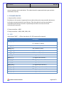
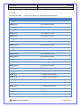
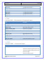
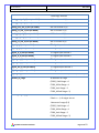
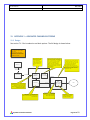
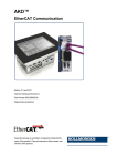
1
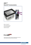
IG2 User Manual
Rev. 1.0.0
10/29/2014
2014
IG2
IG2 User Manual
PYRAMID TECHNICAL CONSULTANTS, INC.
C. PENDLETON
VERSION 2.4.2
Pyramid Technical Consultants
Page 1 of 33
Rev. 1.0.0
IG2 User Manual
10/29/2014
IG2
DATE SUBMITTED: 10/29/2014
DOCUMENT NAME: IG2 User Manual
REVISION NUMBER: 2.4.2
AUTHOR: Christopher J. Pendleton
PROJECT NAME: IG2
PURPOSE: Design
NOTE: The information in this document is the property of Pyramid Technical Consultants, Inc. and should not
be reproduced, printed, copied, or distributed in any manner without permission. If a document number has
been assigned above then the document is controlled and can be found in the Pyramid SharePoint document
repository.
Pyramid Technical Consultants
Page 2 of 33
Rev. 1.0.0
IG2 User Manual
10/29/2014
IG2
1. GENERAL INFORMATION
1.1 Document Approval
This document has been reviewed and approved by the following individuals:
NAME AND PROJECT FUNCTION
DIGITAL SIGNATURE
Christopher J. Pendleton
Director, Software Development
William Nett
Executive Vice President
Jeremy Iken
Software Engineer
1.2 Revision History
Version
Date
Author(s)
Comments
1.1.0
October 3, 2013
C. Pendleton
Added “noscale” wires to BPM
1.2.0
October 16, 2013
C. Pendleton
1.3.0
November 7, 2013
C. Pendleton
Added supported device types (H10,
F460, B10, N2400, I128)
Added F460 I/O
1.4.0
November 21, 2013
C. Pendleton
Added memblock type
1.5.0
December 30, 2013
C. Pendleton
Added I128 I/O
2.0.0
January 7, 2014
C. Pendleton
2.0.1
February 16, 2014
C. Pendleton
Added F460 I/O, I128 bug fixes, renamed
document
I128 bug fixes, added I/O
Added C400 as a supported device
Added asciiclient and kollmorgen devices
Added C400 I/O
2.1.0
March 13, 2014
C. Pendleton
Added Keithley 238 GPIB support
2.2.0
April 8, 2014
C. Pendleton
Added IC101 support
Pyramid Technical Consultants
Page 3 of 33
Rev. 1.0.0
IG2 User Manual
10/29/2014
IG2
Added IC101 I/O
2.3.0
September 16, 2014
C. Pendleton / J. Modified kollmorgen device
Iken
Modified F460 device
Added H20 device
2.4.0
September 30, 2014
C. Pendleton
Added channel buffering
2.4.1
October 9, 2014
J. Iken
Added F100
Added H20 I/O
2.4.2
October 29, 2014
J. Iken
Added I128 I/O
1.3 Reference documents
Document
Rev
Author(s)
Comments
2. CONTENTS
1.
General Information ............................................................................................................... 3
1.1
Document Approval ......................................................................................................... 3
1.2
Revision History ................................................................................................................ 3
1.3
Reference documents ...................................................................................................... 4
2.
Contents .................................................................................................................................. 4
3.
What is EPICS? ........................................................................................................................ 6
4.
How does IG2 use EPICS?........................................................................................................ 6
5.
What EPICS software can be used with IG2? .......................................................................... 7
6.
IG2 Usage and Startup ............................................................................................................ 7
7.
IG2 Configuration and CHannels ............................................................................................. 7
8.
7.1.1
Channel Scaling ......................................................................................................... 9
7.1.2
Channel Limits ........................................................................................................... 9
7.1.3
Channel Buffering ..................................................................................................... 9
Supported Device Types and Wires ........................................................................................ 9
Pyramid Technical Consultants
Page 4 of 33
IG2 User Manual
Rev. 1.0.0
10/29/2014
IG2
9.
Pyramid Devices .................................................................................................................... 10
9.1
M10 ................................................................................................................................ 10
9.2
M40 ................................................................................................................................ 11
9.3
I3200 ............................................................................................................................... 12
9.4
F3200E ............................................................................................................................ 12
9.5
F460 ................................................................................................................................ 15
9.6
C400................................................................................................................................ 19
9.7
B10.................................................................................................................................. 20
9.8
N2400 ............................................................................................................................. 21
9.9
H10 ................................................................................................................................. 21
9.10
H20 ................................................................................................................................. 21
9.11
I128 ................................................................................................................................. 23
9.12
IC101............................................................................................................................... 27
9.13
F100 ................................................................................................................................ 27
10.
Virtual Devices ................................................................................................................... 28
10.1
MEMBLOCK .................................................................................................................... 28
10.2
BPM (Detector)............................................................................................................... 29
10.3
ASCIICLIENT .................................................................................................................... 30
10.4
KOLLMORGEN ................................................................................................................ 30
10.5
KEITHLEY ......................................................................................................................... 31
11.
Appendix 1 – Advanced Channel Buffering ....................................................................... 32
11.1
Design ............................................................................................................................. 32
11.2
Global Options ................................................................................................................ 33
Pyramid Technical Consultants
Page 5 of 33
IG2 User Manual
Rev. 1.0.0
10/29/2014
IG2
3. WHAT IS EPICS?
From the EPICS website (http://www.aps.anl.gov/epics/index.php):
“EPICS is a set of software tools and applications which provide a software infrastructure for
use in building distributed control systems to operate devices such as Particle Accelerators,
Large Experiments and major Telescopes. Such distributed control systems typically comprise
tens or even hundreds of computers, networked together to allow communication between
them and to provide control and feedback of the various parts of the device from a central
control room, or even remotely over the internet.
EPICS uses Client/Server and Publish/Subscribe techniques to communicate between the
various computers. Most servers (called Input/Output Controllers or IOCs) perform real-world
I/O and local control tasks, and publish this information to clients using the Channel Access (CA)
network protocol. CA is specially designed for the kind of high bandwidth, soft real-time
networking applications that EPICS is used for, and is one reason why it can be used to build a
control system comprising hundreds of computers.”
4. HOW DOES IG2 USE EPICS?
IG2 includes an optional Channel Access Server (CAS), or Portable Server, that implements
EPICS Channel Access Protocol. This allows any EPICS client software to readback and control
IG2 I/O points using EPICS Process Variables (PVs).
IG2 has a database of named I/O points, called channels, listed in its configuration file (default:
system.xml). Each of these channels has an associated type and direction. These channels map
one-to-one to EPICS PVs made available by IG2. This list of channels represents the full list of
EPICS PVs available.
This hardware configuration file contains a section for virtual devices that allows the EPICS CAS
to be enabled in IG2. To enable the EPICS CAS in IG2, add the following <epicscas> node to the
<interpreter> section of the file.
### system.xml
<interpreter>
<devices>
<epicscas type=”epicscas” name=”epics_server” />
Pyramid Technical Consultants
Page 6 of 33
Rev. 1.0.0
IG2 User Manual
10/29/2014
IG2
</devices>
</interpreter>
###
5. WHAT EPICS SOFTWARE CAN BE USED WITH IG2?
Almost any EPICS software tool can be used with IG2. There is a vast selection of canned tools
and programming APIs available. Many of them can be found on the EPICS website:
http://www.aps.anl.gov/epics/extensions/index.php. There is support for C/C++, Java, LabView,
Matlab, Perl, Python, C#, PHP, and other languages. There are canned tools for backup/restore,
archiving, plotting, and monitoring.
Any EPICS client that need to communicate with IG2 must be in the same network broadcast
domain as IG2.
6. IG2 USAGE AND STARTUP
IG2 is a console application that takes one command line argument for the path of the xml
configuration file. Example:
ig2-2.0.2 c:\config\mysystem.xml
The configuration file path argument is optional. IG2 will use “system.xml” by default, located
in the local application directory.
7. IG2 CONFIGURATION AND CHANNELS
The system.xml file contains a listing of the hardware configuration that IG2 will manage. This
configuration is user-specific. IG2 offers a set of device types that can be controlled. A set of I/O
points, called wires, is available within an instance of each of these device types. Users can
define an arbitrary number of channels within the device instance which map to a specified
wire to provide control and readback.
### system.xml
<board type="M10" name="XQ7_ctrl" address="7">
<channels>
<channel name="c_XQ7_current_ctrl" wire="analog_out_1" limitLow="-10" limitHigh="10" />
<channel name="r_XQ7_current_ctrl" wire="analog_in_1" scaleB=”2” scaleC=”1” />
Pyramid Technical Consultants
Page 7 of 33
Rev. 1.0.0
IG2 User Manual
10/29/2014
IG2
<channel name="r_XQ7_thermalok" wire="digital_in_1" />
<channel name="c_XQ7_remote" wire="digital_out_2" />
</channels>
</board>
###
The above example shows an M10. The main node is a <board> with attributes that specifies it
as an M10 named XQ7_ctrl at address 7. Channels names are arbitrary, but must be unique.
There are 4 channels defined, and each has a specified M10 wire. Channel “r_XQ7_current_ctrl”
is connected to M10 wire “analog_in_1”. This wire correspond to the physical M10 ADC channel
1. The data type of the wire is embedded in the first part of the wire name. The direction is also
embedded in the wire name, after the data type. A table of supported data types and directions
is listed below. The “xxx” part of the wire name is specific to the device that the wire is assigned
to.
Wire name
analog_in_xxx
analog_out_xxx
int_in_xxx
int_out_xxx
digital_in_xxx
digital_out_xxx
variant_in_xxx
variant_out_xxx
analog[n]_in_xxx
analog[n]_out_xxx
string_in_xxx
(not supported with IG2/EPICS)
string_out_xxx
(not supported with IG2/EPICS)
Data Type
Double precision float (64 bit)
Double precision float (64 bit)
Integer (32 bit)
Integer (32 bit)
Integer (32 bit)
0=false, non-zero=true
Integer (32 bit)
0=false, non-zero=true
Array of Double precision floats
(64 bit)
Array of Double precision floats
(64 bit)
Array of Double precision floats
(64 bit) of length n
Array of Double precision floats
(64 bit) of length n
Null-terminated string
User Access
Read only
Read/Write
Read only
Read/Write
Read
Null-terminated string
Read/Write
Read/Write
Read
Read/Write
Read
Read/Write
Read
Table 1 - Supported Data Types and User Access
Pyramid Technical Consultants
Page 8 of 33
Rev. 1.0.0
IG2 User Manual
10/29/2014
IG2
7.1.1 Channel Scaling
Channels have optional scale factors to convert between user units and device units. These
scale factors apply only to analog data types. This can be seen in the above M10 channel
example. The channel “r_XQ7_current_ctrl” specifies 2 scale factor attributes – “scaleB” and
“scaleC”. These correspond to a linear scaling with the following relationship.
<!-- y = Bx + C, where y=user units, and x=device units -->
These scale factors are optional. If not specified in the channel node, scaleB=1 and scaleC=0.
7.1.2 Channel Limits
Channels have optional upper and lower limits. These limits apply only to analog output types,
and are in user units. This can be seen in the above M10 channel example. The channel
“c_XQ7_current_ctrl” specifies 2 limit attributes – “limitLow” and “limitHigh”. This channel
cannot be set to a value lower than limitLow or higher than limitHigh. These limits are set
independently of the physical limits on the device. For a description of each physical Pyramid
device, see the device data sheet and manual at http://ptcusa.com/products.html.
7.1.3 Channel Buffering
EPICS buffering is limited, and high-rate updates due to the processing of burst device data can
cause data loss. IG2 features additional buffering controls designed to control flow of this type
of data into the EPICS layer. The full design and advanced options are shown in Appendix 1.
To enable sample buffering on an individual channel, modify the channel node in the XML
configuration file to contain the optional aMax parameter:
<channel name=”bufferedchn” wire=”analog_in_1” aMax=”50” />
Set aMax to the maximum size of the device’s buffered acquisition to ensure that data is not
lost. It can likely be set lower than this, as the throughput of an individual channel depends on
several factors including client performance and overall number of channels in the system.
aMax is an optional parameter and defaults to 0 (unbuffered).
8. SUPPORTED DEVICE TYPES AND WIRES
The system.xml hardware configuration is separated into 2 main sections, or nodes. The first is
<loopcontrollers>. This section contains a complete listing of standard Pyramid hardware
devices in the system. The other section is called <interpreter>. This section contains a listing of
Pyramid Technical Consultants
Page 9 of 33
Rev. 1.0.0
IG2 User Manual
10/29/2014
IG2
custom hardware and virtual devices. The tables below list supported device types and their
associated i/o (wires).
9. PYRAMID DEVICES
( <loopcontroller> section)
Each device in this section is supported in some device hierarchy. Loop controller devices can
be directly communicated with over Ethernet. Fiber slave devices must be paired with a
compatible Pyramid loop controller. Pyramid loop controllers can have one of two
communication protocols.
G1 loop controllers = A500
G2 loop controllers = A560, A360, F460, I128
9.1 M10
<board type="M10" … > (Fiber slave device, G1, G2 loopcontroller support)
Wire
Description
digital_out_initiate
Initiate command
(1 = Initiate, 0 = Abort)
analog_in_1
ADC channel 1 (volts)
analog_in_2
ADC channel 2 (volts)
analog_out_1
DAC channel 1 (volts)
analog_out_2
DAC channel 2 (volts)
digital_in_1
TTL digital input channel 1
digital_in_2
TTL digital input channel 2
digital_in_3
TTL digital input channel 3
digital_in_4
TTL digital input channel 4
digital_out_1
TTL digital output channel 1
digital_out_2
TTL digital output channel 2
digital_out_3
TTL digital output channel 3
digital_out_4
TTL digital output channel 4
Pyramid Technical Consultants
Page 10 of 33
Rev. 1.0.0
IG2 User Manual
10/29/2014
IG2
9.2 M40
<board type="M40" … > (Fiber slave device, G1, G2 loopcontroller support)
Wire
Description
analog_in_1
ADC channel 1 (volts)
analog_in_2
ADC channel 2 (volts)
analog_in_3
ADC channel 3 (volts)
analog_in_4
ADC channel 4 (volts)
analog_in_5
ADC channel 5 (volts)
analog_in_6
ADC channel 6 (volts)
analog_in_7
ADC channel 7 (volts)
analog_in_8
ADC channel 8 (volts)
analog_out_1
DAC channel 1 (volts)
analog_out_2
DAC channel 2 (volts)
analog_out_3
DAC channel 3 (volts)
analog_out_4
DAC channel 4 (volts)
analog_out_5
DAC channel 5 (volts)
analog_out_6
DAC channel 6 (volts)
analog_out_7
DAC channel 7 (volts)
analog_out_8
DAC channel 8 (volts)
digital_in_1
TTL digital input channel 1
digital_in_2
TTL digital input channel 2
digital_in_3
TTL digital input channel 3
digital_in_4
TTL digital input channel 4
digital_in_5
TTL digital input channel 5
digital_in_6
TTL digital input channel 6
digital_in_7
TTL digital input channel 7
digital_in_8
TTL digital input channel 8
digital_out_1
TTL digital output channel 1
digital_out_2
TTL digital output channel 2
Pyramid Technical Consultants
Page 11 of 33
Rev. 1.0.0
IG2 User Manual
10/29/2014
IG2
digital_out_3
TTL digital output channel 3
digital_out_4
TTL digital output channel 4
digital_out_5
TTL digital output channel 5
digital_out_6
TTL digital output channel 6
digital_out_7
TTL digital output channel 7
digital_out_8
TTL digital output channel 8
9.3 I3200
<board type="I3200" … > (Fiber slave device, G1, G2 loopcontroller support)
Wire
Description
variant_in_current
32-element array of channel data (A)
digital_in_measuring
I3200 measuring mode indicator
analog_in_bias
High voltage readback (volts)
digital_in_actuator_limitA
Actuator limit A readback
digital_in_actuator_limitB
Actuator limit B readback
digital_out_actuator
Actuator position control
analog_out_bias
High voltage control (volts)
analog_out_period
I3200 integration time configuration control
int_out_capacitor
I3200 capacitor configuration control (0 or 1)
digital_out_initiate
I3200 initiate acquisition control
9.4 F3200E
<board type="F3200E" … > (G2 loopcontroller support)
Wire
Description
variant_in_data
32 elements of channel data (A)
1 element of sample info A (bit convert to int)
1 element of sample info B (bit convert to int)
4 elements of ADC
3 elements of DAC command
Pyramid Technical Consultants
Page 12 of 33
Rev. 1.0.0
IG2 User Manual
10/29/2014
IG2
1 overrange bitmask
analog_out_adc_1 (not yet added)
ADC out channel 1 (V)
analog_out_adc_2 (not yet added)
ADC out channel 2 (V)
analog_out_adc_3 (not yet added)
ADC out channel 3 (V)
analog_in_adc_1 (not yet added)
ADC in channel 1 (V)
analog_in_adc_2 (not yet added)
ADC in channel 2 (V)
analog_in_adc_3 (not yet added)
ADC in channel 3 (V)
analog_in_adc_4 (not yet added)
ADC in channel 4 (V)
digital_in_1 (not yet added)
TTL digital input channel 1
digital_in_2 (not yet added)
TTL digital input channel 2
digital_in_3 (not yet added)
TTL digital input channel 3
digital_in_4 (not yet added)
TTL digital input channel 4
digital_out_1 (not yet added)
TTL digital output channel 1
digital_out_2 (not yet added)
TTL digital output channel 2
digital_out_3 (not yet added)
TTL digital output channel 3
digital_out_4 (not yet added)
TTL digital output channel 4
digital_out_initiate
Initiate measurement (1=initiate, 0 =abort)
variant_in_range
16 elements of range
(F3200_10uA Range = 0
F3200_100uA Range = 1
F3200_1mA Range = 2
F3200_100mA Range = 3)
variant_out_range_set
1 element of bank (1-16)
If bank == -1, all ranges are set
1 element of range (0-3)
(F3200_10uA Range = 0
F3200_100uA Range = 1
F3200_1mA Range = 2
F3200_100mA Range = 3)
Pyramid Technical Consultants
Page 13 of 33
Rev. 1.0.0
IG2 User Manual
10/29/2014
IG2
digital_out_buffered_acquisition
Buffer Contiguous Data
(1 = Enable, 0 = Disable)
int_out_acquisition_mode
Acquisition mode (0-7)
(F3200_CustomAcquisitionMode = 0,
F3200_InternalAcquisitionMode = 1,
F3200_ExternalStartAcquisitionMode = 2,
F3200_ExternalStartStopAcquisitionMode = 3,
F3200_ExternalStartHoldAcquisitionMode = 4,
F3200_ExternalWindowedAcquisitionMode =
5,
F3200_SweepMode = 6
F3200_EncoderDrivenMode = 7)
int_out_adc_rate
ADC rate (Hz)
int_out_conversions_per_sample
Conversions per sample
int_out_start_trigger_source
int_out_stop_count
Start trigger source (0-3)
(InternalTriggerSource = 0,
BNCTriggerSource = 1,
OpticalTriggerSource,
BNC_and_OpticalTriggerSource)
Start trigger source (0-3)
(InternalTriggerSource = 0,
BNCTriggerSource = 1,
OpticalTriggerSource,
BNC_and_OpticalTriggerSource)
Start trigger source (0-3)
(InternalTriggerSource = 0,
BNCTriggerSource = 1,
OpticalTriggerSource,
BNC_and_OpticalTriggerSource)
Stop Count
int_out_register_offset
Offset from base_address to read or write
int_out_register_contents
Contents read from address, or contents to
write to address
int_out_base_address
Base address (initialized as 0x08810000)
int_out_pause_trigger_source
int_out_stop_trigger_source
Pyramid Technical Consultants
Page 14 of 33
Rev. 1.0.0
IG2 User Manual
10/29/2014
IG2
digital_out_register_command
Get register at address or Set register address
with contents (1 = set, 0 = get)
9.5 F460
<loopcontroller type="F460" … > (G2 loop controller, direct support)
Wire
Description
analog_in_1
ADC channel 1 (volts)
analog_in_2
ADC channel 2 (volts)
analog_in_current_1
Current channel 1 (A)
analog_in_current_2
Current channel 2 (A)
analog_in_current_3
Current channel 3 (A)
analog_in_current_4
Current channel 4 (A)
analog_in_channel_1
Current channel 1 w/sensor compensations
(A)
analog_in_channel_2
Current channel 2 w/sensor compensations
(A)
analog_in_channel_3
Current channel 3 w/sensor compensations
(A)
analog_in_channel_4
Current channel 4 w/sensor compensations
(A)
analog_in_x_pos
Calculated x position
analog_in_y_pos
Calculated y position
analog_in_bias
Voltage
analog_in_process_value
Process value (servo)
analog_in_process_target
Process target (servo)
variant_in_data
4 elements of current data
4 elements of channel data
1 element of xpos
1 of ypos
4 elements of analog in data
Pyramid Technical Consultants
Page 15 of 33
Rev. 1.0.0
IG2 User Manual
10/29/2014
IG2
4 elements of analog out data
1 element of high voltage
digital_out_initiate
Initiate measurement (1=initiate, 0 =abort)
int_out_range_1
Channel 1 range (0-3)
(F460_1uA_Range = 0,
F460_10uA_Range = 1,
F460_100uA_Range = 2,
F460_1mA_Range = 3)
int_out_range_2
Channel 2 range (same as channel 1)
int_out_range_3
Channel 3 range (same as channel 1)
int_out_range_4
Channel 4 range (same as channel 1)
int_out_monitor
Monitor out mode (0-3)
(F460_Current = 0,
F460_Sensor = 1,
F460_Position = 2,
F460_ManualOutput = 3)
analog_out_1
Analog out channel 1 (V)
analog_out_2
Analog out channel 2 (V)
analog_out_3
Analog out channel 3 (V)
analog_out_4
Analog out channel 4 (V)
analog_out_bias
External bias (V)
analog_out_integration_time
Integration time (seconds)
analog_out_dac_low_limit
DAC low limit (servo)
analog_out_dac_high_limit
DAC high limit (servo)
analog_out_kp
Kp PID parameter (servo)
analog_out_ki
Ki PID parameter (servo)
analog_out_low_current_limit
Low current limit (servo)
analog_out_reference
Reference (servo)
int_out_servo_period
Servo period (microseconds)
Pyramid Technical Consultants
Page 16 of 33
Rev. 1.0.0
IG2 User Manual
10/29/2014
IG2
int_out_servo_mode
Servo mode (1-7, see device manual)
digital_out_servo_enable
Servo enable (1=enable, 0=disable)
int_out_register_offset
Offset from base_address to read or write
int_out_register_contents
Contents read from address, or contents to
write to address
digital_out_register_command
Get register at address or Set register address
with contents (1 = set, 0 = get)
int_out_base_address
Base address (initialized as 0x08810000)
string_in_firmware
Firmware Version
string_in_fpga
FPGA Version
string_in_serial_num
Serial Number
string_in_software_rev
Software Revision
string_in_secondary_fpga
Secondary FPGA Version
string_in_rtp_rev
RTP Revision
string_in_hardware_rev
Hardware Revision
int_out_position_calculation
(1 = Split Calculation, 0 = Quadrant Calculation
)
digital_out_buffered_acquisition
Buffer Contiguous Data
(1 = Enable, 0 = Disable)
int_out_acquisition_mode
Acquisition mode (0-5)
(F460_CustomAcquisitionMode = 0,
F460_InternalAcquisitionMode = 1,
F460_ExternalStartAcquisitionMode = 2,
F460_ExternalStartStopAcquisitionMode = 3,
F460_ExternalStartHoldAcquisitionMode = 4,
F460_ExternalWindowedAcquisitionMode = 5)
int_out_start_trigger_source
int_out_pause_trigger_source
Pyramid Technical Consultants
Start trigger source (0-1)
(InternalTriggerSource = 0,
BNCTriggerSource = 1)
Start trigger source (0-1)
(InternalTriggerSource = 0,
BNCTriggerSource = 1)
Page 17 of 33
Rev. 1.0.0
IG2 User Manual
10/29/2014
IG2
int_out_stop_trigger_source
Start trigger source (0-1)
(InternalTriggerSource = 0,
BNCTriggerSource = 1)
int_out_bnc_start_gate
Trigger gate polarity
(1 = Falling edge gate, 0 = Rising edge gate)
int_out_stop_count
Stop Count
int_out_burst_count
Burst Size
int_out_calibration_source
Calibration Source (0-2)
(No Calibration Source = 0,
Internal Low = 1,
Internal High = 2)
int_out_calibration_channel
Channel to receive internal calibration source (0-3)
int_out_calibrate_command
Calibrate Channel (0-3)
digital_out_clear_calibrations
Clear Calibrations
variant_out_hvdac_calibration
3-element array
[valid, gain, offset]
variant_out_hvadc_calibration
3-element array
[valid, gain, offset]
variant_out_calibration_range_1
Calibration for range 1uA
9-element array:
[valid, gain[0], offset[0], …, gain[3], offset[3]]
variant_out_calibration_range_2
Calibration for range 10uA (Same as range 1)
variant_out_calibration_range_3
Calibration for range 100uA (Same as range 1)
variant_out_calibration_range_4
Calibration for range 1mA (Same as range 1)
variant_out_analoginput_calibration
5-element array
[valid, gain[0], offset[0], …, gain[1], offset[1]]
variant_out_analogoutput_calibration
9-element array
[valid, gain[0], offset[0], …, gain[3], offset[3]]
Pyramid Technical Consultants
Page 18 of 33
Rev. 1.0.0
IG2 User Manual
10/29/2014
IG2
9.6 C400
<board type="C400" … > (G2 loop controller, direct support)
Wire
Description
digital_in_running
Running state (1=running, 0=not running)
digital_in_paused
Paused state (1=paused, 0=not paused)
digital_in_stopped
Stopped state (1=stopped, 0=not stopped)
int_in_counts_n
Counts for the 4 channels (n=1-4)
analog_in_rate_n
Rate for the 4 channels (n=1-4)
analog_in_bias_n
Voltage readback for the 4 channels (n=1-4)
digital_out_initiate
Initiate/Abort acquisition control command
(1=initate, 0=abort)
digital_out_polarity_n
Discriminator polarities for the 4 channels
(n=1-4) (1=positive,0=negative)
digital_out_pulse_enable_n
Pulse control for the 4 channels (n=1-4)
(1=enable,0=disable)
int_out_accum_mode
Accumulate mode (0-1)
(C400_SingleIntegrations = 0,
C400_AccumulatedIntegrations = 1)
int_out_trig_buf
Data buffer size
int_out_trig_bur
Burst size
int_out_trig_mode
Trigger mode (0-6)
(C400_CustomAcquisitionMode = 0,
C400_InternalAcquisitionMode = 1,
C400_ExternalStartAcquisitionMode = 2,
C400_ExternalStartStopAcquisitionMode = 3,
C400_ExternalStartHoldAcquisitionMode = 4,
C400_ExternalWindowedAcquisitionMode = 5,
C400_DiscriminatorSweepMode = 6)
int_out_trig_source_start
Start trigger source (0-3)
(InternalTriggerSource = 0,
Pyramid Technical Consultants
Page 19 of 33
Rev. 1.0.0
IG2 User Manual
10/29/2014
IG2
BNCTriggerSource = 1,
OpticalTriggerSource = 2,
BNC_and_OpticalTriggerSource = 3)
int_out_trig_source_stop
Stop trigger source (0-3)
(InternalTriggerSource = 0,
BNCTriggerSource = 1,
OpticalTriggerSource = 2,
BNC_and_OpticalTriggerSource = 3)
int_out_trig_source_pause
Pause trigger source (0-3)
(InternalTriggerSource = 0,
BNCTriggerSource = 1,
OpticalTriggerSource = 2,
BNC_and_OpticalTriggerSource = 3)
int_out_pulse_period
Pulse period (nsec)
int_out_pulse_width
Pulse width (nsec)
analog_out_low_limit_n
Discriminator low level (volts)
analog_out_high_limit_n
Discriminator high level (volts)
analog_out_bias_n
Voltage control for the 4 channels (volts)
analog_out_period
Integration period (sec)
9.7 B10
<board type="B10" … > (Fiber slave device, G1 loop controller support only)
Wire
Description
digital_in_1
TTL digital input channel 1
digital_in_2
TTL digital input channel 2
digital_in_3
TTL digital input channel 3
digital_in_4
TTL digital input channel 4
digital_in_5
TTL digital input channel 5
digital_in_6
TTL digital input channel 6
Pyramid Technical Consultants
Page 20 of 33
Rev. 1.0.0
IG2 User Manual
10/29/2014
IG2
digital_in_7
TTL digital input channel 7
digital_in_8
TTL digital input channel 8
digital_out_1
TTL digital output channel 1
digital_out_2
TTL digital output channel 2
digital_out_3
TTL digital output channel 3
digital_out_4
TTL digital output channel 4
digital_out_5
TTL digital output channel 5
digital_out_6
TTL digital output channel 6
digital_out_7
TTL digital output channel 7
digital_out_8
TTL digital output channel 8
9.8 N2400
<board type="N2400" … > (Fiber slave device, G1 loop controller support only)
Wire
Description
digital_in_mode_switch_n
Mode switch position (n=1-24)
digital_in_relay_switch_n
Relay switch position (n=1-24)
digital_in_limit_neg_n
Limit switch neg state (n=1-24)
digital_in_limit_pos_n
Limit switch pos state (n=1-24)
digital_out_switch_relay_n
Switch relay (n=1-24)
9.9 H10
<board type="H10" … > (Fiber slave device, G1, G2 loopcontroller support)
Wire
Description
analog_in_1
Old probe: dBdT, New probe: voltage
analog_in_2
Field
9.10 H20
<board type="H20" … > (Fiber slave device, G1, G2 loopcontroller support)
Pyramid Technical Consultants
Page 21 of 33
Rev. 1.0.0
IG2 User Manual
10/29/2014
IG2
Wire
Description
analog_in_probe_field_1
Field measured by probe 1 (G)
analog_in_probe_field_2
Field measured by probe 2 (G)
analog_in_probe_temperature_1
Temperature measured by probe 1 (C)
analog_in_probe_temperature_2
Temperature measured by probe 2 (C)
analog_in_adc_1
ADC1 measurement (V)
analog_in_adc_2
ADC2 measurement (V)
analog_out_dac_1
DAC (V)
(Manual Mode Only)
analog_out_dac_2
DAC (V)
(Manual Mode Only)
int_out_range_1
Probe 1 range (integer)
int_out_range_2
Probe 2 range (integer)
int_out_mode_1
Probe 1 mode
Mode_Manual = 0x0,
Mode_Monitor = 0x1,
Mode_DigitalClosedLoop = 0x2,
Mode_AnalogClosedLoop = 0x3,
Mode_FastMonitor = 0x4
int_out_mode_2
Probe 1 mode
(same mapping as mode_out_1)
analog_out_setpoint_1
Field Setpoint (G)
(Digital Closed Loop Mode Only)
analog_out_setpoint_2
Field Setpoint (G)
(Digital Closed Loop Mode Only)
analog_out_averaging_period
Averaging period (s)
int_in_serial_num_1
Probe 1 serial number
int_in_serial_num_2
Probe 2 serial number
analog_in_calib_temp_1
Calibration Temperature
Pyramid Technical Consultants
Page 22 of 33
Rev. 1.0.0
IG2 User Manual
10/29/2014
IG2
analog_in_calib_temp_2
Calibration Temperature
analog_out_proportional_1
Proportional (Kp)
analog_out_proportional_2
Proportional (Kp)
analog_out_outmax_1
Out Max (V)
analog_out_outmax_2
Out Max (V)
digital_out_positive_output_1
Positive only output
( 0 = Positive only disabled
1 = Positive only enabled )
digital_out_positive_output_2
Positive only output
( 0 = Positive only disabled
1 = Positive only enabled )
analog_out_slew_limit_1
Slew Limit (V/s)
analog_out_slew_limit_2
Slew Limit (V/s)
analog_out_setpoint_gain_1
Setpoint Gain (G/V)
(Analog Closed Loop Mode Only)
analog_out_setpoint_gain_2
Setpoint Gain (G/V)
(Analog Closed Loop Mode Only)
analog_out_monitor_gain_1
Analog output gain
analog_out_monitor_gain_2
Analog output gain
9.11 I128
<loopcontroller type="I128" … > (G2 loop controller, direct support)
Wire
Description
variant_in_current
digital_in_measuring
128 elements of channel data (A)
-10000 = overrange
-20000 = unable to convert to A
Measuring readback
analog_in_bias
High voltage readback (volts)
analog_in_hcc
High current channel readback (A)
analog_in_range_current
Range (A)
Pyramid Technical Consultants
Page 23 of 33
Rev. 1.0.0
IG2 User Manual
10/29/2014
IG2
analog_in_range_charge
Range (C)
analog_out_bias
High voltage command (volts)
analog_out_integration_time
Integration time (s)
int_out_conversions_per_sample
Conversions per sample (1-255)
int_out_range_hcc
High current channel range
I128HCC_1uA_Range = 0x0,
I128HCC_5uA_Range = 0x1,
I128HCC_10uA_Range = 0x2,
I128HCC_20uA_Range = 0x3,
digital_out_initiate
Initiate command
(1 = Initiate, 0 = Abort)
digital_out_enable_external_bias
High voltage output (1 = enable, 0 = disable)
int_out_ion_chamber_mode
digital_out_clear_offset_zero
Ion chamber mode
( 0 = Standard Mode
1 = IC Mode)
Ion Chamber Temperature (I)
Ion Chamber Pressure (PSI)
Ion Chamber Humidity (%RH)
Ion Chamber Reference (V)
DAC out 1
DAC out 2
ADC In 1
ADC In 2
Averaging Period
( 25 = 1e-4
250 = 1e-3
2500 = 1e-2
25000 = 1e-1
41675 = 1.667e-1
250000 = 1.0 )
Set the latest data sample as the background
offset vector
Clear the background offset vector
string_in_firmware
Firmware Version
string_in_fpga
FPGA Version
analog_in_ic_temp
analog_in_ic_pressure
analog_in_ic_humidity
analog_in_ic_reference
analog_out_dac_1
analog_out_dac_2
analog_in_adc_1
analog_in_adc_2
analog_out_averaging_period
digital_out_zero_offset
Pyramid Technical Consultants
Page 24 of 33
Rev. 1.0.0
IG2 User Manual
10/29/2014
IG2
string_in_serial_num
Serial Number
string_in_software_rev
Software Revision
string_in_secondary_fpga
Secondary FPGA Version
string_in_rtp_rev
RTP Revision
string_in_hardware_rev
Hardware Revision
int_out_filter
HCC Filter
digital_out_combine_channels
HCC Combine Channels Enable
analog_out_monitor_charge
HCC Monitor Charge
digital_out_align_channel_data
HCC Align with Channel Data Enable
analog_out_target_dose
digital_out_beam_enable
Target Charge (nC)
(This and next wire should be tested
thoroughly)
Enable Beam
digital_in_beam_enabled
( 1 = enabled, 0 = disabled)
analog_in_hcc_processed
HCC data in Amps. May be processed
(filtered)
digital_in_hcc_target_reached
(1 = target reached)
analog_in_hcc_dose
FPGA2 v1.4.10 and later: Dose accumulated on
the HCC in coulombs.
FPGA2 v1.4.9 and earlier: HCC dose remaining
in coulombs.
int_out_start_trigger_source
Start trigger source (0-1)
(InternalTriggerSource = 0,
BNCTriggerSource = 1)
Start trigger source (0-1)
(InternalTriggerSource = 0,
BNCTriggerSource = 1)
Start trigger source (0-1)
(InternalTriggerSource = 0,
BNCTriggerSource = 1)
int_out_pause_trigger_source
int_out_stop_trigger_source
int_out_bnc_start_gate
int_out_stop_count
Trigger gate polarity
(1 = Falling edge gate, 0 = Rising edge gate)
Stop Count
int_out_burst_count
Burst Size
int_out_register_offset
Offset from base_address to read or write
Pyramid Technical Consultants
Page 25 of 33
Rev. 1.0.0
IG2 User Manual
10/29/2014
IG2
int_out_register_contents
Contents read from address, or contents to
write to address
digital_out_register_command
Get register at address or Set register address
with contents (1 = set, 0 = get)
int_out_base_address
Base address (initialized as 0x08810000)
int_in_interlock_readbacks
digital_out_relay_enable
Bit encoded readback of interlock status
(Least significant bits first)
cmd:8;
reserved1:1;
reserved2:1;
// High when CPLD is in fault state
fault:1;
enable_in:1;
//Reflects the state of the Enabled line, as
determined by the commands sent
enabled:1;
// High if the CPLD has failed
cpld_stat_A:1;
// High if the CPLD has failed
cpld_stat_B:1;
// Reflects the key switch state (high for Diag)
keyswitch:1;
// command sent for diag mode
diag_mode:1;
// High when relay is closed
interlock_status:1;
// Reflects the intended state of the relay, as
determined by the commands sent
interlock_command:1;
// High when the CPLD should be in the initial
state
initial_state:1;
reserved3:4;
relay_command:1;
reserved4:7;
( 1 = enable, 0 = disable)
digital_out_actuator_enable
( 1 = enable, 0 = disable)
digital_out_test_ab
( 0 = Test A, 1 = Test B)
no readback
( 0 = Enable, 1 = Disable)
digital_out_interlock_enable
Pyramid Technical Consultants
Page 26 of 33
Rev. 1.0.0
IG2 User Manual
10/29/2014
IG2
digital_out_calibration_source
int_out_calibration_current_channel
analog[260]_out_current_calibration
digital_out_buffered_acquisition
no readback
Calibration Source
I128_NoCalibrationSource = 0,
I128_InternalCalibrationSource = 1,
Calibration channel (1-129)
1-128 = strip select
129 = HCC
4 elements of valid (128 bits), followed by
gain/offset pairs
[valid x4, gain[0], offset[0], …, gain[127],
offset[127]]
Buffer Contiguous Data
(1 = Enable, 0 = Disable)
9.12 IC101
<board type="IC101" … > (Fiber slave device, G1, G2 loopcontroller support)
Wire
Description
analog_in_current
Current input (A)
analog_in_accumulated_charge
Accumulated charge (C)
analog_out_range
Range select (A)
digital_out_initiate
Initiate command
digital_out_accumulate_charge
Accumulate command (1=start accumulation,
0=stop accumulation)
9.13 F100
<board type="F100" … > (Fiber slave device, G1, G2 loopcontroller support)
Wire
Description
analog_in_1
Current input (A)
digital_out_initiate
Initiate measurement (1=initiate, 0 =abort)
int_out_range
Range select (0-16)
Sixteen total, thirteen unique
( 0=auto
1 = 1 µA
2 = 2 µA
Pyramid Technical Consultants
Page 27 of 33
Rev. 1.0.0
IG2 User Manual
10/29/2014
IG2
3 = 5 µA
4 = 10 µA
5 = 10 µA
6 = 20 µA
7 = 50 µA
8 = 100 µA
9 = 100 µA
10 = 200 µA
11 = 500 µA
12 = 1 mA
13 = 1 mA
14 = 2 mA
15 = 5 mA
16 = 10 mA )
10. VIRTUAL DEVICES
( <interpreter> section )
Each device in this section is a custom or virtual device and is directly supported through IG2.
10.1 MEMBLOCK
<memblock type="memblock" size=”n” … >
Wire
Description
analog_out_n
General use analog output. (n=1-512)
digital_out_n
General use digital output. (n=1-512)
int_out_n
General use integer output. (n=1-512)
string_out_n
General use string output. (n=1-512)
analog_in_n
General use analog input. (n=1-512)
digital_in_n
General use digital input. (n=1-512)
int_in_n
General use integer input. (n=1-512)
string_in_n
General use string input. (n=1-512)
Pyramid Technical Consultants
Page 28 of 33
Rev. 1.0.0
IG2 User Manual
10/29/2014
IG2
10.2 BPM (Detector)
<detector type="bpm" … >
X AXIS = Channels 17-32
Y AXIS = Channels 1-16
Wire
Description
digital_out_position
Position control (0=out, non-zero=in)
analog_out_bias
High voltage control (V)
analog_in_bias
High voltage readback (V)
int_in_position
Position readback (0=out, non-zero=in)
analog_in_xcurrent_noscale
X-axis current readback (A)
This value = sum of the X axis channels.
analog_in_ycurrent_noscale
Y-axis current readback (A)
This value = sum of the Y axis channels.
analog_in_beamcurrent_noscale
Beam current readback (A)
This value = (sum of X axis channels + sum of Y
axis channels) / 2
analog_in_xcurrent
X-axis current readback (variable units,
autoscaled)
See analog_in_xcurrent_noscale.
analog_in_ycurrent
Y-axis current readback (variable units,
autoscaled)
See analog_in_ycurrent_noscale.
analog_in_beamcurrent
Beam current readback (variable units,
autoscaled)
See analog_in_beamcurrent_noscale.
variant_in_channels
32-element array of channel data (A)
analog_in_xpos_actual
Calculated x-axis position readback (mm)
Gaussabola algorithm. Returns -10000 when
calue cannot be calculated.
analog_in_ypos_actual
Calculated y-axis position readback (mm)
Gaussabola algorithm. Returns -10000 when
calue cannot be calculated.
Pyramid Technical Consultants
Page 29 of 33
Rev. 1.0.0
IG2 User Manual
10/29/2014
IG2
analog_in_width_actual
Calculated x-axis width readback (mm)
Gaussabola algorithm. Returns -10000 when
calue cannot be calculated.
analog_in_height_actual
Calculated y-axes width readback (mm)
Gaussabola algorithm. Returns -10000 when
calue cannot be calculated.
analog_in_xpos_target
Target x-axis position (not currently used)
analog_in_ypos_target
Target y-axis position (not currently used)
analog_in_width_target
Target x-axis width (not currently used)
analog_in_height_target
Target y-axis width (not currently used)
10.3 ASCIICLIENT
<asciiclient type=" asciiclient " ip=”TODO” port=”TODO” proto=”TODO” … >
Wire
Description
string_out_message
String sent to device
string_in_response
Response received from device
int_in_status
TODO
string_in_error_description
TODO
10.4 KOLLMORGEN
< kollmorgentype=" kollmorgen" telnet_write_chn=”TODO” telnet_read_chn=”TODO”
telnet_status_chn=”TODO” telnet_error_chn=”TODO” … >
Wire
Description
analog_out_position
MP.P (float)
int_out_table
MT.TNUM (integer)
int_out_profile
MT.CNTL (integer)
int_out_task
MT.NUM (integer)
int_out_cmdsource
DRV.CMDSOURCE (integer)
int_out_opmode
DRV.OPMODE (integer)
Pyramid Technical Consultants
Page 30 of 33
Rev. 1.0.0
IG2 User Manual
10/29/2014
IG2
digital_out_stop
DRV.STOP (no argument)
digital_out_move
MT.MOV (no argument)
digital_out_home
HOME.MOV (no argument)
digital_out_enable
DRV.DIS + DRV.ENA (no argument)
analog_in_position
PL.FB
int_in_status
TODO
string_in_error_description
TODO
10.5 KEITHLEY
(manufacturing build only)
<keithley type="keithley" name="k238" id="0" address="16" >
Wire
Description
int_out_sourcemode
Source mode configuration (0=voltage,
1=current).
analog_out_sourcelevel
Source setpoint configuration.
analog_out_compliancevoltage
Compliance voltage configuration.
digital_out_initiate
Set operational mode (0=stop,1=run).
digital_in_error
Error state of last command sent (0=no error,
1=error).
string_out_command
Send string command. Max 40 characters.
Pyramid Technical Consultants
Page 31 of 33
Rev. 1.0.0
IG2 User Manual
10/29/2014
IG2
11. APPENDIX 1 – ADVANCED CHANNEL BUFFERING
11.1 Design
See section 7.1.2 for introduction and basic options. The full design is shown below:
The EPICS event queue is prone to overflow
and drop data due to high-rate updates
from IG2 objects.
This diagram illustrates the buffering
technique used to prevent the event queue
from overflowing, and prevent data loss.
C. Pendleton Sept. 19, 2014
BufferA exists at the epicspv
object level (1 per epicspv
object). Size <= Amax. Amax
is set per defined XML
channel. This value is set to
a global default and can be
overriden at the channel
level.
Data Source
Memory Queue exists at the epicspv object
level (1 per epicspv object). This handles
gdd memory management. Amax+Bmax gdd
object are allocated at startup. A gdd object
is taken off the head of the queue when
requested by clientUpdate(). It is then
added to the tail before it is added to
BufferA. The size of this queue ensures that
the gdd object at the head is not in use (in
BufferA or BufferB).
epicspv
updateChannels()
PTCChannelG2
clientUpdate()
BufferA
(synchronized
queue, size <=
Amax)
The EPICS CAS library provides limited ways
of determining whether all samples on the
event queue have been sent to a client. We
will use (subscriptionEventsPosted() subscriptionEventsProcessed()) to
determine how many events are on the
event queue. There is a possibility that there
are events in subscriptionEventsPosted()
that will never be processed. This will cause
problems if it is true.
Memory Queue
(size = Amax+Bmax)
EPICS library
Active Object
postEvent()
clientUpdate() will check if there is room on
BufferA (size < Amax). If yes, then it will add
the sample. If no, then it will drop the
sample. If Amax==0, then the single sample
in BufferA will be overwritten.
The AO is static (only 1). The epicspv object
clientUpdate() will request that the AO service
BufferA. These requests will be processed serially,
in a queued manner.
Pyramid Technical Consultants
The AO will block until BufferB has
room (size < Bmax), and transfer
the sample on BufferA to BufferB.
Bmax is a global parameter.
BufferB
(EPICS event queue,
size <= Bmax)
EPICS
The EPICS event queue. We will
control how many samples are
put on this. Size <= Bmax.
Page 32 of 33
Rev. 1.0.0
IG2 User Manual
10/29/2014
IG2
11.2 Global Options
There are 2 global buffering options:
<epicscas name=”ecas” aMax=”10” bMax=”20” />
aMax is an optional parameter that determines the global value that all channels will default to.
This can be overridden at the channel level (see 7.1.2). The default value of this parameter is 0
(unbuffered).
bMax determines the maximum allowed number of samples on the EPICS event queue.
Changing this is not recommended. The default value is 10.
Pyramid Technical Consultants
Page 33 of 33