1
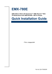
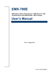
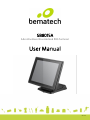
SB8015A All-in-One Bezel Free Android POS Terminal User Manual User Manual Ver 1.0 How to Use This Manual This manual contains information to set up and use the SB8015A. In addition, instructions are included for added hardware, software, upgrades, and optional items. Chapter 1 An introduction to what you find in the box and an overview of product specifications, appearance, and interface. Chapter 2 Disassembling the unit for upgrade or maintenance. Chapter 3 Mounting procedures for optional devices, such as MSR,VFD. Chapter 4 & 5 Motherboard information. WARNING! Text set off in this manner indicates that failure to follow directions could result in bodily harm or loss of life. CAUTION: Text set off in this manner indicates that failure to follow directions could result in damage to equipment or loss of information. NOTE: Text set off in this manner provides important supplemental information. Before installing and operating the unit, please read this user manual thoroughly and retain for reference. Federal Communications Commission (FCC) Notice This equipment has been tested and found to comply with the limits for a Class A digital device, pursuant to Part 15 of the FCC Rules. These limits are designed to provide reasonable protection against harmful interference in a residential installation. This equipment generates, uses, and can radiate radio frequency energy and, if not installed and used in accordance with the instructions, may cause harmful interference to radio communications. However, there is no guarantee that interference will not occur in a particular installation. If this equipment does cause harmful interference to radio or television reception, which can be determined by turning the equipment off and on, the user is encouraged to try to correct the interference by one or more of the following measures: Reorient or relocate the receiving antenna. Increase the separation between the equipment and the receiver. Connect the equipment to an outlet on a circuit different from that to which the receiver is connected. Consult the dealer or an experienced radio/TV technician for help. NOTE: Shielded interconnect cables and shielded AC power cables must be employed with this equipment to insure compliance with pertinent RF emission limits governing this device. Changes or modifications not expressly approved by the system’s manufacturer could void the user’s authority to operate the equipment. This device complies with Part 15 of the FCC Rules. Operation is subject to the following two conditions: 1. This device may not cause harmful interference. 2. This device must accept any interference received, including interference that may cause undesired operation. Copyright The information in this guide is subject to change without prior notice. The manufacturer shall not be liable for technical or editorial errors or omissions contained herein, nor for incidental or consequential damages resulting from the furnishing, performance, or use of this material. This manual contains information protected by copyright. No part of this manual may be photocopied or reproduced in any form without prior written consent from the manufacturer. The software described in this guide is furnished under a license agreement or nondisclosure agreement. The software may be used or copied only in accordance with the terms of the agreement. Product names mentioned herein may be trademarks and/or registered trademarks of their respective companies. © 2015 All rights reserved. Precautions 1. Please read these safety instructions carefully. 2. Keep this User Manual for later reference. 3. Disconnect this equipment from the AC outlet before cleaning. Do not use liquid or spray detergent for cleaning. Use only a moistened sheet or cloth. 4. For pluggable equipment, the socket outlet should be installed near the equipment and should be easily accessible. 5. Avoid humidity and moisture. 6. Install equipment on a stable surface. 7. Do not leave this equipment running in an enclosed or non-air-circulated environment, nor store in temperatures above 60°C. Such conditions may damage the equipment. 8. Ventilation openings on the unit are for air circulation and protect the equipment from overheating. DO NOT COVER THE OPENINGS. 9. Check the voltage of the power source before connecting the equipment to the power outlet. 10. Place the power cord so that it will not be stepped on. Do not place anything over the power cord. The power cord must be rated for the product and for the voltage and current marked on the product’s electrical ratings label. The voltage and current rating of the cord should be greater than the voltage and current rating marked on the product. 11. All cautions and warnings on the equipment should be noted. 12. If the equipment is not used for a long time, disconnect the equipment from the power outlet to avoid damage. 13. Never allow any liquid into ventilation openings. This could cause fire or electrical shock. 14. Never open the equipment. For safety reasons, qualified service personnel should only open the equipment. 15. If one of the following situations may arise, get the equipment checked by qualified service personnel: a. The power cord or plug is damaged. b. Liquid has penetrated the equipment. c. The equipment has been exposed to moisture. d. The equipment does not work well or you cannot get it work according to the user manual. e. The equipment has been dropped and damaged. f. The equipment has obvious signs of damage. WARNING! Not intended for outdoor use. CAUTION: Danger of explosion if battery is incorrectly replaced. Replace only with same type, and discard used batteries according to manufacturer's instructions. Contents How to Use This Manual Federal Communications Commission (FCC) Notice Copyright Precautions Chapter 1 Introduction .................................................................................................. 1 Features .................................................................................................................................. 1 Specifications........................................................................................................................... 1 Package Contents .................................................................................................................... 2 Base System ............................................................................................................................ 3 Expandable Options ................................................................................................................. 4 SB8015A Dimensions ................................................................................................................ 5 Connector Panel....................................................................................................................... 6 Chapter 2 Disassemby Guide ......................................................................................... 7 Detaching the LCD Panel .......................................................................................................... 7 Opening Back Cover ................................................................................................................. 8 Chapter 3 Optional Components and Peripherals ....................................................... 10 MSR Module Installation ......................................................................................................... 10 Rear Mount VFD Module Installation ........................................................................................ 11 Chapter 4 Main Board Configuration ........................................................................... 13 Chapter 5 Main Board Connector Pin Definitions ........................................................ 14 Chapter 1 Introduction Features 15” TFT LCD with Bezel Free Resistive Touch FreeScale i.MX 6 Dual core Cortex-A9 1.0 GHz Robust plastic housing IP65 sealed front touch panel 2 x COM, 4 x USB, 1 x VGA Flexible options: MSR, VFD RoHS compliant Specifications System Configuration CPU FreeScale i.MX 6 Dual core Cortex-A9 1.0 GHz System Memory DDR3 2GB on board and SD card connector (default 4GB) Power 1 x external 60W 12VDC power adapter (100~240VAC, 50~60Hz, 5.0A) OS Support Android 4.2 LCD Touch Panel Resolution Size 15” TFT LCD / 1024 x 768 Brightness 250 cd/m2 Touch Screen Type Bezel Free 5-wire resistive touch I/O Ports USB Ports 4 x USB 2.0 ports Serial Ports 2 x COM ports (DB9) VGA Port 1 x external VGA Port Cash Drawer Port 1 x 12V/24V RJ11 connector LAN Port 1 x Giga LAN (10/100/1000Mbps), RJ45 connector Audio Port 1 x Line-out, 1 x Mic-in Speaker 2 x internal stereo 2W speakers Mechanics and Environment Dimensions & Weight Stand base type 272(D) x 380(W) x 329(H) mm/6.8Kg IP65 IP65 sealed front panel with touch screen Operating Temperature 0 °C ~ 40 °C EMI/Safety CE, FCC, RoHS 1 Package Contents The following items come standard with the SB8015A: POS System Power Adaptor Utility and Main Board Chipset Driver CD AC Power Cord 2 Base System Before you begin, take a few moments to become familiar with the SB8015A. Touch Screen Base The rear of the system Right Speaker Left Speaker 3 Expandable Options Rear Mount VFD (optional) 4 SB8015A Dimensions (Unit: mm) 5 Connector Panel The SB8015A primary connector panel is located at the back side of LCD. NOTE: SB8015A COM ports are referred as "ttymxc0" and "ttymxc1" respectively in Android. 6 Chapter 2 Disassemby Guide Detaching the LCD Panel 1. Turn off the system power properly through the operating system, then turn off any external devices. 2. Disconnect the power cord from the power outlet and disconnect any external devices. CAUTION: Regardless of the power-on state, voltage is always present on the main board as long as the system is plugged into an active AC outlet. You must disconnect the power cord to avoid damage to the internal components of the system. 3. Remove the three screws from the back of the panel. 4. Place hands on both sides of the panel bottom and then to gently slide it up and off the hinge. 7 Opening Back Cover CAUTION: To prevent loss of work and damage to the system or drive: If you are inserting or removing a drive, shut down the operating system properly, turn off the system, and unplug the power cord. Do not remove a drive while the system is on or in standby mode. Before handling a drive, ensure that you are discharged of static electricity. While handling a drive, avoid touching the connector. 1. Turn off the system power properly through the operating system, then turn off any external devices. 2. Disconnect the power cord from the power outlet and disconnect any external devices. 3. Place the main unit upside down. Next, Unscrew nine screws on the panel back cover as show below to remove it. CAUTION: To avoid scratching the panel, before doing dismantling, put a piece of cloth or cushion under the main unit. 4. Open the panel back cover in the direction of the arrow. 8 5. Unscrew the eight screws as shown below to remove it. 6. Open the metal cover in the direction of the arrow. 9 Chapter 3 Optional Components and Peripherals MSR Module Installation 1. Turn off the system power properly through the operating system, then turn off any external devices. 2. Disconnect the power cord from the power outlet and disconnect any external devices. CAUTION: Regardless of the power-on state, voltage is always present on the main board as long as the system is plugged into an active AC outlet. You must disconnect the power cord to avoid damage to the internal components of the system. 3. Remove the two screws from the left MSR side cover on the back of the display. 4. Secure the screw as shown below. 10 5. Connect the single MSR module’s signal cable connector into the socket. Next, fix MSR module with two screws. 6. Reconnect the power cord and any external devices, then turn on the system. NOTE: The MSR module interfaces to Android as HID keyboard. To allow use of the onscreen keyboard in Android, it is necessary to change the settings of "Hardware Physical Keyboard" to OFF in "Language & input". Rear Mount VFD Module Installation 1. Turn off the system power properly through the operating system, then turn off any external devices. 2. Disconnect the power cord from the power outlet and disconnect any external devices. CAUTION: Regardless of the power-on state, voltage is always present on the main board as long as the system is plugged into an active AC outlet. You must disconnect the power cord to avoid damage to the internal components of the system. 3. Connect the VFD module’s cable connector to the socket on the top of panel back cover. 4. Secure the VDF module with two screws. 11 5. Reconnect the power cord and any external devices, then turn on VFD/LCD power. Finally, turn on the system power. NOTE: The rear mount VFD module is connected with serial interface to Android apps under device name "/dev/ttymxc3" and the baud rate is 9600. 12 Chapter 4 Main Board Configuration 13 Chapter 5 Main Board Connector Pin Definitions COM1 (ttymxc0) Pin Definition COM1_DCD# COM1_SIN COM1_SOUT COM1_DTR# GND COM1_DSR# COM1_RTS# COM1_CTS# COM1_RI# Pin # A1 A2 A3 A4 A5 A6 A7 A8 A9 COM Connector COM2 (ttymxc1) Pin Definition NC COM2_RXD COM2_TXD NC GND NC COM2_RTS COM2_CTS Pin # B1 B2 B3 B4 B5 B6 B7 B8 COM3 Pin Definition NC COM3_SIN COM3_SOUT NC GND Pin # 1 2 3 4 5 M1 COM1_1A A5 A9 A4 A8 A3 A7 A2 A6 A1 COM1_RI# COM1_DTR# COM1_CTS# COM1_SOUT COM1_RTS# COM1_SIN COM1_DSR# COM1_DCD# Pin # M1 M2 Pin Definition GND GND Pin # B9 Pin Definition COM2_PWR Pin # 6 7 8 9 Pin Definition NC COM3_RTS# NC COM3_PWR Pin # 6 7 8 9 Pin Definition NC COM4_RTS# NC COM4_PWR Pin # 6 7 8 9 Pin Definition NC COM5_RTS# NC COM5_PWR Pin # 6 7 8 9 Pin Definition PWRBT_IN# POR_B GND NC M2 B27 0.5A 600_100MHz DSUB_9(M)Hx2 GND_COM COM Connector COM1_1B B5 B9 B4 B8 B3 B7 B2 B6 B1 COM2_PWR COM2_CTS COM2_TXD COM2_RTS COM2_RXD B28 600_100MHz 0.5A DSUB_9(M)Hx2 COM Connector COM3 1 3 5 7 9 COM3_SOUT COM3_RTS# COM3_PWR 2 4 6 8 COM3_SIN COM3_CTS# PH_5x2V_2.54mm COM Connector Pin # 1 2 3 4 5 COM4 1 3 5 7 9 COM4_SOUT COM4_RTS# COM4_PWR 2 4 6 8 COM4_SIN COM4_CTS# PH_5x2V_2.54mm COM Connector Pin# 1 2 3 4 5 COM5 1 3 5 7 9 COM5_SOUT COM5_RTS# COM5_PWR 2 4 6 8 COM5_SIN COM5_CTS# PH_5x2V_2.54mm DC JACK Connector H2H1 Pin Definition NC COM4_SIN COM4_SOUT NC GND COM5 Pin Definition NC COM5_SIN COM5_SOUT NC GND DCJACK1 Pin Definition NC DC_IN PGND Pin# 1 2 3 DCJACK1 H3 H4 H5 H6 H7 1 1 2 2 DC_IN 3 3 MINIDIN_3H PGND FTP1 Pin Definition SATA_LED# PWRLED SATA_LED# GND GND POWER BUTTON Connector Pin # 1 2 3 4 5 +V3.3 +V3.3 +V5 +V3.3 R357 R358 NL/10K NL/10K 1%_1/16W 1%_1/16W 5 5,14,21 SATA_LED# POR_B R363 0 5%_1/16W C431 100nF 10%_16V C432 100nF 10%_16V +V3.3A +V5 R359 R360 330 NL/330 5%_1/16W 5%_1/16W FTP1 1 2 3 4 5 6 7 8 9 PH_5x2V_2.54mm R362 R361 10K 330 1%_1/16W 5%_1/16W PWR LED PWRBT_IN# C433 100nF 10%_16V 14 HDMI1 1 2 3 4 5 6 7 8 9 10 11 12 13 14 15 16 17 18 19 HDMI_TD2+ HDMI_TD2HDMI_TD1+ HDMI_TD1HDMI_TD0+ HDMI_TD0HDMI_CLK+ HDMI_CLKHDMI_CEC_A DDC_CLK_HDMI_A DDC_DATA_HDMI_A +5V_HDMI HDMI_HP HDMI A TYPE 1 2 H1 H2 H3 H4 18 19 GND_HDMI HDMI_19H Pin # 11 12 13 14 15 16 17 18 19 Pin Definition GND HDMI_CLKHDMI_CEC_A NC DDC_CLK_HDMI_A DDC_DATA_HDMI_A GND +5V_HDMI HDMI_HP Pin # 9 10 11 12 13 14 15 Pin Definition +5V_CRT GND NC VGA_DDC_DA HSYN VSYN VGA_DDC_CK Pin # 21 22 23 24 25 26 27 28 29 30 31 32 33 34 35 36 37 38 39 40 43 44 Pin Definition LVDS0_TX2+ LVDS1_TX2+ GND GND LVDS0_CLKLVDS1_CLKLVDS0_CLK+ LVDS1_CLK+ GND GND LVDS0_TX3LVDS1_TX3LVDS0_TX3+ LVDS1_TX3+ GND GND I2C1_SDA_LVDS0 GND I2C1_SCL_LVDS0 GND GND GND Pin# 7 8 9 10 11 12 Pin Definition USB_OTG_D+ GND GND_USB GND_USB GND_USB GND_USB Pin# 6 7 8 10 Pin Definition USB5_D+ GND GND NC R111 100K 5%_1/16W VGA Connector Pin # 1 2 3 4 5 6 7 8 VGA1 H2 6 1 7 2 8 3 9 4 10 5 VGA_R_2 VGA_G_2 VGA_B_2 +5V_CRT 11 12 VGA_DDC_DA 13 HSY N 14 VSY N 15 VGA_DDC_CK H1 B6 3A 0603 33_100MHz B7 3A 0603 DSUB_15H 33_100MHz C156 C157 C158 C159 NL/10pF NL/10pF NL/10pF NL/10pF 5%_50V 5%_50V 5%_50V 5%_50V LVDS Connector Pin # 1 2 3 4 5 6 7 8 9 10 11 12 13 14 15 16 17 18 19 20 41 42 LVDS1 42 41 VGA1 Pin Definition VGA_R_2 VGA_G_2 VGA_B_2 NC GND GND GND GND LVDS1 Pin Definition +VDD_LVDS +VDD_LVDS +VDD_LVDS +VDD_LVDS GND GND LVDS0_TX0LVDS1_TX0LVDS0_TX0+ LVDS1_TX0+ GND GDN LVDS0_TX1LVDS1_TX1LVDS0_TX1+ LVDS1_TX1+ GND GND LVDS0_TX2LVDS1_TX2NC NC USB2 Pin Definition +V5_USBPWR3 USB3_DUSB3_D+ GND +V5_OTG_PWR USB_OTG_D- HDMI Connector Pin # 1 2 3 4 5 6 7 8 9 10 +VDD_LVDS +VDD_LVDS C359 100nF C358 100nF LVDS0_TX0LVDS0_TX0+ LVDS0_TX1LVDS0_TX1+ LVDS0_TX2LVDS0_TX2+ LVDS0_CLKLVDS0_CLK+ LVDS0_TX3LVDS0_TX3+ 5,14,17 5,14,17 I2C1_SDA I2C1_SCL R270 R269 I2C1_SDA_LVDS0 I2C1_SCL_LVDS0 NL/0 NL/0 1 3 5 7 9 11 13 15 17 19 21 23 25 27 29 31 33 35 37 39 2 4 6 8 10 12 14 16 18 20 22 24 26 28 30 32 34 36 38 40 LVDS1_TX0LVDS1_TX0+ C466 100nF LVDS1_TX1LVDS1_TX1+ LVDS1_TX2LVDS1_TX2+ LVDS1_CLKLVDS1_CLK+ LVDS1_TX3LVDS1_TX3+ 44 43 HDMI1 Pin Definition HDMI_TD2+ GND HDMI_TD2HDMI_TD1+ GND HDMI_TD1HDMI_TD0+ GND HDMI_TD0HDMI_CLK+ BB_20x2H_S1.25mm C467 100nF USB Port*2 Pin# I 2 3 4 5 6 +V5_USBPWR3 USB3_DUSB3_D+ 1 2 3 4 +V5_OTG_PWR USB_OTG_DUSB_OTG_D+ 5 6 7 8 9 10 11 12 B61 3A 33_100MHz C297 0603 C298 0603 100nF 10%_25V 100nF 10%_25V USB2 VCC_USB0 USB-0_B USB+0_B GND_1 VCC_USB1 USB-1_B USB+1_B GND_2 PTH_1 PTH_2 PTH_3 PTH_4 USB A TYPE USBx2_8H GND_USB JUSB1 Pin Definition +V5_USBPWR45 +V5_USBPWR45 USB4_DUSB5_DUSB4_D+ USB Pin header for two usb ports Pin# 1 2 3 4 5 +V5_USBPWR45 +V5_USBPWR45 JUSB1 USB4_DUSB4_D+ 1 3 5 7 2 4 6 8 10 USB5_DUSB5_D+ PH_5x2V_2.54mm 15 JUSB2 Pin Definition +V5_USBPWR7 USB7_DUSB7_D+ GND USB Pin for single usb port Pin # 1 2 3 4 +V5_USBPWR7 JUSB2 1 2 3 4 USB7_DUSB7_D+ WB_4V_2.0mm MDI0+ MDI0MDI1+ MDI1MDI1MDI2MDI3+ MDI3LAN_ACT +V3.3 LAN1000_LINK LAN100_LINK RJ45+USB*2 Connector Pin # A1 A2 A3 A4 A5 A6 A7 A8 A9 A10 A11 A12 A13 A14 LAN+USB1A A11 330 5%_1/16W LAN_ACT R158 G A12 A1 R159 NL/0 C248 100nF 10%_16V A2 MDI0+ 1 75 A3 MDI0- 0.1uF MDI1+ A4 MDI1- A5 2 3 75 0.1uF MDI2+ A6 MDI2- A7 6 4 75 0.1uF MDI3+ A8 MDI3- A9 5 7 75 0.1uF 8 C253 100nF 10%_16V A10 LAN1000_LINK A13 LAN100_LINK A14 2kV 1000pF O SHIELD GND G Low Active H1 H2 H3 H4 LAN+USB Pin Definition RJ45+USBx2+XFMR LAN_GND +V5_USBPWR12 USBHUB1_DUSBHUB1_D+ GND +V5_USBPWR12 USBHUB2_DUSBHUB2_D+ GND B1 B2 B3 B4 B5 B6 B7 B8 +V5_USBPWR12 LAN+USB1B B1 USBHUB1_D- B2 USBHUB1_D+ B3 B4 VCC1 DT1DT1+ GND1 H5 H6 SHIELDGND_5 SHIELDGND_6 RJ45+USBx2+XFMR LAN_GND +V5_USBPWR12 LAN+USB1C B5 USBHUB2_D- B6 USBHUB2_D+ B7 B8 VCC2 DT2DT2+ GND2 H7 H8 SHIELDGND_7 SHIELDGND_8 RJ45+USBx2+XFMR LAN_GND LVDS_BKLT_PWR1 Pin Definition Pin # +VDD_BKLT_LVDS 1 GND 2 LCD_BKLT_A 3 MIC1_Z_R AMP_AGND MIC1_Z_R SD1 Pin Definition SD2_D3 SD2_CMD_A GND +V3.3_SD SD2_CLK_A SD_WP GND 1 2 3 4 5 +VDD_BKLT_LVDS LCD_BKLT_A LCD_BKLT_PWM_A LVDS_BKLT_PWR1 Pin # 4 5 Pin Definition LCD_BKLT_PWM_A +V5 Pin # 22 23 24 25 Pin Definition LINEOUT_L JACK_DETE_J AMP_AGND LINEOUT_R Pin # 6 7 8 9 CD Pin Definition GND SD2_D0 SD2_D1 SD2_D2 SD2_CD#_A WB_5V_2.0mm AUDIO Connector Pin # 1 2 3 4 5 6,18 H5 23 24 22 25 JACK_DETE_J LINEOUT_L LINEOUT_R 6 MIC_DETE_J MIC1_Z_R MIC1_Z_R R882 0 5%_1/16W 0402 H4 H3 H2 H1 AUDIO1 Pin Definition AMP_AGND LVDS_BKLT_POWER Connector AUDIO1 LIME 3 4 2 5 1 RED JACK_1X2 SD Slot Pin # 1 2 3 4 5 WP COM +V3.3_SD B138 2A 120_100MHz PS8 R129 22K C173 47uF C174 20%_6.3V 100nF SD1 6 6 6 SD2_DATA2 SD2_DATA3 SD2_CMD 6 SD2_CLK 6 6 SD2_DATA0 SD2_DATA1 +V3.3 Freescale suggestion 1.1A MINISMDC110F/16 R130 R131 R132 22 22 22 SD2_D2 SD2_D3 SD2_CMD_A R135 22 SD2_CLK_A R136 R137 22 22 SD2_D0 SD2_D1 9 1 2 3 4 5 6 7 8 R128 NL/22K SD Slot DATE2 CD/DAT3 CMD VSS1 VDD CLK VSS2 DAT0 DATE1 CD WP COM PTH1 PTH2 SMDFIX1 SMDFIX2 CD WP COM H3 H4 H1 H2 SD2_CD#_A R841 SD_WP R133 R134 R127 22K 0 0 0 SD2_CD# SD2_WP C465 10pF 5%_50V 6 6 SDCARD_9H 16 SPEAKER1 Pin Definition SPK_RP SPK_RM SPK_LM SPK_LP COM_SEL2 Pin Definition +5V COM2_PWR +12V RTC Connector Pin # 1 2 RTC1 1 2 COIN_RTC WB_2V_1.25mm C8 100nF SPEAKER Connector Pin # 1 2 3 4 SPEAKER1 L+ LRR+ 4 3 2 1 SPK_LP SPK_LM SPK_RP SPK_RM WB_4V_2.0mm COM2 VCC Select Pin# 1 2 3 COM_SEL3 Pin Definition +5V COM3_PWR +12V Pin# 1 2 3 COM_SEL4 Pin Definition +5V COM4_PWR +12V Pin# 1 2 3 COM_SEL5 Pin Definition +5V Pin# 1 COM2_PWR COM2_PWR B35 30_100MHz 3A PS1 1 2 3 +V5 1.1A +V12 MINISMDC110F/16 COM_SEL2 PH_3x1V_2.00mm C225 10uF 10%_25V COM3 VCC Select COM3_PWR COM3_PWR B41 30_100MHz 3A PS2 1 2 3 +V5 1.1A +V12 MINISMDC110F/16 COM_SEL3 PH_3x1V_2.00mm C227 10uF 10%_25V COM4 VCC Select COM4_PWR COM4_PWR B42 30_100MHz 3A PS3 +V5 1.1A MINISMDC110F/16 +V12 1 2 3 COM_SEL4 PH_3x1V_2.00mm C236 10uF 10%_25V COM5 VCC Select COM5_PWR 2 +12V JCASH_PWR1 Pin Definition +V12 CASH_PWR +V24 3 COM5_PWR COM5_PWR B48 30_100MHz 3A PS4 1.1A MINISMDC110F/16 +V5 +V12 1 2 3 COM_SEL5 PH_3x1V_2.00mm C239 10uF 10%_25V Cash drawer VCC Select JCASH_PWR1 PH_3x1V_2.54mm Pin# 1 2 3 +V24 3 2 1 RTC1 Pin Definition COIN_RTC GND PC41 C367 20%_35V 100nF NL/220uF 10%_50V LVDS_BKLT Select 1 2 3 LVDS_BKLT_SLT1 PH_3x1V_2.54mm 12V +V5 +V12->30mils +V12 +VDD_BKLT_LVDS +V5->30mils LVDS_VDD Select LVDS_VDD_SLT1 PH_3x1V_2.54mm 1 2 3 LVDS_BKLT_SLT1 Pin Definition Pin# +V5 1 +VDD_BKLT_LVDS 2 V12 3 LVDS_VDD_SLT1 Pin Definition Pin# +V3.3 1 +VDD_LVDS_SLT 2 +V5 3 +V3.3 +V5 +VDD_LVDS_SLT C356 100nF +VDD_LVDS_SLT->30mils USB_OTG1 Pin Definition +V3.3 USB_OTG_ID GND USB_OTG Select Pin# 1 2 3 +V3.3 1 R212 100K 5%_1/16W R213 NL/0 5%_1/16W USB_OTG_ID 2 3 USB_OTG1 PH_3x1V_2.00mm 17 SB8015A Bematech 999 S. Oyster Bay Rd Building #104 Bethpage, NY 11714 USA Tel: +1 516 248 0400 Fax: +1 516 495 4075 18