1
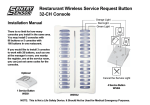
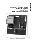
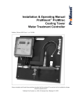
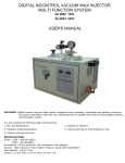
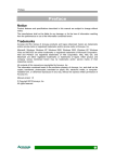
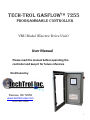
Tech-Trol GasFlow™ 7255
Programmable Controller
VRU Model (Electric Drive Unit)
User Manual
Please read this manual before operating the
controller and keep it for future reference
Distributed by
Pawnee, OK 74058
www.techtrol-usa.com
918 762-1050
1
Table of contents
Introduction . . . . . . . . . . . . . . . . . . 3
Home Screen . . . . . . . . . . . . . . . . . .4
Buttons
Zero suction . . . . . . . . . . . . . . . .5
Display sensor data . . . . . . . . . .6
Set system parameters . . . . . . .7
Set points . . . . . . . . . . . . . . . . . .8
Press to start . . . . . . . . . . . . . . .9
Run / Shutdown mode
Run mode . . . . . . . . . . . . . . . . . . 10
Shutdown mode . . . . . . . . . . . . .10
‘Set system parameters’ screen
Suction delay . . . . . . . . . . . . . . . 11
Suction relay . . . . . . . . . . . . . . . . 11
Run hours . . . . . . . . . . . . . . . . . . 12
Lock out timer . . . . . . . . . . . . . . 12
Motor range . . . . . . . . . . . . . . . 12
Ball valve open close . . . . . . . . . 12
Throttling motorized valve . . . . . . 13
Touch screen calibration . . . . . . . . 17
2
Introduction
The TechTrol GasFlowTM programmable controller will continuously
monitor and control critical conditions on gas compressors. The 7255
model is specific to the electric drive units.
Features of the controller include a high-resolution graphics “Touch”
screen, menu driven user selectable commands and a variety of control
features selectable by the user to help maintain suction on the Vapory
Recovery Unit.
The various options and how each one works are discussed in this User’s
Manual.
Note : The features described in this manual are for reference only. The
features on the controller are subject to customer specifications.
3
At a Glance
Home Screen
The main screen or the “Home” screen is where the user will always
start to get to any of the settable parameters on the controller. The
Home screen displays the serial number, compressor-company’s name,
web site address and the “RUN HOURS”. Apart from this, the home
screen also contains five buttons at the bottom namely “Press To Start”,
“Set Points”, “Set System Parameters”, “Display Sensor Data” and “Zero
Suction”.
Serial No
Run Hours
Set Points button
Press To Start button
Set System Parameters button
Display Sensor Data button
Zero Suction button
Figure 1 – Home Screen
4
Zero Suction button
This button will allow the user to zero the current value of the suction
sensor. The user should check the following a) Suction sensor is properly
connected to the controller b) There is no Pressure on the sensor
Note : Sensor must be at atmospheric pressure before Zero Suction button
is pressed.
Note 1 : The suction sensor must be
connected during the zero mode. Do
not zero the suction sensor while it is
disconnected from the controller. This
will result in false suction sensor
readings.
Note 2 : For application where the
suction is read in inches water
column or ounces, the suction
sensors must be calibrated every 30
days.
Figure 2 – Press to zero
Once the Zero Suction button is chosen from the Home Page, the above
screen appears. The Press To Zero button has to be selected in order to
complete the operation. No changes will be made until then.
If you do not want to continue, select the Home Page button to go back to
the Home Page. The sensor input will not have changed.
5
Display Sensor Data button
This button will display the real time sensor values. It can be viewed even
when the compressor is not running. The Home Page button can be
pressed to go to the Home Page. The sensor data display screen is
automatically displayed after start sequence is followed and completed.
Figure 3 – Display Screen Data
6
Set System Parameters button
This button lets the operator specify how the compressor will operate by
how the system parameters are set. The Set System Parameters screen is
shown in Fig 4– Set System Parameters. The
buttons are used to
scroll up and down between the different parameters. The
button is
used to navigate left/right within the same parameter and the
buttons enable user to raise or lower the selected parameter’s value. The
2nd, 3rd and 4th columns represent the upper range, lower range and their
units respectively. The different parameters like suction delay, suction
range, etc are explained on page 13.
Note : Pressing this button during normal running conditions will kill
the motor.
Figure 4 – Set System Parameters
7
Set Points button
The set points are also called the kill points. They represent the upper and
lower limits of each parameter for which the system needs to be stopped.
They can be set for all analog sensors. The
buttons are used to
scroll up and down between the different parameters. The
button is
used to navigate left/right within the same parameter and the
buttons enable the user to raise or lower the selected sensor’s value. The
2nd, 3rd and 4th columns represent the upper range, lower range and
their units respectively.
Note : Pressing this button during normal running conditions will kill
the motor.
Figure 5 – Set Points
8
Press To Start button
Once the Press To Start button is pressed, there will be a 10 second
countdown, indicating that the system is about to start. This is
accompanied by a flashing amber light (shown in figure 6a). Once the
system starts, the display screen figure 3 (on page 6) will be displayed.
If the Emergency Stop button (Figure 6b) is pressed, the screen will
show the display as in Figure 7.
Note : Pull out the emergency start button and then press start button
to start.
Flash light
Figure 6a – Flash Light
Emergency stop
button
Figure 6b – Emergency stop button
Figure 7 – Press to start
9
The Run and Shutdown mode
Run/Shutdown Mode
Run Mode : Once the compressor starts, the unit is considered to be in
‘Run mode’. The Display Data screen (figure 3) will show current values of
all the sensors. While the compressor runs, the controller will monitor all
sensor values
Shutdown Mode : If the controller
shuts down for any reason other than
high or low suction, user must resolve
the fault is listed on the screen before
restarting the compressor. If the
controller has the Auto-Start feature
enabled, it will restart automatically
once the suction corrects itself.
General controller shutdown
criteria examples
•High / Low suction
• High / Low discharge
• Excessive vibration
• RPM
• High / Low compressor oil
pressure
• High / Low engine oil pressure
• Low engine oil level
• High Engine Temperature
• High compressor temperature
Note : If auto-start feature
is disabled, the controller
will not restart
automatically.
Figure 8 - Shutdown
10
‘Set system parameters’ screen
“SUCTION DELAY” – Allows the user to select how quickly the controller
will react to Suction Pressure in order to delay a shutdown. It works kind
of like a de-bounce for rapidly changing Suction Pressures. The Suction
Delay can be set for up to 120 seconds or down to zero. The system
continually polls all sensor inputs while the compressor is running. If
Suction Pressure is beyond one of the set limits longer than the delay
period, the Compressor will shut down with a Suction fault and be
displayed on the Shut Down Screen. For all other Sensor Inputs that are
outside of the Set Points, the Compressor will shut down immediately.
The value in the left column (H-SP) is the only value that needs to set for
Suction Delay. The right column (L-SP) has no effect.
“SUCTION RELAY” - This feature allows the user to set the desired
pressure range that will activate the “bypass” ball valve and Motor
Speed. The left column (H-SP) is the high pressure side in which the
bypass valve will close and go to the “sale gas” mode when the Suction
Pressure exceeds this value. If Suction drops below this value, the
bypass valve will open and go into bypass mode in an effort to recirculate gas within the compressor. The right column (L-SP) is the low
pressure side.
If a throttling ball valve is connected to the bypass line, it will attempt to
adjust to the upper setting. It gives more control over the bypass mode.
11
‘Set system parameters’ screen (Continued)
“RUN HOURS” - Unit Run Hours – For maintenance purposes the run
hours can be reset with every oil and/or filter change. If a cumulative
run time is kept, and the unit receives a program upgrade you can
reset the run hours to the value on the unit at the time of the
upgrade.
“LOCK OUT TIMER” – The user can set this variable for the start-up
lockout timer. On startup, the sensors will not be monitored for a
fault condition until this timer counts down to zero.
Caution: Do not set this parameter such that you run the machine
long enough to cause damage. It is the operator's responsibility to
monitor sensor data and use the “Emergency Shut-Down” switch if
necessary during the lock-out mode.
“MOTOR RANGE” - The user can set the maximum and minimum RPM
of the motor. If “VAR FREQUENCY” is enabled, the motor will run
proportional to the suction as listed above. If “VAR FREQUENCY” is not
enabled “0‟, the motor will run at the high set value only.
“BALL VALVE OPEN/CLOSE” – The bypass throttling ball valve can be
programmed to operate at a relative speed from “1” to “20” The open
and close function can be set independently. A setting of “1” will move
the ball valve the slowest and a setting of “20” will cause the maximum
speed at which the ball valve will operate. The user should experiment
with these settings to optimize the control. For example, a slower
moving ball valve may allow excess pressure into the bypass.
12
Throttling Motorized Ball Valve
The throttling ball valve is used for bypass and for other applications when
required.
The ball valve is controlled by the panel while set in “Auto” mode. The
black knob located on the front of the ball valve allows the user to select
between “Auto” and “Manual”. Manual mode allows operator to use the
handle on top to manually open or close the ball valve. Note the handle
direction represents the position of the opening of the ball valve. Do not
try to manually adjust the ball valve position when in the “Auto” mode.
From time to time, it may be necessary to calibrate the ball valve. If the
ball valve, does not go to the “fully closed” position or to the “fully open”
position as expected. To complete a calibration of the ball valve, proceed
as follows:
This procedure will externally mechanically reset the open and closed
position for electric actuators with the DPS module installed when the
units gets moved off zero.
Figure 10 – Motorized Ball Valve
13
1. Remove the power supply to the actuator. (Remove connector or turn
power off) the power connector is the large gray one on the far left side.
Remember to check if the LED light on the top of the actuator is off.
Figure 11 – Removing connector
Figure 12 – LED light off
2. Remove the small black center connector from the actuator.
Note : The connector pins are oriented
in only one way and can be connected
only to the respective slots
Figure 13 – Small connector removed
3. Place the ball valve in Manual Mode.
4. Adjust the ball valve to the closed position, perpendicular with the handle
on top.
Figure 14 – Normally closed position
14
5. Turn the ball valve to Auto Mode. Now remove the gasket for the pin.
6. On the small black plug “on the actuator”, center connector, short pin 3
to Earth Ground pin.
Pin3
Ground
Figure 15 – connecting pin3 and ground
Figure 16 – LED light goes solid
7. Turn the power back on to the actuator and wait until the LED light on
the top of the actuator goes solid.
Gasket
Figure 18 – Position reset
Figure 17 - Gasket
8. The actuator will then go through a mechanical position reset.
9. When the reset is complete (closed to open and back to closed) then
turn the power back off.
10. Put the gasket back in place and re-connect small black center
connector and turn power back on to test the actuator.
15
11. Screw the connectors back in.
Note :If the LED light is blinking, it
means that the actuator is not
working.
Figure 19 – Connectors back in place
16
Touch Screen Calibration
Sometimes if something is selected on the touch screen, it may not get
selected. This type of problem arises for all devices with touch screen.
This means that the touch screen is out of calibration. Now the touch
screen needs to be calibrated. Below listed are the steps that are
needed to calibrate the touch screen.
1. Open the controller door and make a quick reset of the screen
power by switching off and turning back on the switch shown in the
picture, with the index finger on the screen.
On – off button
Figure 20 – On-off button
Figure 21 – Holding the screen when it is switched off
2. Hold the screen while it is off. Switch the screen on. The caliubration
screen appears. Do not hold the screen for too long now. When the
calibration screen comes up, tap the screen immediately so that it
takes to the calibration screen shown. If it doesn’t, repeat the above
process until you get to the calibration screen.
Figure 22 – Screen turns back on
Figure 23 – Tap when prompted to 17
3. Tap the screen again in order to calibrate the screen.
Figure 24 – Blinking dot at top left
Figure 25 – Tap the blinking dot
4. A blinking dot appears on the top left of the screen as shown. Touch
that and now the blinking dot appears in the bottom right of the screen
which has to be touched. Now the touch screen calibration is done.
Figure 26 - Blinking dot at bottom right
Figure 27 – Tap the blinking dot
18
19
20