1
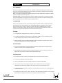
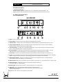
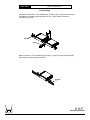
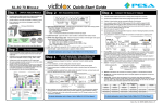
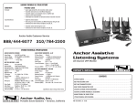
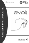
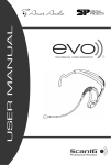
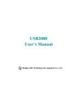
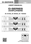
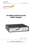
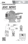
ANY SPOT
SPOT
®
SERIES
WIRELESS
MICROPHONE
SYSTEMS
AS-M500 AND AS-M700 SERIES
UHF
BAND
GA LAX Y AU D I O
MAKERS OF THE ORIGINAL HOT SPOT PERSONAL MONITOR
ANY SPOT WIRELESS MICROPHONE SYSTEMS
1. Introduction ………………………………………….……….……….…… 1
2. Safety ………………………………………………………………………… 1
3. Environment ………………………………………………………………... 1
4. Wireless Note……………………………………………….……………... 1
5. Product Description ………………………………..………….………..… 2
5.1 Diversity Type Receiver
5.2 Handheld Microphone
5.3 Bodypack Transmitter
6. Basic Connections……………….…………………..……….…..……..… 10
7. Setting Up ………………………………………………….………...……
12
7.1 Connecting the receiver to power
7.2 Connecting the receiver to an audio mixer or an amplifier
7.3 Inserting batteries into the handheld / bodypack transmitter
7.4 Setting up the handheld transmitter
7.5 Setting up the bodypack transmitter
8. Trouble-shooting ……………………………………..………….…….…. 14
9. System Features and Specifications………….…………………...
15
ANY SPOT
WIRELESS NOTE
FCC Statement
This device complies with part 15 of the FCC rules. Operation is subject to the following two conditions: (1)This
device may not cause harmful interference and (2) This device must accept any interference received, including
interference that may cause undesired operation.
Notice : The changes or modifications not expressly approved by the party responsible for compliance could void
the user's authority to operate the equipment.
IMPORTANT NOTE: To comply with the FCC RF exposure compliance requirements, no change to the antenna
or the device is permitted. Any change to the antenna or the device could result in the device exceeding the RF
exposure requirements and void user's authority to operate the device.
1. Introduction
Thank you for purchasing our product. These wireless microphone systems operate on UHF band frequencies
with synthesizer control. Each system with 64 or 700 selectable frequencies, via Phase Locked Loop (PLL)
circuitry, makes it easy to choose non-interfering channels. (The number of available frequency channels
depends on local regulations.) Please read this instruction manual carefully before operating the system. This
manual covers the functions and operations of the wireless microphone systems.
2. Safety
Ø
Do not spill liquid on the appliance and do not drop it on a hard surface.
Ø
Do not place the appliance near heat sources such as radiators, amplifiers, etc. Do not expose it to direct
sunlight, extremely dusty conditions, excessive moisture, or vibration.
Ø
Remove the battery from the transmitter if the appliance will not be used for a long period of time. This will
avoid the damage resulting from a defective leaking battery.
3. Environment
Ø
Do not throw used batteries into a fire or garbage bin with domestic rubbish. Be sure to dispose of used
batteries in accordance with local waste disposal rules.
Ø
When disposing of the equipment, remove the batteries, separate the case, circuit boards, and cables, and
dispose of all components in accordance with local waste disposal rules.
4. Wireless Note
Ø
Before setting up make sure that the transmitter and receiver are tuned to the same frequency.
Ø
Do not use two transmitters on the same frequency.
Ø
Use good quality batteries to avoid the damage resulting from a defective leaking battery.
Ø
Turn the volume control on the receiver to adjust the receiver's output level to match the input level
requirements of the audio mixer, amplifier, or other device to which it is connected. (Refer to 7.2)
Ø
To avoid interference, do not operate the receiver near metal objects and maintain a line of sight between the
transmitter and receiver.
Ø
Avoid placing the receiver near TV’s, radios, computers, or other RF generating equipment such as CD players,
DAT machines, and digital processors that may be capable of producing interference.
UHF
WIRELESS MICROPHONE
1
ANY SPOT
PRODUCT DESCRIPTION
5. Product Description
5.1 Diversity Type Receiver
Stationary diversity receivers are used with all 64 or 700 selectable
channel transmitters. The
receivers operate on UHF band frequencies with PLL synthesizer control and are powered by 12V DC.
AS –M500R 64 Channel, Diversity, 1/2
Rack, Detachable Antenna
AS-M500R
ANY SP O T
GA LAX Y AU D I O
AS-M500R
UHF RECEIVER
VOLUME
GR
POWER
CH
ANY SPOT
RF
1
9
2
10
3
11
AF
MIN
MAX
DC OUT
4
5 6
7
8
12
13
14
9
1. Power: Power on pushbutton switch.
2. Group Selector: Changes receiver Group setting. (for 8 selectable frequency groups)
3. Channel Selector: Changes receiver Channel setting.(for 8 selectable frequency channels within each frequency group)
4. Group & Channel Indicators: Numeric LCD's display the group and channel number on which the system is operating.
These two selections make up the frequency program number.
5.
RF Level Indicators: Five LED's glow to indicate RF signal strength. The more LED's that glow, the stronger the received
signal. If none of these LED's glow, no signal is being received.
6. AF Level Indicator: Five LED's glow to indicate the audio signal strength being received from the transmitter. The more
LED's that glow, the stronger the audio signal. If none of these LED's glow, no audio signal is being received.
7. Level Control: This rotary control adjusts the receiver's output level within the range selected by the mic/line switch. (12)
8. DC Out: Using the supplied charging cable, the DC output supplies charging current to a transmitter equipped with rechargeable
batteries. Charging can take up to 10 hours. During charging the LED of the transmitter flashes constantly.
9. Antenna Input Connector: TNC-type connectors provide connection to the supplied antennas or to coaxial cable used
with an antenna divider, antenna boosters, or remote antennas.
10. Balanced Output: Balanced 3-pin XLR audio output for connecting to an XLR input, e.g., a microphone input on a mixing console.
11. Unbalanced Output: Unbalanced ¼” (6.3mm) mono jack audio output for connecting to
a ¼” (6.3mm) input, e.g., a guitar amplifier.
12. Mic/line Switch: Switches both the XLR and ¼” (6.3mm) outputs to mic or line level ranges.
13. Squelch Adj. : This control helps supress noise to keep it from entering the system.
Setting the squelch too high will reduce the range of the system. Set the squelch to minimum
before turning the receiver on.
14. DC Jack: DC input connector for the supplied AC power adapter.
2
UHF
WIRELESS MICROPHONE
ANY SPOT
PRODUCT DESCRIPTION
AS –M700R 700 Channel, Diversity, 1/2
Rack, Detachable Antenna
AS-M700R
GA LAX Y AU D I O
ANY SP O T
AS-M700R
POWER
HEADPHONE
VOLUME
CHANNEL
MIN
MAX
POWER
VOLUME
CHANNEL
FREQ
VOLUME
CHANNEL
UHF RECEIVER
RF
RF
ANY SPOT UHF RECEIVER
1
3
2
4
5
ANT B
TRUE DIVERSITY
VOL
MHz
7
6
AF
DC OUT
DC OUT
AF
8
9
10
11
ANT A
AUDIO OUTPUT
UNBALANCED
SQUELCH
LINE
DC ONLY
12V 1A
MIC
DC OUT
8V/80mA
DC OUT
8V/80mA
BALANCED
12
13
14
15
16
17
12
1. Headphone Monitor Volume Control: Rotate this knob to control headphone volume level.
2. Headphone Output Connector: Plug headphone into this ¼” (6.3mm) connector to monitor receiver audio.
3. Power: Switches the receiver on and off.
4. Channel Button: Press this button to adjust the channel upward.
5. Channel Button: Press this button to adjust the channel downward.
6. Programmable Display: Displays channel number, frequency, and volume level.
7. RF Level Indicators: Five LED's glow to indicate RF signal strength. The more LED's that glow, the stronger the received
signal. If none of these LED's glow, no signal is being received.
8. AF Level Indicators: Five LED's glow to indicate the audio signal strength being received from the transmitter. Green indicates
normal operation. RED indicates approaching overload condition.
9. Volume Button: Press this button to decrease the receiver output level from within the range selected by the mic/line
switch. (15)
10. Volume Button: Press this button to increase the receiver output level from within the range selected by the mic/line
switch. (15)
11. DC Out: Using the supplied charger cable, the DC output supplies charging current to a transmitter equipped with
rechargeable batteries. Charging can take up to 10 hours. During charging the BATT indicator of the transmitter pulses constantly.
12. Antenna Input Connector: TNC-type connectors provide connection to the supplied antennas or to coaxial cable used
with an antenna divider, antenna boosters, or remote antennas.
13. Balanced Output: 3-pin XLR connector provides balanced mic level or line level output.
14. Unbalanced Output: ¼” (6.3mm) phone jack provides unbalanced mic level or line level output.
15. Mic/Line Switch: Selects the output range of the XLR balanced connector or the ¼” (6.3mm) unbalanced phone jack.
It can be set for microphone (-20dB) or line-level (0dB).
16. Squelch: This control helps suppress noise to keep it from entering the system. The higher the squelch control is set ,
the lower the sensitivity of the receiver and the smaller the service area of the system. Set the squelch to minimum before turning the
receiver on.
17. DC IN: Input connector for the supplied AC power adapter.
UHF
WIRELESS MICROPHONE
3
ANY SPOT
PRODUCT DESCRIPTION
Rack Mounting
Combine two receivers in a 19” standard rack by using 2 short L type metal rack ears
(AS-SRE) and 2 metal connecting plates (AS-CP). (Each system includes an
AS-SRE and a AS-CP.)
AS-SRE
AS-CP
Mount a receiver in a 19” standard rack by using 2 L type long metal racks (AS-LRE).
(each system includes a pair of AS-LRE.)
AS-LRE
4
UHF
WIRELESS MICROPHONE
ANY SPOT
PRODUCT DESCRIPTION
Charging Connection Diagram
To charge rechargeable batteries, connect the supplied charger cable to the receiver and a microphone or belt pak
transmitter. Make sure that the transmitter’s power switch is in the “off” position. The LED on the 500 series
transmitters will flash during charging. The “BATT” indicator on the 700 series transmitters will pulse during charging.
Charging can take up to 10 hours. Never connect more than one transmitter to the charging connection. If more
than one transmitter needs to be recharged at the same time, use the AS-DCC charger kit that can recharge up to
five transmitters simultaneously.
ANY SP O T
VOLUME
POWER
AS-M500R
UHF RECEIVER
OPEN
GA LAX Y AU D I O
GR
CH
ANY SPOT
RF
AF
MIN
MAX
DC OUT
or
UHF
WIRELESS MICROPHONE
5
ANY SPOT
PRODUCT DESCRIPTION
5.2 Handheld Microphone
The handheld microphone operates on UHF band frequencies with PLL synthesized control. 64 (AS-HH5) or 700
(AS-HH7) preprogrammed selectable UHF frequencies are provided to avoid interference. The AS-HH5 is equipped
with a uni-directional dynamic cartridge. The AS-HH7 is equipped with a uni-directional electret condenser cartridge.
Power is supplied by two 1.5V AA size batteries.
AS-HH5
1
2
3
4
7
5
6
8
6
1.
Grille: Protects the microphone cartridge and helps reduce breath sounds and wind noise.
2.
Low Battery LED: LED indicates battery status. Switching the power to "ON” causes the LED to flash once
and then go out indicating that the batteries have sufficient power. If the LED stays on, it indicates that the batteries
have insufficient power and should be changed soon. If the status LED fails to flash, the batteries are either
dead or not positioned correctly, and you should correct the positioning or charge or replace the batteries
3.
On/off Switch: Turns transmitter power on and off.
4.
Battery Compartment: Insert two AA batteries into the compartment and make sure that the polarity of the
batteries is correct.
5.
Group Selector: Changes transmitter group setting. (for 8 selectable frequency groups)
6.
Channel Selector: Changes transmitter channel setting. (for 8 selectable frequency channels within each
frequency group)
7.
Battery Cover: Slide the battery cover down to expose the battery compartment and the Group/Channel selectors.
8.
Charging Input: If rechargeable batteries are used, they can be charged by using the supplied DC-plug
cable to connect the mic's charging input to the DC out on the receiver. Charging can take up to 10 hours.
UHF
WIRELESS MICROPHONE
ANY SPOT
AS-HH7
PRODUCT DESCRIPTION
1
2
3
4
CH
CH
5
6
7
8
10
9
1.
Grille: Protects the microphone capsule and helps reduce breath sounds and wind noise.
2.
Programmable Display: Displays the channel number and battery power level
3.
On/off Switch: Turns the transmitter power on and off.
4.
Channel Button: Press this button to adjust the channel upward.
5.
Channel Button: Press this button to adjust the channel downward.
6.
Battery Lock: locate the arrow and press inward towards the battery and lift the battery lock open
7.
Battery Compartment: Insert two 1.5V AA dry or rechargeable batteries into the compartment and make
sure that the batteries are positioned for correct polarity.
8.
Battery Cover: Unscrew to expose battery compartment and group and channel buttons.
9.
Charging Input: If rechargeable batteries are used, they can be charged by using the supplied DC-plug
cable to connect the mic's charging input to the DC out on the receiver. Charging can take up to 10 hours.
10. Antenna: Permanently connected, helical antenna.
UHF
WIRELESS MICROPHONE
7
ANY SPOT
PRODUCT DESCRIPTION
5.3 Bodypack Transmitter
AS-MBP5
The bodypack transmitter operates on UHF band frequencies with PLL synthesized control. 64 preprogrammed
selectable UHF frequencies are provided to avoid interference. Power is supplied by two 1.5V AA size batteries.
5
1
2
4
3
9
6
10
8
1
2
7
3
6
5
4
1
2
3
5
4
CHANNEL
AA BATTERY
7
6
AA BATTERY
GROUP
8
7
GAIN
8
CHARGING
INPUT
1.
Mini XLR connector: Input connection for a microphone or instrument cable.
2.
On/Off Switch: Turns transmitter power on and off.
3.
Low Battery LED: LED indicates battery status. Switching the power to "ON” causes the LED to flash
once and then go out indicating that the batteries have sufficient power. If the LED stays on, it indicates
that the batteries have insufficient power and should be changed soon. If the status LED fails to flash,
the batteries are either dead or not positioned correctly, and you should correct the positioning or replace
or charge the batteries.
4.
Mic/Line Selector: The switch sets the audio input either to microphone level or line level.
5.
Antenna: Permanently connected, helical antenna.
6.
Group Selector: Changes transmitter group setting. (for 8 selectable frequency groups)
7.
Channel Selector: Changes transmitter channel setting. (for 8 selectable frequency channels within
each frequency group)
8.
Gain: The rotary control adjusts the sensitivity of the transmitter to the level of the connected
lapel/headset microphone or instrument.
9.
Battery Compartment: Insert two 1.5v AA dry or rechargeable batteries into the compartment
and make sure that the batteries are positioned for correct polarity.
10. Charging Input: If rechargeable batteries are used they can be charged by using the supplied DC-plug
cable to connect the charging input to the DC out on the receiver. Charging can take up to 10 hours.
8
UHF
WIRELESS MICROPHONE
ANY SPOT
PRODUCT DESCRIPTION
AS-MBP7
The bodypack transmitter operates on UHF band frequencies with PLL synthesized control. 700 preprogrammed
selectable UHF frequencies are provided to avoid interference. Power is supplied by two1.5V AA size batteries.
2
1
3
4
8
CHARGING
INPUT
5
6
AA BATTERY
10
7
AA BATTERY
9
1.
On/Off Switch: Turns transmitter power on and off.
2.
Mini XLR Connector: Input connection for a microphone or instrument cable.
3.
Antenna: Permanently connected, helical antenna.
4.
Programmable Display: Displays channel number and battery status.
5.
Channel Button: Press this button to adjust the channel upward.
6.
Channel Button: Press this button to adjust the channel downward.
7.
Mic/Line Selector: The switch sets the audio input to either microphone level or line level.
8.
Gain: The rotary control adjusts the sensitivity of the transmitter to the level of the connected
microphone or instrument.
9.
Battery Compartment: Insert two 1.5V AA dry or rechargeable batteries into the compartment
and make sure that the batteries are positioned for correct polarity.
10. Charging Input: : If rechargeable batteries are used they can be charged by using the supplied
DC-plug cable to connect the charging input to the DC out on the receiver. Charging can take up
to 10 hours.
UHF
WIRELESS MICROPHONE
9
ANY SPOT
BASIC CONNECTIONS
6. Basic Connections
Connect the receiver output to the audio mixer or amplifier input, using a standard audio cables with 3-pin XLR
connectors or ¼” (6.3mm) phone plugs. Never use the balanced and unbalanced audio outputs at the same time!
This may cause signal loss or increased noise.
AUDIO MIXER
LOUDSPEAKER
10
AMPLIFIER
LOUDSPEAKER
UHF
WIRELESS MICROPHONE
ANY SPOT
BASIC CONNECTIONS
An antenna booster is highly recommended for long-distance purposes, such as in a stadium or in an auditorium.
By means of the antenna holders, the antennas and booster can be put wherever you want. It is an ideal design for
multi-channel applications. Antenna boosters can be used with receivers that have detachable antennas.
The antenna holder makes it easy to place the antenna wherever it needs to be in relation to the receiver. The holders
can be mounted on mic stands or walls.
TNC female connector for connecting a UHF antenna
TNC female connector for connecting to antenna cable or an
antenna booster.
Screw adapter to screw antenna holder onto a microphone stand.
UHF
WIRELESS MICROPHONE
11
ANY SPOT
SETTING UP
7. Setting Up
NOTICE: Prior to setting up, check that the transmitter and receiver are tuned to the same frequency. Two or
more transmitters operating on the same frequency can not be used at the same time in the same
place, so please select different frequencies which can be used simultaneously in the same place.
7.1 Connecting the receiver to power
Ø
Plug the antennas into the TNC sockets on the receiver and point them upward.
Ø
Check that the voltage of the supplied AC adapter conforms to the voltage (AC110 or 220) available in the
local area. Using the wrong AC adapter may cause irreparable damage to the unit.
Ø
Plug the feeder cable of the supplied AC adapter into the DC IN socket on the receiver. Then plug the AC
adapter into a power outlet.
7.2 Connecting the receiver to an audio mixer or an amplifier
In order to ensure quality sound and avoid distortion, please adjust the volume level according to following
instructions.
Never use the balanced and unbalanced audio outputs at the same time! This may cause
signal loss or increased noise.
Ø
Make sure that the MIC/LINE switch is in the correct position for the type of input to
which you are connecting.
AS-500R
Ø
MAX
MIN
VOLUME
MAX
MIN
VOLUME
When using a standard audio cable with 3-pin XLR connectors or ¼” (6.3mm) phone
Ø
plugs to plug into the MIC IN of an audio mixer or amplifier, please turn the Volume
Level Control on the receiver to the 1 o'clock position. The output level for balanced
and unbalanced outputs is about 77mV.
When using a standard audio cable with 3-pin XLR connectors or ¼” (6.3mm) phone
Ø
plugs to plug into the LINE IN of an audio mixer or amplifier, please turn the Volume
Level Control on the receiver to the MAX position. The output level for balanced and
unbalanced outputs is about 770mV.
AS-700R
Ø
When using a standard audio cable with 3-pin XLR connectors or ¼” (6.3mm) phone
Ø
plugs to plug into the MIC IN of an audio mixer or amplifier please push the Volume
Button on the receiver to a level of approximately 20. The output level for balanced and
unbalanced outputs is about 77mV.
When using a standard audio cable with 3-pin XLR connectors or ¼” (6.3mm) phone
Ø
plugs to plug into the LINE IN of an audio mixer or amplifier, please push the Volume
Button on the receiver to a level of approximately 32. The output level for balanced and
unbalanced output is about 770mV.
12
UHF
WIRELESS MICROPHONE
ANY SPOT
SETTING UP
7.3 Inserting batteries into the handheld microphone / bodypack transmitter
Ø
Open the battery cover and insert batteries into the battery compartment conforming to the polarity (+)(-)
marks. The transmitter can not work with incorrectly inserted batteries.
Ø
AS-MBP5/AS-HH5
Push the ON/OFF switch to “ON” to switch the power on. The LED will flash momentarily. If the batteries have
sufficient power, the LED flashes only once. If the LED stays on, it indicates that the batteries have insufficient
power and should be replaced or charged soon. If the status LED fails to flash, the batteries are either dead or not
positioned correctly, and you should correct the positioning or replace or charge the batteries
Ø
AS-MBP7/AS-HH7
Push the ON/OFF switch to “ON” to switch the power on. A bar graph on the LCD shows the battery power level. Fully
charged batteries will show four bars, while low batteries may show only one bar. If the bar graph displays insufficient
power the batteries should be replaced or charged soon. If the LCD fails to light, the batteries are either dead or not
positioned correctly, and you should correct the positioning or replace or charge the batteries.
Ø
Close the battery cover.
7.4 Setting up the handheld microphone transmitter
Switch ”ON” the transmitter.
Ø
Switch the receiver power on and make sure the frequency selected on the receiver matches the one selected
Ø
on the transmitter.
Ø
Test the microphone and while watching the RF and AF levels on the receiver, adjust the levels on your audio mixer
or amplifier.
7.5 Setting up the bodypack transmitter
A. Connecting a microphone
Plug the mini XLR connector of the microphone cable into the audio input connector on the bodypack
Ø
transmitter.
Switch “ON” the transmitter and receiver. Make sure the frequency selected on the receiver matches the one
Ø
selected on the transmitter.
Open the battery cover. Push the MIC/LINE switch to “MIC” and use the supplied screwdriver to adjust the
Ø
GAIN to an appropriate position. The receiver’s AF level should peak into the red only on the loudest signals.
Ø
Test the microphone and while watching the RF and AF levels on the receiver, adjust the levels on your audio mixer
or amplifier.
B. Connecting an instrument
Plug the ¼” (6.3mm) phone plug of the optional line cable into the output jack on the instrument and the
Ø
mini XLR into the audio input connector on the bodypack transmitter.
Switch “ON” the transmitter and receiver. Make sure the frequency selected on the receiver matches the one
Ø
selected on the transmitter.
Open the battery cover. Push the MIC/LINE switch to “LINE” and use the supplied screwdriver to adjust the
Ø
GAIN to an appropriate position. The receiver’s AF level should peak into the red only on the loudest signals.
Ø
Play the instrument and while watching the RF and AF levels on the receiver, adjust the levels on your audio mixer
or amplifier.
UHF
WIRELESS MICROPHONE
13
ANY SPOT
TROUBLE SHOOTING
8. Trouble-shooting
Problem
Solution
No sound
Ø
Check the power supply of the microphone and receiver.
Ø
Check that the transmitter and receiver are tuned to the same
frequency.
Ø
Check whether the mixer or amp is switched on and the receiver
output is connected to the audio mixer or amplifier input.
Ø
Check whether the transmitter is too far away from the receiver or
if the SQUELCH control is set too high.
Ø
Check whether the receiver is located too near metal objects or if
there are obstructions between the transmitter and the receiver.
Sound interference
Ø
Check the antenna location.
Ø
When using 2 or more microphone sets simultaneously, make
sure that the chosen frequencies are not interfering with each
other
Ø
Check whether the interference comes from other wireless
microphones, TV’s, radios, etc.
Distortion
Ø
Check the gain control on the bodypack transmitter to make sure
it is not set too high or too low.
Ø
Check whether the interference comes from other wireless
microphones, TV’s, radios, etc.
14
UHF
WIRELESS MICROPHONE
ANY SPOT
FEATURES & SPECIFICATIONS
9. System Features
Ø
The flexibility and the professional performance of these wireless systems are specifically designed for stages,
places of worship, and professional sound installations.
Ø
The wireless microphone system with 64 (ASM-500) or 700 (ASM-700) selectable frequencies via Phase Locked
Loop (PLL) circuitry makes it easy to choose non-interfering channels.
Ø
System offers super high sensitivity and extremely low noise transmission and reception.
Ø
SMT assembled PCB module ensures the quality and stability.
10. System Specification
AS-M500R Receiver
Ø
Carrier Frequency Range
: UHF band 682~698 MHz
Ø
Oscillator
: PLL synthesized, 64-selectable channels
Ø
Frequency Stability
:±
0.005%
Ø
S/N ratio
: >94dB, at 48KHz deviation and 60dBµ
V antenna input
Ø
Image and Spurious Rejection : 80 dB minimum
Ø
Receiving Sensitivity
: 8 dBµV.
Ø
Selectivity
: >50dB
Ø
AF Response
: 50Hz to 15KHz (±
3dB)
Ø
T.H.D.
: <1% (at 1KHz)
Ø
Modulation Mode
: FM
Ø
IF Frequency
: 1st: 56MHz; 2nd: 10.7MHz
Ø
Dynamic Range
: >96dB
Ø
Tone Signal
: 32.768KHz
Ø
Audio Output
: Unbalanced or/and balanced audio outputs
Ø
Power Supply
: 12V DC
Handheld (MS-HH5)/Bodypack Transmitter (AS-MBP5)
Ø
Carrier Frequency Range
Ø
RF Power Output
Ø
Oscillator
Ø
Frequency Stability
Ø
Maximum Deviation
Ø
Spurious Emission
Ø
T.H.D.
Ø
Microphone Cartridge
: UHF band 682~698MHz
: 10mW (max.)
: PLL synthesized, 64-selectable channels
:±
0.005%
:±
48KHz
: >60dB below carrier frequency
: <1% (at 1KHz)
: Handheld: uni-directional dynamic
Lavalier: uni-directional electret condenser
Headset: omni-directional electret condenser
UHF
Ø
Tone Key
: 32.768KHz
Ø
Operating voltage
: DC1.5V x 2 AA size dry or rechargeable batteries
Ø
Current consumption
: 65mA ±
5mA
WIRELESS MICROPHONE
15
ANY SPOT
FEATURES & SPECIFICATIONS
MS-700R Receiver
Ø
Carrier Frequency Range
Ø
Oscillator
Ø
Modulation
Ø
Frequency Stability
Ø
S/N ratio
Ø
Maximum Deviation
Ø
Image and Spurious Rejection
Ø
Receiving Sensitivity
Ø
Selectivity
Ø
AF Response
Ø
T.H.D.
Ø
IF Frequency
Ø
Dynamic Range
Ø
Tone Signal
Ø
Audio Output
Ø
Power Supply
Ø
Current Consumption
: UHF band 630~660MHz
: PLL synthesized
: FM
:±
0.005%
: >94dB, at 48KHz deviation and 60dBµV antenna input
:±
48KHz
: 80 dB minimum
: 6 dB µV.
: >dB
: 50Hz to 15KHz (±
3dB)
: < (at 1KHz)
: 1st: 56MHz 2nd:10.7MHz
: >dB
: 32.768MHz
: Balanced and unbalanced audio outputs
: 12V DC
: Single Channel: About 300mA
Handheld (AS-HH7)/Bodypack Transmitter (AS-MBP7)
Ø
Carrier Frequency Range
: UHF band 630~660MHz
Ø
RF Power Output
: 10mW (max.)
Ø
Oscillator
: PLL synthesized, 700 channels
Ø
Frequency Stability
:±
0.005%
Ø
Maximum Deviation
:±
48KHz
Ø
Spurious Emission
: >60dB below carrier frequency
Ø
T.H.D.
Ø
Microphone Cartridge
: <1% (at 1KHz)
: Handheld: uni-directional electret condenser
Lavalier: uni-directional electret condenser
Headset: omni-directional electret condenser
Ø
Operating voltage
: DC1.5V x 2 AA size dry or rechargeable batteries
Ø
Current consumption
: 70mA ±
5mA
Frequency charts can be found at www.galaxyaudio.com
http://www.galaxyaudio.com/ANYSPOT.html
http://www.galaxyaudio.com/AScharts.html
DESIGN AND SPECIFICATIONS SUBJECT TO CHANGE WITHOUT NOTICE.
16
UHF
WIRELESS MICROPHONE
ANY SPOT
ACCESSORIES
ANY SPOT CASE FOR MICS
AS-CASEMIC
Holds 1 rack mount receiver, body pack transmitter or handheld
microphone, and accessories.
DC CHARGER
AS-DCC
(X) 5
DC charger will charge up to 5 AS-1000R or other
DC chargeable units from Galaxy including
AS-MBP5, AS-MBP7, AS-HH5, & AS-HH7
5 charging cables included.
LONG RACK EARS
AS-LRE
long rack ears will mount any single Any Spot rack unit into
one rack space
SHORT RACK EARS
AS-SRE
short rack ears will mount and two Any Spot rack units into two
rack space; connecting plate included.
HEADSET/LAV COMBO OMNI MIC
AS-HLC
Omni directional, Will work as a headset or lav, Mini XLR
connector.
UNI HEADSET MIC W/ MINI XLR
AS-HS
omni directional heaset (dual ear) can also be used as a
lapel microphone, mini XLR plug, works with both
AS-MBP5 & AS-MBP7
UNI LAV/LAPEL MIC W/ MINI XLR
AS-LV
uni directional lav/lapel microphone, mini XLR plug, works
with both AS-MBP5 & AS-MBP7
GUITAR CABLE 1/4" TO MINI XLR
AS-GTR
UHF
WIRELESS MICROPHONE
guitar/instrument cable, mini XLR plug, works with both
AS-MBP5 & AS-MBP7
17
ANY SPOT
18
NOTES
UHF
WIRELESS MICROPHONE
ONE YEAR LIMITED WARRANTY
This warranty gives you specific legal rights, and you may also have other rights which may vary
from state to state. This warranty is extended to the purchaser and to any purchaser from him/her
for value.
GALAXY AUDIO warrants the materials and workmanship of its products for a period of one
year from the date of the original purchase.
The following are not covered by the warranty:
1. Damage to or deterioration of the exterior cabinet which occurs after delivery.
2. Damage after initial delivery resulting from accident, misuse or neglect.
3. Damage resulting from failure to follow instructions contained in the owner’s manual.
4. Damage resulting from the performance of repairs by someone other than GALAXY AUDIO.
5. Damage occurring during the shipment or delivery of any GALAXY AUDIO product to
GALAXY AUDIO after initial delivery of the product to you.
6. Damage to any GALAXY AUDIO product which has been altered, or on which the serial
number has been effaced or removed.
If your unit requires service, it must be returned, shipping charges prepaid to GALAXY AUDIO
in the United States. (This warranty is not enforceable outside the U.S.) Please call or write
GALAXY AUDIO, 601 E. Pawnee, Wichita, Kansas 67211, (316) 263-2852. We will then issue
you to an RMA# (Return Merchandise Authorization) which will need to be applied to the returned
item. Under no circumstances should you return your unit to the factory without receiving an RMA
or written instruction to do so. If service is required, you must present the original or a copy of the
bill of sale as a proof of date of purchase of your unit. Upon receipt of your unit for service,
GALAXY AUDIO will repair or replace your unit as soon as possible, but in no event later than
30 days after the receipt of the unit. We will return the unit to you, shipping charges prepaid,
provided the necessary repairs are covered by this warranty.
IMPLIED WARRANTIES OF MERCHANT ABILITY AND FITNESS FOR
PARTICULAR PURPOSE ARE LIMITED IN DURATION TO THE LENGTH OF THIS
WARRANTY, UNLESS OTHERWISE PROVIDED FOR BY STATE LAW. GALAXY
AUDIO’S LIABILITY IS LIMITED TO THE REPAIR OR REPLACEMENT, AT OUR OPTION,
OF ANY DEFECTIVE PRODUCT, AND SHALL IN NO EVENT INCLUDE INCIDENTAL OR
CONSEQUENTIAL DAMAGES OF ANY KIND. SOME STATES DO NOT ALLOW
LIMITATIONS ON HOW LONG AN IMPLIED WARRANTY LASTS AND/OR DO NOT
ALLOW THE EXCLUSION OR LIMITATION OF INCIDENTAL OR CONSEQUENTIAL
DAMAGES, SO THE ABOVE LIMITATIONS AND EXCLUSIONS MAY NOT APPLY TO
YOU.
GALAXY AUDIO does not authorize any third party, including any dealer or Authorized Service
Center, to assume any liability on behalf of GALAXY AUDIO or to make any warranty for
GALAXY AUDIO.
UHF
WIRELESS MICROPHONE
19
ANY SPOT
SPOT
®
SERIES
WIRELESS MICROPHONE SYSTEM
UHF
BAND
AS-M500 AND AS-M700 SERIES
GA LAX Y AU D I O
MAKERS OF THE ORIGINAL HOT SPOT PERSONAL MONITOR
601 E. Pawnee Wichita, KS 67211
316.263.2852 FAX 316.263.0642
www.galaxyaudio.com