1
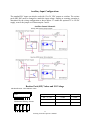
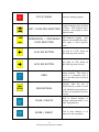
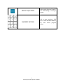
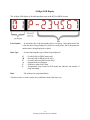
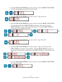
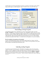
Operator Manual
Rev 20140113
Patent Pending
Copyright © 2009 CENTROID
159 Gates Road, Howard PA 16841 USA
1
Indexing Controller Operator’s Manual
Table of Contents
Chapter 1 - Introduction .............................................................................................................. - 5 Interface .................................................................................................................................. - 5 General Specifications ............................................................................................................ - 6 DX1 I/O Expansion Option .................................................................................................... - 6 Electronic Gear Box EGB Option........................................................................................... - 6 Chapter 2 - Setup ........................................................................................................................ - 7 DC System Connections ......................................................................................................... - 7 AC System Connections ......................................................................................................... - 8 AC/DC Common Connections ............................................................................................... - 9 Standard PLC I/O .................................................................................................................. - 10 Auxiliary Input Configurations ............................................................................................. - 11 Auxiliary Inputs Schematic............................................................................................... - 11 Resistor Pack (SIP) Values and I/O Voltage ........................................................................ - 11 Chapter 3 - Operator Panel ....................................................................................................... - 13 Front Panel Display............................................................................................................... - 13 Function ................................................................................................................................ - 13 10-Digit LED Display ........................................................................................................... - 16 Chapter 4 - General Operation .................................................................................................. - 17 Modes of Operation .............................................................................................................. - 17 Power Up .............................................................................................................................. - 17 Homing ................................................................................................................................. - 17 Setting Part Zero Position ..................................................................................................... - 19 Starting, Stopping, and Selecting Programs ......................................................................... - 19 Chapter 5 - Programming.......................................................................................................... - 21 Introduction ........................................................................................................................... - 21 Program Structure ................................................................................................................. - 21 Program Navigation .............................................................................................................. - 21 Program Editing .................................................................................................................... - 22 Inserting program lines ..................................................................................................... - 22 Deleting program lines ...................................................................................................... - 22 Entering M & G Codes ..................................................................................................... - 22 M & G Codes ........................................................................................................................ - 23 Program Examples and Tutorial ........................................................................................... - 25 Demo Program 1 ............................................................................................................... - 25 Program 1 G-Code ............................................................................................................ - 26 Demo Program 2 ............................................................................................................... - 27 Program 2 G-Code ............................................................................................................ - 30 Chapter 6 - Communications .................................................................................................... - 31 Introduction ........................................................................................................................... - 31 Setting up Hyper Terminal.................................................................................................... - 32 Downloading (receiving) Programs ...................................................................................... - 33 How line numbers for programs are determined .............................................................. - 33 Uploading (sending) Programs ............................................................................................. - 33 Errors..................................................................................................................................... - 34 2
Indexing Controller Operator’s Manual
Remote Operation ................................................................................................................. - 34 Chapter 7 - Machine Parameters and Configuration................................................................. - 37 How to Access ...................................................................................................................... - 37 Chapter 8 - Error Messages....................................................................................................... - 49 Errors..................................................................................................................................... - 49 -
3
Indexing Controller Operator’s Manual
4
Indexing Controller Operator’s Manual
Chapter 1 - Introduction
Interface
The DX1 can be used with any machine as a rotary axis or linear axis. You can interface with the
DX1 by using the input/output cable or RS-232 port methods:
a.) Control by Input/Output Cable:
The DX1 can be used as a partial 4th axis if hooked up using the input/output cable to
a machine that is able to close a relay. This is mostly done using a custom M code.
Once the relay is closed the DX1 will receive the signal to start. All indexing
commands are stored on the DX1. After the command is finished, the DX1 will send a 250ms
pulsed signal to the machine that it is finished.
b.) Control by RS-232 Port:
The DX1 can be interfaced using the RS-232 port where G and M codes can be sent to the
DX1 from a PC. Other information can be sent to the DX1 like programs or updates.
The PC can also gather information from the DX1. You can get the position of the
motor and tell if it is moving or not. Other information can be sent to the PC like
programs or configurations.
Note: CENTROID’s multi-axis controls should be specified where direct control of simultaneous
interpolated moves is required.
5
Indexing Controller Operator’s Manual
General Specifications
Input Voltage
Input Power Rating
Inrush Current
Cooling System
100-130VAC or 200-240VAC @50/60Hz Single Phase
15A
25A
Internal Cooling Fan
Brushed DC
Brushed LV* DC
Brushless AC
110VDC
48VDC
220 or 110 VAC
12A
12A
12A
22A
22A
22A
Over Current, Motor Wiring Fault, Over Load, Over Temp,
Encoder Error, Position Error, Communications Error
Output Motor Voltage
Constant Motor Current
Peak Motor Current
Circuit Protection and
Fault Detection
Clamp Solenoid Power
Standard Inputs
Standard Outputs
Serial Port
Encoder Input
110 VAC , 0.5 A max
3 Inputs (Cycle Start, Clamp Ack, Home)
2 Outputs (Cycle Finish, Clamp)
RS-232, 1 Port, No Flow Control
1 Input, 5v Differential 2 Channel Quadrature with
Commutation, EIA RS-422
Internal Brake Resistor (optional)
Interrupt on 1A Ground Current
0 to 50˚C
-20 to 65˚C
28 lbs
13 ¾” L x 14 ⅛” W x 6 ⅜” H
Dynamic Brake
Motor Wiring Fault
Operating Temperature
Storage Temperature
Weight
Dimensions
*Low Voltage
DX1 I/O Expansion Option
General Purpose Inputs
General Purpose Outputs
3 Inputs Opto Isolated
2 Outputs, Open Collector
Electronic Gear Box EGB Option
Aux Encoder Inputs
A,B,Index (differential)
6
Indexing Controller Operator’s Manual
Chapter 2 - Setup
DC System Connections
DX1 DC Back Panel Connections
MOTOR ENCODER
AND POWER
Note: For each motor configuration the
connector is rotated on the back panel so
the key is in the upright position.
PIN
FUNCTION
A
B
C
D
E
F
G
H
I
J
K
L
M
N
P
R
S
T
U
CLAMP OUTPUT (OUT39)
CLAMP OUT COMMON
+5V OUTPUT (ENCODER)
+5V COMMON
A
/A
B
/B
Z
MOTOR SHIELD
- MOTOR VOLTAGE
+ MOTOR VOLTAGE
NC
HOME INPUT (INP40)
/Z
EXTERNAL SUPPLY COMMON
EXTERNAL SUPPLY
CLAMP ACK INPUT (INP37)
SHIELD
7
Indexing Controller Operator’s Manual
AC System Connections
MOTOR POWER
PIN
A
B
C
D
E
F
G
FUNCTION
PHSA
PHSB
PHSC
SHIELD
CLAMP ACK (INP37)
CLAMP OUT
CLAMP COM
MOTOR ENCODER
PIN
A
B
C
D
E
F
G
H
J
K
L
M
N
P
R
S
T
8
Indexing Controller Operator’s Manual
FUNCTION
B
W
/B
/W
A
/A
Z
/Z
+5V COMMON
/U
V
U
+5V OUTPUT TO ENCODER
/V
I/O COMMON
HOME INPUT (INP40)
SHIELD
AC/DC Common Connections
INPUTS / OUTPUTS
PIN
1
2
3
4
5
6
7
8
FUNCTION
CYCLE START INPUT (INP38)
EXTERNAL SUPPLY
CYCLE FINISH OUT (OUT38)
CYCLE FINISH COM
NO CONNECTION
EXTERNAL SUPPLY COMMON
NO CONNECTION
NO CONNECTION
RS-232
PIN
NAME
DESCRIPTION
1
2
3
4
5
6
7
8
9
N/C
TD
RD
N/C
SG
DSR
N/C
N/C
N/C
NO CONNECTION
TRANSMIT DATA
RECEIVE DATA
NO CONNECTION
SIGNAL GROUND
DATA SET READY
NO CONNECTION
NO CONNECTION
NO CONNECTION
9
Indexing Controller Operator’s Manual
Standard PLC I/O
The DX1 includes 3 isolated inputs (Cycle Start, Home Switch, and Clamp Acknowledge) and 2
fused relay outputs (Cycle Finished, Clamp). The fused power relays are provided for the Rotary
Clamp and Cycle Finished signals. The standard I/O configuration requires a sinking device at 5
Volts. If an alternate supply is used the inputs can accept a sinking or sourcing device at 12, or
24 Volts.
10
Indexing Controller Operator’s Manual
Auxiliary Input Configurations
The standard PLC inputs can also be used with 12 or 24 VDC sensors or switches. The resistor
pack (SIP) R85 must be changed to match the input voltage. Sinking or sourcing operation is
determined by the wiring configuration as shown below. To enable the optional 12 or 24VDC
supply, remove the jumper on J4 between pins 5 and 6.
Auxiliary Inputs Schematic
Resistor Pack (SIP) Values and I/O Voltage
SIP Identification - XXX Indicates Value
4308R-102
-XXX
SIP Internal Wiring / Pinout
SIP Part Number
SIP Resistor Value I/O Voltage
8X – 2 – 471
470Ω
5VDC
4308R – 102 – 102
1.2kΩ
12VDC
4308R – 102 – 222
11
Indexing Controller Operator’s Manual
2.2kΩ
24VDC
12
Indexing Controller Operator’s Manual
Chapter 3 - Operator Panel
Front Panel Display
Key
Function
Description
MODE
Used to cycle through Run,
Program, Configuration, and
Serial communication modes.
FIELD SCAN
Program navigation.
Cycles
through fields on a program line.
In Run mode, cycles through
display options.
LINE SCAN UP
Program navigation. Moves to
previous line in program.
LINE SCAN DOWN
Program navigation. Moves to
next line in program. Repeats if
held down.
CYCLE START
Start a program or continues to
the next line in a program when
in Run Mode. The controller will
remain running a job, unless an
error occurs or E-Stop or Cycle
Cancel is pressed.
13
Indexing Controller Operator’s Manual
CYCLE CANAEL
Cancels a running program.
Toggles between slow and fast
jog rates. LED indicates Slow
FAST / SLOW JOG SELECTION jog mode. Press again to select
opposite mode.
INCREMENTALa/aCONTINUOU
S JOG SELECTION
Toggles between incremental
and continuous jogging. LED
indicates Incremental jog mode.
Press again to select opposite
mode.
AXIS JOG BUTTON
Jogs left (or CCW) based on
speed and jog mode selected.
AXIS JOG BUTTON
Jogs right (or CW) based on
speed and jog mode selected.
ZERO
ZERO RETURN
Sets the Part Zero position to the
current location. This value is
stored in a parameter and is
saved even after power has been
removed.
Used to set Machine home at
powerup. After the axis is
homed, this key is used to return
to the Machine home position or
the Part zero position if one has
been set.
CLEAR / DELETE
Used to discard changes or
interrupt communications, or to
delete a program line.
ENTER / INSERT
Used to enter changes, or to
insert a line into a program.
14
Indexing Controller Operator’s Manual
SELECT M/G CODE
Used to toggle between M and G
codes when editing or creating a
program.
NUMERIC KEYPAD
Used to enter positions, feed
rates, G-codes and other numeric
data. Also selects program
number.
15
Indexing Controller Operator’s Manual
10-Digit LED Display
The 10-digit LED display is divided into three areas in the RUN or PROG modes.
Line Number
- In run mode, this is the line number that is executing. In program mode, this
is the line that is being displayed or edited. In config mode, this is the parameter
number that is being displayed or edited.
Data Type
- A letter indicating the type of data being displayed*
G
M
P
A
F
L
Data
– G-code Field (in PROG mode only).
– M-code Field (in PROG mode only).
– Current Position (in RUN mode only)
– Programmed Axis Position
– Feedrate or other field 3 data.
– Programmed Loop Count. In RUN mode this indicates the number of
loops remaining.
- The indicated or programmed data.
*In other modes, or under certain error conditions, these fields may vary.
16
Indexing Controller Operator’s Manual
Chapter 4 - General Operation
Modes of Operation
RUN
PROG N
CONFIG
SERIAL
The MODE button on the front panel is used to cycle through the modes of operation shown
above. The MODE key is disabled when running a program or during a serial upload or
download. After power up, the control is in RUN mode by default.
RUN mode is used to run a program, jog, home, or set zero. If a program is being executed, the
line number section of the display will indicate the line number. While in run mode, the LED
display will be steady. If a program is not being executed, the line number section of the display
will be blank.
PROG mode is used to select a program, display a program, or edit a program. While in PROG
mode, the line number section will blink. See Chapter 5 for more information.
CONFIG mode is used to display and edit control parameters.
information.
See Chapter 7 for more
SERIAL mode is used to upload/download programs, update firmware, and to enter remote
serial mode. See Chapter 6 for more information.
Power Up
Press the on-off rocker switch to the “ON” position to turn the control on. The LEDs will briefly
display “CENTROID”. If there are errors encountered during the initialization process, they will
be displayed. See Chapter 7 for more detailed information.
After successful initialization with the E-stop released, the display will indicate that the home
position has not been set, by flashing “NOT HOMED” as indicated below.
Homing
After power up of the control, home is set by pressing the ZERO RETURN key*. The display
will show the following message:
17
Indexing Controller Operator’s Manual
After homing, the display will indicate the current position, which will be 0.0 unless the part zero
position has been set.
Home can be set using one of the following three methods:
Home Switch - This method of homing uses a normally closed switch in conjunction with the
index pulse from the encoder. The axis will move at the slow-jog rate until it reaches the home
switch**. It will then reverse direction until the encoder index pulse is located.
Reference Mark - This method of homing uses the manual jog controls to position the axis at a
predetermined location before the homing sequence is initiated. The axis moves at the slow-jog
rate until the encoder index pulse is detected**. A typical reference mark is shown below.
Jog - This method of homing sets the home position to wherever the current position of the axis
is. The axis position is established by manually jogging to the desired location. The encoder
index pulse is not used with this homing method and is therefore not an easily repeatable homing
method.
*If parameter 7 is set to 1.0, the control will automatically start the homing procedure after
initialization. The automatic homing will only work if the control is powered up with the E-stop
released and there are no errors during initialization.
**The direction in which the axis moves to find the home position is determined by parameter 9.
The Slow-Jog rate is determined by parameter 18.
18
Indexing Controller Operator’s Manual
Setting Part Zero Position
Zero is initially set at the home position. To manually set the Part Zero position, jog the axis to
the desired position and then press and hold the ZERO SET key for 3 seconds. This will cause
the position display to read 0.0000 and the machine parameters will store the offset from the
home position. Once part zero has been set, the ZERO RETURN key will return the axis to the
part zero position
Starting, Stopping, and Selecting Programs
After a successful homing, the last program that was running before power off will be loaded.
To load a different program number, press the MODE key until the display reads “PROG N”,
where N is a digit 0-9 indicating the currently selected program number. Select a different
program by using the numeric keypad.
Pressing the CYCLE START key or triggering the external START input will cause the first
program line to be executed. When the move is complete, the FINISH output relay will be turned
on for 250ms and then turned off. The control will then be ready to execute the second line of
the program. After the last line of the program is executed it will restart.
To stop a running program, press CYCLE CANCEL or E-STOP. If the CYCLE START key is
pressed after a program is cancelled, the program will start over from line 1.
19
Indexing Controller Operator’s Manual
20
Indexing Controller Operator’s Manual
Chapter 5 - Programming
Introduction
The indexing controller can store 10 different programs, numbered 0–9, each composed of up to
99 lines, numbered 1-99.
Press the MODE key until the display reads “PROG N”, where “N” is 0-9. Pressing 0-9 selects
another program and the display will change to indicate the current selection.
To clear the entire selected program, hold down the CLEAR / DELETE key for three seconds
while the display reads “PROG N”. “PROG CLR” will flash for three seconds to acknowledge
the operation. When the selected program is cleared, all program lines will be set to the default:
G91 A0.000 Fmax L1
(Where max indicates the rate specified in parameter 13)
To display or edit the selected program when the display reads “PROG N”, press the ENTER /
INSERT, LINE SCAN UP, or LINE SCAN DOWN keys. When in the display or edit state,
the line number section of the display will blink.
Program Structure
The program lines are structured in a table-like style that closely resembles a line of industry
standard G-code such as N01 G90 A1.234 F100 L1. Each line is composed of at least
one field and at most four fields depending upon the particular operation (M or G code).
Line
01
02
03
…
99
Field 1
M/G code
90
91
99
…
99
Field 2
Angle/Position
1.234
90.000
000.000
…
000.000
Field 3
Feedrate
100.000
100.000
1.0
…
1.0
Field 4
Loop Count
1
1
1
…
1
Program Navigation
The FIELD SCAN key is used to cycle through the program fields. Navigation will wrap
around to the first field. The current field is indicated by the letter (M/G/A/F/L) displayed in
section 2 of the LED display.
21
Indexing Controller Operator’s Manual
The LINE SCAN UP and LINE SCAN DOWN keys are used to change the line number of
the program. The current program line number is always displayed in section 1 of the LED
display.
Field 1 is always used and will contain an M or G code number. Fields 2-4 may or may not be
used depending upon the particular M or G code. If fields 2-4 are unused for a particular M or G
code, the FIELD SCAN key navigation key will skip that field.
Program Editing
To edit data in a field use the numeric keypad to enter new data. When the first valid character is
typed, the LED display will clear section 3 and the character will appear in the leftmost position
with an underscore '_' character to the right. As more characters are entered, they will appear on
the LED display. When the character limit is reached, no more characters can be entered.
Press the CLEAR / DELETE key to discard any changes. Use the ENTER / INSERT key to
accept the new data and remain in the same field. Use the program navigation keys to accept the
new data and move to another field. If the data entered is invalid, the display will blink “BAD
DATA” until the CLEAR / DELETE key is pressed. After the ENTER / INSERT key is
pressed, the change will be discarded.
Inserting program lines
While in program display mode, hold the ENTER / INSERT key for 3 seconds. The display
will flash “LINE INS” for three seconds to acknowledge the operation. All lines from the
current line to line 98 are moved down one line. A default program line is inserted. Subprogram
(M98) lines are automatically renumbered.
Deleting program lines
While in program display mode, hold the CLEAR / DELETE key for 3 seconds. The display
will flash “LINE DEL” for three seconds to acknowledge the operation. All lines from the next
one until line 99 are moved up one line. Line 99 is set to a default program line. Subprogram
(M98) lines are automatically renumbered.
Entering M & G Codes
While in the M&G code field, use the SELECT M/G CODE key on the numeric keypad to
toggle between M and G and the digits 0-9 to enter the desired code. Valid M&G codes are:
22
Indexing Controller Operator’s Manual
M & G Codes
G4 Dwell - Pause execution for the time specified.
Field 2 (unused)
Field 3 (Time)
--0.001 – 9999.999 seconds
Field 4 (Loop Count)
1-65535
G90 Absolute position – moves the axis to an absolute position at the specified rate.
The loop count field is invalid since repeating a move to an absolute position causes no
movement. For rotary applications, the sign of the position determines the direction the motor
will move, with positive values indicating CW movement and negative values indicating CCW
movement. Notice that it is possible to enter a negative zero to perform a CCW move to the zero
position.
Field 2 (Position)
Field 3 (Feedrate)
Field 4
–359.999 to +359.999
0.001 – 9999.999
--G91 Incremental position – moves the axis an incremental distance at the specified rate. The
sign of the number determines the direction. The loop count determines the number of times the
line will be repeated.
Field 2 (Position)
Field 3 (Feedrate)
Field 4 (Loop Count)
–359.999 to +359.999
0.001 – 9999.999
1-65535
G94 Continuous mode – When this line is executed, the following lines are executed
continuously without waiting for CYCLE START signals, until the end of program or a G95
line. Fields 2-4 are not used.
G95 Step Mode – When this line is executed, the control is placed into step mode. This is
mainly used to transition out of continuous mode. Fields 2-4 are not used.
M10 Turn clamp on.
M11 Turn clamp off.
These functions control the rotary table clamp. By default, the clamp is off. Programs must
explicitly use these functions to control the clamping.
M26 Set zero position. Executing this line has the same effect as using the ZERO SET key.
Fields 2-4 are not used
M60 Initialize and Start Data Logging – This is used as a tool for tuning the motor in
conjunction with M63. There are several sets of data gathered which are similar to the Centroid
data gathers. The ones that should be used are Profiles 0 and 9. Profile 0 is for position related
information and is used most of the time whereas Profile 9 is for current information and is
rarely used. Select the number of samples to collect based on how long of a time should be
recorded. The Sample Rate determines how often the information is recorded. A value of 1 stores
information every time, a value of 2 stores information every other time and so on. The
information is logged at 16kHz which is fine for the current information, but the position data
only changes at ¼ that rate so data only needs to be recorded every 4 times. The recommended
23
Indexing Controller Operator’s Manual
settings for a Profile 0 gather are M60 A0 F8000 L4. This will gather Profile 0 for 2 seconds.
The recommended settings for a Profile 9 gather are M60 A9 F32000 L1. This will gather Profile
9 for 2 seconds. To send the data up to a PC, M63 must be called.
Field 2 (Profile)
Field 3 (Samples)
Field 4 (Sample Rate)
0, 9
1 – 32000
1-65535
M63 Send DataLog to PC – Send the collected data back to the PC over the serial port. The
information gathered will be sent over the serial port as setup in the Config menu. As soon as
this M-Code is called the data transfer begins, so the PC must be setup to receive the data before
the program is run. The details on how to set that up are in Chapter 6. The Samples and Sample
Rate are defined the same as in the M60 except that they act on the data that was gathered. The
recommended settings are M63 A0 F8000 L1. If the setup was followed for M60 Profile 0 gather
then this will send all the data gathered.
Field 2 (unused)
Field 3 (Samples)
Field 4 (Sample Rate)
--1-32000
1-65535
M91 Find Home Minus– This code causes the motor to move in the negative (CCW) direction
until the Home switch input is closed. The motor then backs off until in the positive direction
until an index pulse is detected and then stops.
M92 Find Home Plus– This code causes the motor to move in the positive (CW) direction until
the Home switch input is closed. The motor then backs off until in the negative direction until an
index pulse is detected and then stops.
M94 Turn on bit
M95 Turn off bit
These functions turn on (M94) or turn off (M95) memory bits MEM101-MEM116.
Field 2
Field 3
Field 4 (plc MEM bit)
----1-16
M98 Subprogram call/jump – causes execution to jump to the line specified. Line 99 is not
valid since it leaves no room for a M99 return.
Field 2
Field 3 (line)
Field 4 (loop count)
--2-98
1-65535
M99 Subprogram return/end of program. When this command is executed, it will either end
program execution or return from the previous M98 call. If an M98 was executed previously,
execution returns to the line from which it was called- either to execute another step of the loop
count or continue to the next program line. Nesting of subprograms is allowed up to a depth of
16. No other fields are valid.
M100 Wait for input open
M101 Wait for input close
Field 2
---
Field 3
---
Field 4 (plc Input bit)
1-256
24
Indexing Controller Operator’s Manual
Program Examples and Tutorial
This is a step-by-step example of how to program M and G codes on the indexing controller.
First thing is to clear the current program. Press the MODE key until the display reads “PROG
N”, where “N” is 0-9. Press the 1 key to select program 1. Hold down the CLEAR / DELETE
key for three seconds while the display reads “PROG CLR.” This will flash for three seconds to
acknowledge the operation. When the selected program is cleared, all program lines will be set
to the default.
Demo Program 1
This program will move 90 degrees every time cycle start is press until it reached 360 degrees.
1 - Press the MODE key until you see “PROG N” where N is the program number. Press the 1
key (or any program number you wish to use). Your screen should look something like this
“PROG 1” at which point you press the ENTER / INSERT key to accept.
2 - When “01 G91” is displayed, press the FIELD SCAN key to move to the position field.
3 –“01 A0.000” will be display. Press the 9 key then the 0 key and press the ENTER / INSERT
key. “01 A90.000” will be displayed.
4 - Press the FIELD SCAN key to move to the feedrate field. “01 F80.000” will be displayed.
5 - Press the FIELD SCAN key to keep the current value and move to the loop field. “01 L1”
will be displayed. Press the 4 key so “01 L4” is displayed.
6 - Press the FIELD SCAN key to move back to the M and G Code field. Press the LINE
SCAN DOWN key to move to line 2.
25
Indexing Controller Operator’s Manual
7 -”02 G91” will be displayed. Press the SELECT M/G CODE key. “02 M_” will be displayed.
Press the 9 key twice so “02 M99_” is displayed and press the ENTER / INSERT key.
8 - Press the MODE key to save the program and press the CYCLE START key to run the
program.
Program 1 G-Code
01 G91 A90 F80 L4 ; Rotates motor 90 degrees, 4 times, giving 360 degrees of rotation.
02 M99
; Ends program.
26
Indexing Controller Operator’s Manual
Demo Program 2
This program is a demo of the most common M & G Codes used in a typical program. Clear
another program number as described above. Select that program number and continue typing
the following.
1. The first move is a G91 which is default after clearning a program. Press the FIELD
SCAN key to move to the position field and type 45 to move 45 degrees. Press the
FIELD SCAN key again, type 50 for a feedrate of 50. Now press the FIELD SCAN key
and type 4 to loop 4 times. Press the FIELD SCAN key one last time to move back to
M&G code field.
2. Press the LINE SCAN DOWN key to move to line 2. Type 90 for G90; press the
FIELD SCAN key and type –0 for position. Press the FIELD SCAN key to move to
the feedrate field and type 80, and then press the FIELD SCAN key to cycle back to the
first field.
3. Press the LINE SCAN DOWN key to move to line 3. Default G91 press the FIELD
SCAN key and type 30 for position. Press the FIELD SCAN key and enter 60 for a
feedrate, press the FIELD SCAN key to move to the loop field and type 6. Press the
FIELD SCAN key again to move back to M&G code field.
27
Indexing Controller Operator’s Manual
4. Press the LINE SCAN DOWN key to move to line 4. Press the SELECT M/G CODE
key. This will change the G to an M. Type 26 for M26.
5. Press the LINE SCAN DOWN key to move to line 5. Type 94 for G94.
6. Press the LINE SCAN DOWN key to move to line 6. Press the SELECT M/G CODE
key. Type 98 for M98. Press FIELD SCAN key and type 10 for line 10. Press the
FIELD SCAN key to move to the loop field and type 12. Press the FIELD SCAN key
again to move back to M&G code field.
7. Press the LINE SCAN DOWN key to move to line 7. Type 95 for G95.
8. Press the LINE SCAN DOWN key to move to line 8. Type 90 for G90; press the
FIELD SCAN key and type 270 for position. Press the FIELD SCAN key to move to
the feedrate field and type 80, and then press the FIELD SCAN to cycle back to the first
field.
9. Press the LINE SCAN DOWN key to move to line 9. Press the SELECT M/G CODE
key. Type 99 for M99.
28
Indexing Controller Operator’s Manual
10. Press the LINE SCAN DOWN key to move to line 10. Default G91 press the FIELD
SCAN key and type 15 for position. Press the FIELD SCAN key and enter 90 for a
feedrate, press the FIELD SCAN key to move to the loop field and type 1. Press the
FIELD SCAN key again to move back to M&G code field.
11. Press the LINE SCAN DOWN key to move to line 11. Type 04 for G04; press the
FIELD SCAN key and type 2 for a 2 second delay. Press the FIELD SCAN key to
move to the loop field and type 1. Press the FIELD SCAN key again to move back to
M&G code field.
12. Press the LINE SCAN DOWN key to move to line 12. Press the SELECT M/G
CODE key for M99.
13. Press the MODE key until you get to the RUN menu and press the CYCLE START key.
29
Indexing Controller Operator’s Manual
Program 2 G-Code
01 G91 A45 F50 L4
02 G90 A-0 F80
03 G90 A30 F60 L6
04 M26
05 G94
06 M98 F10 L12
07 G95
08 G90 A270 F80
09 M99
10 G91 A15 F90 L1
11 G04 F2 L1
12 M99
; Rotates motor 45 degrees, 4 times, giving 180 degrees of rotation.
; Rotates the motor CCW to 0.
; Rotates motor 30 degrees, 6 times, giving 180 degrees of rotation.
; Sets the zero position
; Following lines will be in continuous mode.
; Calls up a sub program on line 10 and executes it 12 times.
; Following lines will be in step mode.
; Rotates the motor to 270 degrees.
; End program
; Sub program. Rotates motor 15 degrees.
; Subprogram. Pauses 2 seconds.
; End of Sub Program.
30
Indexing Controller Operator’s Manual
Chapter 6 - Communications
Introduction
The indexing controller provides serial communication via the 9-pin serial port connection
located on the back panel. The serial interface can be used to upload or download programs,
provide remote control, and update control software through HyperTerminal in Windows.
The serial communications operate at speeds from 1200 to 115200 baud. The default serial
communication parameters are 115200 baud, 8 data bits, no parity, 1 stop bit, and no flow
control. See Chapter 6 – Machine Parameters and Configuration for details on setting baud rates,
parity, stop bits, and other communications related settings.
SERIAL
DNLOAD N
UPLOAD N
REMOTE
The controller must be in the Serial mode to send and receive data. Press the MODE key until
the display reads “SERIAL” then press the ENTER / INSERT key.
Once in Serial mode, use the FIELD SCAN key to cycle through “DNLOAD N”, “UPLOAD
N”, and “REMOTE”. The N indicates which program number will be received (download) or
sent (upload). Use the numeric keypad to change the program number. Press the ENTER /
INSERT key (or line scan down) to enter the DNLOAD, UPLOAD, or REMOTE serial mode.
Serial upload and download can be canceled by pressing the MODE, CLEAR / DELETE,
CYCLE START, or CYCLE CANCEL keys.
31
Indexing Controller Operator’s Manual
Setting up Hyper Terminal
To access Hyper Terminal go to the start menu and click on All Programs, Accessories and then
Communications. A window may come up and prompt you if you want to use Hyper Terminal as
the default telnet program. Click No unless you want to use Hyper Terminal as the default telnet
program. Enter a name for your connection and select an icon.
Select which COM port you are using and click OK. Select which port settings you are using.
The following are the default settings. See Chapter 6 if you wish to change your port settings.
To set up Hyper Terminal properly to work with the indexing controller, go to File then
Properties. Click on the Settings tab then on the ACSII Setup button. Make sure “Send line ends
32
Indexing Controller Operator’s Manual
with line feeds” and “Echo typed characters locally” are checked. Click OK to exit the ASCII
Setup and OK again to exit the Properties. Hyper Terminal is now set up and ready to go.
Downloading (receiving) Programs
To download a program select “DNLOAD N” where N is the program number. Press the
ENTER / INSERT key, the display will indicate “DN WAITING” until the start of receiving
characters. To start sending a program in Hyper Terminal click on Transfer then Send Text File.
Open the program you wish to send. After the first character is received, the display changes to
“DN nnnnnnnn”, where nnnnnnnn indicates the count of characters received. The end of the
download is determined after 250ms (¼ second) of not receiving data, or on an error condition.
How line numbers for programs are determined
If a line is downloaded and it contains a line number in the format Nnn, then nn is the line
number where the downloaded program line is stored. If there is no N specified on a line, then
the line number is automatically incremented by one.
Uploading (sending) Programs
To upload a program Field Scan until “UPLOAD N” is displayed, where N is the program
number. To receive a program in Hyper Terminal click on Transfer then Capture Text. It will
prompt you for a destination to save the file. Click on Browse, choose a destination, and enter a
file name. Click on Save then Start. On the indexing controller press the ENTER / INSERT
key the display will indicate “UP nnnnnnnn”, where nnnnnnnn indicates the count of characters
received.
33
Indexing Controller Operator’s Manual
The format for receiving a program is similar to the format when in programming mode. Each
line must contain all data relevant to the particular M & G code. N numbers are optional: each
received line is placed at the next available line number, starting at line 01 and going no further
than line 99. Programs exceeding 99 lines are truncated.
Errors
Several errors can occur during a serial download. NN indicates either the program line number
where the error occurred, or the line number of the last successfully parsed line.
Error trying to parse a single line.
After the program was received, it was not valid.
A single line exceeded the maximum length (over ~1000 characters).
The program line number has exceeded the maximum (99).
G91 K34 (Results in a PARS error because of the 'K')
G45 A12 F10 (Results in a validation error because G45 is not a valid G-code).
Remote Operation
Remote operation is used to send commands to the indexing controller from a computer via
RS232. Once in serial mode use, the FIELD SCAN key to cycle to remote and press the
ENTER / INSERT key to start. The following G,M,A,F,L fields can be sent a line at a time or
there may be more than one field present on the same line. The order of fields and whether they
are sent separately, or together, is unimportant.
Gnn
Mnn
Addd.ddd
Fddd.ddd
Lddddd
G-code command to be stored in field 1.
M-code command to be stored in field 1
Axis position to be stored into field 2 (first axis)
Feedrate or other data to be stored in field 3.
Loop count or other data to be stored in field 4.
34
Indexing Controller Operator’s Manual
The following commands are used:
E – execute the above fields. The controller will respond with one of the following:
“OK”
The line does not have errors and is being executed.
“INVALID LINE”
The line contained invalid data. No movement.
“ERROR: EXECUTING PREVIOUS COMMAND”
X – stops a command – The controller will respond with the following:
“CANCELED”
The previous line executed was canceled.
S – status – The controller will respond with one of following:
“MOVING Axxx.xxx” The controller is executing a command.
xxx.xxx indicates the current position.
“STOPPED Axxx.xxx” The motor is not moving. xxx.xxx indicates
the current position.
DC – dump Machine Parameters and Configuration
The machine configuration is uploaded.
DPn - dump program number n (0-9).
The specified program number is uploaded.
“DUMP PROG INVALID NUMBER”
“UNKNOWN COMMAD” - for unrecognized commands.
Downloading Parameter File
To download your configuration or parameter file, connect to your PC with a serial cable or
serial USB port. Make sure hyperterminal or whatever software you are using is setup with
115200 baud, 8, none, and 1. Then send the command DC followed by Enter. Save the file, then
send DCREPORT and save that file. The DCREPORT will download your parameter file.
35
Indexing Controller Operator’s Manual
36
Indexing Controller Operator’s Manual
Chapter 7 - Machine Parameters and
Configuration
How to Access
To access the machine configuration parameters, press the MODE key until the display reads
“CONFIG” then press the ENTER / INSERT, LINE SCAN UP, or LINE SCAN DOWN
keys. Some of the configuration parameters are protected and cannot be changed unless the
“PASSWORD” parameter is set correctly. If a value is protected, the display will read
“PROTECTED” while a keypad key is held down.
Use the Line Scan navigation keys to scroll through the parameter numbers. The line scan keys
will repeat if held down.
Use the Field Scan key to switch the display between the parameter description and the
parameter value.
Values can be changed when in the parameter value display field. To edit a value, use the
numeric keypad to enter a new value and press the ENTER / INSERT key to accept. Press the
CLEAR / DELETE key to discard changes.
If invalid data is entered, the display will flash “BAD DATA” until the CLEAR / DELETE key
is pressed.
Parameter 00 – System Serial Number
(SERIALNO)
This parameter is the systems serial number. This is used to identify the DX1 with Technical
support and is a read-only parameter.
Parameter 01 – Software Revision
(REVISION)
This parameter is the systems software revision number. It is a read-only parameter and can only
be changed by a firmware update.
Parameter 02 – Programmable Logic Revision
(LOGICVER)
This parameter displays the logic firmware revision. It is a read-only parameter.
Parameter 03 – Supervisor Password
(PASSWORD)
When the correct password value is entered this parameter allows protected parameters to be
changed. A warning is displayed if an attempt to change a protected parameter occurs.
37
Indexing Controller Operator’s Manual
Parameter 04 – Read-Only Programs
(READONLY)
When this parameter is set to 1.0, programs cannot be edited or over written by a serial download
or from the Program menu. The default value of 0 allows full read and write access to the
programs.
Parameter 05 – Application Type
(APP_TYPE)
This parameter affects how rates and positions are interpreted. The default value of 0 treats the
DX1 as a rotary application so the display will wrap around at 360 to 0. Setting this parameter to
1 puts the DX1 in linear mode where the display goes +/- as far as the display allows based on
Parameter 6.
Parameter 06 – Display Format
(DISP_FMT)
These settings determine how the position is displayed.
Rotary Application (Parameter 05 = 0)
Value
Display
Description
0
ddd
Rotary decimal degrees
1
ddd.d
Rotary decimal degrees
2
ddd.dd
Rotary decimal degrees
3
ddd.ddd
Rotary decimal degrees
4
ddd.dddd
Rotary decimal degrees
5
ddd.mm.ss
Rotary degrees, minutes,
seconds
Linear Application (Parameter 05 = 1)
Value
Display
Description
0
sdddddd
s - Sign (+/-), d - Digit
1
sddddd.d
s - Sign (+/-), d - Digit
2
sdddd.dd
s - Sign (+/-), d - Digit
3
sddd.ddd
s - Sign (+/-), d - Digit
4
sdd.dddd
s - Sign (+/-), d - Digit
5
sd.ddddd
s - Sign (+/-), d - Digit
Parameter 07 – Auto Home
(AUTOHOME)
The control will automatically execute the homing procedure upon power up, provided the Estop is released and there are no other faults. The default value of 0 will not automatically home
the DX1 while a value of 1 will home the DX1 as described above. A supervisor password is
required to change the value. DO NOT change this parameter without contacting your dealer.
38
Indexing Controller Operator’s Manual
Parameter 08 – Machine Home Type
(HOMETYPE)
This parameter is used to set the homing type. See the chart below for allowed values. A
supervisor password is required to change the value. DO NOT change this parameter without
contacting your dealer.
Value
0
1
2
Type
Home Switch
Jog
Reference Mark
Description
Move to home switch and back off to index pulse
Home is set to current location
Jog to reference mark and homes to the index pulse
Parameter 09 – Homing Direction
(HOME_DIR)
This parameter is used to set the direction in which the DX1 homes.
Value
0
1
Description
Positive Direction
Negative Direction
Parameter 10 – Auto Restart
(AUTOSTRT)
This parameter determines whether a program will automatically restart when it finishes. With
auto restart on, a program will move to the first line of the program after the last non-M99 line is
executed. When auto restart is off, the program does not automatically start again with a Cycle
Start key press required.
Value
0
1
Function
Auto Restart Off
Auto Restart On
Parameter 11 – Serial Communication Baud Rate
(BAUDRATE)
This parameter is the baud rate for serial communication. Can be set to 1200, 2400, …, 115200.
The default value is 115200.
Parameter 12 – Serial Communication Data Bits
(DATABITS)
This parameter is the number of data bits for the serial communication. The value can be either 7
or 8.
39
Indexing Controller Operator’s Manual
Parameter 13 – Serial Communication Parity
(PARITY)
This parameter is for the parity of the serial communication. The default value is 0.
Value
0
1
2
Parity
None
Odd
Even
Parameter 14 – Serial Communication Stop Bits
(STOPBITS)
This parameter is for the stop bits of the serial communication. Values can be either 0, 1, or 2.
Parameter 15 – Motor Revolutions Per Unit
(MOTORTPU)
This parameter specifies the number of motor revolutions per unit. If P05 = 0 (Rotary), the units
are revolutions. For example, if 90 revolutions of the motor shaft result in one revolution of the
rotary table, then this parameter would be set to 90. If P05 = 1 (Linear), the units are inches, or
millimeters, as desired. For example: If 5.0800 turns of the motor shaft result in 1.0000 inch of
travel, enter 5.08 so positions are interpreted as inches and rates are inches/min. If 0.2000 turns
of the motor shaft result in 1.000 mm of travel, enter 0.2000 so positions are interpreted as mm
and rates are mm/min. A supervisor password is required to change the value. DO NOT change
this parameter without contacting your dealer.
Parameter 16 – Encoder Counts Per Revolution
(ENCDRCNT)
This parameter is the number of encoder counts per revolution of the encoder mounted on the
motor. Values can range from 1-99999999. A supervisor password is required to change the
value. DO NOT change this parameter without contacting your dealer.
Parameter 17 – Direction Reversal
(DIR_REVS)
Direction reversal is only used when the motor moves correctly, but in the wrong direction
compared to the jog keys. This may be necessary to change due to motor mounting. A supervisor
password is required to change the value. DO NOT change this parameter without contacting
your dealer.
Value
0
1
Description
No direction Reversal
Motor direction reversed
40
Indexing Controller Operator’s Manual
Parameter 18 – Slow Jog Rate
(SLOW_JOG)
This parameter sets the slow jog rate. It is displayed in degrees per second or in/mm per minute.
Parameter 19 – Fast Jog Rate
(FAST_JOG)
This parameter sets the fast jog rate. It is displayed in degrees per second or in/mm per minute.
Parameter 20 – Max Rate
(MAX_RATE)
This parameter sets the max rate. It is displayed in degrees per second or in/mm per minute. A
supervisor password is required to change the value. DO NOT change this parameter without
contacting your dealer.
Parameter 21 – Positive Software Travel Limit
(POSLIMIT)
This parameter defines the positive travel limit that the DX1 software will allow. When both
parameter 21 & 22 are set to zero (default), there are no active software limits. If either
parameter is changed from its default value (zero), both positive and negative travel limits are
enforced. The DX1 must be powered down and restarted for these changes to take effect.
Parameter 22 – Negative Software Travel Limit
(NEGLIMIT)
This parameter defines the negative travel limit that the DX1 software will allow. When both
parameter 21 & 22 are set to zero (default), there are no active software limits. If either
parameter is changed from its default value (zero), both positive and negative travel limits are
enforced. The DX1 must be powered down and restarted for these changes to take effect.
Parameter 23 –Jog Increment 1
(JOG_INC1)
This parameter holds first jog increment value. For rotary applications the default value for this
parameter is 0.01°. For linear applications the default value is 0.0001”. To select this jog
increment, when in RUN mode, press the 1 key on the numeric keypad. The jog increment will
be displayed while the button is held down.
Parameter 24 –Jog Increment 2
(JOG_INC2)
This parameter holds second jog increment value. For rotary applications the default value for
this parameter is 0.1°. For linear applications the default value is 0.001”. To select this jog
increment, when in RUN mode, press the 2 key on the numeric keypad. The jog increment will
be displayed while the button is held down.
41
Indexing Controller Operator’s Manual
Parameter 25 –Jog Increment 3
(JOG_INC3)
This parameter holds third jog increment value. For rotary applications the default value for this
parameter is 1°. For linear applications the default value is 0.01”. To select this jog increment,
when in RUN mode, press and hold the 1 key on the numeric keypad. The jog increment will be
displayed while the button is held down.
Parameter 26 – Part Zero
(PARTZERO)
This parameter records the offset from the axis home position to the local part zero position.
This value is updated using the ZERO SET or M26 commands.
Parameter 27 – Clamp Control
(CLMPCTRL)
This parameter is a combination of settings that affect the clamp control. The default value of 0
will enable the clamp output and clamp input signals. A supervisor password is required to
change the value. DO NOT change this parameter without contacting your dealer.
Bit
0
1
2
3
Function
Ignore All
Invert Output
Invert Input
Ignore Input
Parameter Value
Add 1
Add 2
Add 4
Add 8
Parameter 28 – Automatic Clamp
(AUTOCLMP)
This parameter is for applications where a clamp is being used. When this parameter is set to
zero and CLMPCTRL is enabled, the DX1 will automatically unclamp before any kind of move
is executed and then re-clamp after the move is completed. This includes movements during
program execution as well as jogging in Run mode. When this parameter is set to 1, and the DX1
is homed, the clamp will be released and will remain unclamped until commanded manually or
under program control.
Parameter 29 – Current Program Number
(PROG_NO)
This parameter holds the current program number.
42
Indexing Controller Operator’s Manual
Parameters 30 – 52
These parameters require a supervisor password to change the value. DO NOT change these
parameters without contacting your dealer.
Parameter #
30
31
32
33
34
35
36
37
38
39
40
41
42
43
44
45
46
47
48
49
50
51
52
Name
KP_POS
KI_POS
KD_POS
KV1
KG
KA
ACCEL
MTRPOLES
DRV_CUR
DRV_ANGL
KP_CUR
KI_CUR
KD_CUR
FF_FIXED
FF_RPM
INTERPF
IL_POS
IL_CUR
PID_FILT
KP_HOLD
KI_HOLD
KD_HOLD
PIDFHOLD
Description
Position Proportional Gain Coeff.
Position Integral Gain Coeff.
Position Derivative Gain Coeff.
Slow Jog Power Coeff.
Gravity Offset Power Coeff.
Acceleration Power Coeff.
Seconds to reach max speed
Motor Poles
Drive Current
Drive Angle
Current Proportional Gain Coeff.
Current Integral Gain Coeff.
Current Derivative Gain Coeff.
Feed Forward Fixed Coeff.
Feed Forward RPM (Volts/1000 RPM Gain Coeff.)
Interpolation Factor
Position Integral Windup Limit
Current Integral Windup Limit
PID Filter
Kp at Hold
Ki at Hold
Kd at Hold
PID Filter at Hold
43
Indexing Controller Operator’s Manual
DX1 PID Settings
Parameters
Name
P30
KP_POS
P31
KI_POS
P32
KD_POS
P33
17” lb. In 5C
750W
Leedan
29” lb.
1kW
2kW
750W RT150 750W RT200 1kW RT250 2kW RT320
0.01
0.015
0.015
0.015
0.015
0.03
0.02
0.015
0.015
0.00006
0.00006
0.00006
0.00006
0.00006
0.00006
0.00006
0.00006
0.00006
0.15
0.2
0.03
0.2
0.2
0.05
0.05
0.2
0.2
KV1
0
0
100
100
125
100
150
150
100
P34
KG
0
0
0
0
0
0
0
0
0
P35
KA
100
200
75
150
150
0
0
100
150
P36
Accel
0.5
0.6
0.5
0.5
0.6
0.5
0.5
0.5
0.6
P37
MTRPOLES
0
0
8
8
8
8
8
8
8
P38
DRV_CUR
50
90
53
75
100
53
53
50
100
P39
DRV_ANGL
5
5
5
5
5
5
5
5
5
P40
KP_CUR
2
2
2
2
2
2
2
2
2
P41
KI_CUR
0.000006
0.000006
0.000006
0.000006
0.000006
0.000006
0.000006
0.000006
0.000006
P42
KD_CUR
2
2
2
2
2
2
2
2
2
P43
FF_Fixed
0.25
0
0.25
0.25
0.25
0.25
0.25
0.25
0.25
P44
FF_RPM
0.1
0
0.1
0.1
0.1
0.1
0.1
0.1
0.1
P45
INTERPF
10
10
10
10
10
10
10
10
10
P46
IL_POS
32768000 32768000
32768000 32768000 32768000
32768000
32768000
32768000
32768000
P47
IL_CUR
32768000 32768000
32768000 32768000 32768000
32768000
32768000
32768000
32768000
P48
PID_Filter
1
1
1
1
1
1
1
1
1
P49
KP_HOLD
0.01
0.015
0.015
0.01
0.01
0.001
0.005
0.01
0.015
P50
KI_HOLD
0.00006
0.00006
0.00006
0.00006
0.00006
0.00006
0.00006
0.00006
0.00006
P51
KD_HOLD
0.03
0.1
0.04
0.04
0.1
0.001
0.03
0.01
0.015
P52
PIDFHOLD
1
1
1
1
1
1
1
1
1
44
Indexing Controller Operator’s Manual
Parameter 53 – Stall Detection
(STALLDET)
This parameter is used to disable stall detection. Set the parameter to 1 to disable stall detection.
The default value of 0 enables stall detection and should normally never be changed. A
supervisor password is required to change the value. DO NOT change this parameter without
contacting your dealer. For v3.12+, a value of 2 will disable only differential encoder errors, a
value of 4 will disable only quadrature encoder errors, and a value of 6 will disable them both.
Parameter 54 – Input Debounce Time
(DEBOUNCE)
This parameter is used to set the debounce time used for all inputs. The time is in milliseconds.
Integer millisecond values from 0 to 100 may be entered in this parameter. A supervisor
password is required to change the value.
Parameter 55 – Slaved Motor Revolutions Per Unit
(MTRTPU2)
This parameter is used for the slaving EGB option. A supervisor password is required to change
the value. DO NOT change this parameter without contacting your dealer.
Parameter 56 – Slaved Encoder Counts Per Revolution
(ENCDR2)
This parameter is used for the slaving EGB option. A supervisor password is required to change
the value. DO NOT change this parameter without contacting your dealer.
Parameter 57 – Slaved Ratio Numerator
(S_RATIO1)
This parameter is used for the slaving EGB option. A supervisor password is required to change
the value. DO NOT change this parameter without contacting your dealer.
Parameter 58 – Slaved Ratio Denominator
(S_RATIO2)
This parameter is used for the slaving EGB option. A supervisor password is required to change
the value. DO NOT change this parameter without contacting your dealer.
Parameter 59 – Enable Scale Feedback
(EN_SCALE)
Set this parameter to 1 to enable the scale feedback system. This parameter must be set to make
the other parameters take effect. Disable scale feedback by setting this parameter to 0. Zero is
default. A supervisor password is required to change the value. DO NOT change this parameter
without contacting your dealer.
45
Indexing Controller Operator’s Manual
Parameter 60 – Display Encoder Position
(ENC_DISP)
This parameter is 0 by default which displays the motor encoder position based on parameters 5,
6, 15, 16, and 17. When set to 1 the Scale encoder position will be displayed based on parameters
5, 6, 61, 62, and 63. A supervisor password is required to change the value.
Parameter 61 – Scale Encoder Counts Per Rev
(SC_COUNT)
Enter the number of counts per revolution on the scale encoder. Remember to take quadrature
into account. If the encoder is 2000 lines or ppr then enter 8000. A supervisor password is
required to change the value. DO NOT change this parameter without contacting your dealer.
Parameter 62 – Scale Encoder Revs per Unit
(SC_TPU)
The number of revolutions of the scale encoder per unit of measurement is set with this
parameter. The units do not matter as long as this is setup correctly. If the encoder turns once for
each degree then put 1 in this parameter. If the encoder turns 15 times per inch, then put 15 in
this parameter. If a linear scale is used then put 1 in this parameter and put the total number of
encoder counts per unit in parameter 61. A supervisor password is required to change the value.
DO NOT change this parameter without contacting your dealer.
Parameter 63 – Scale Encoder Direction Reversal
(SCDIRREV)
Direction reversal is only used when the scale module works correctly, but displays the wrong
direction compared to the jog keys. This may be necessary to change due to the mounting setup.
The default is counting negative when the encoder turns CW. This will not affect the interaction
between the scale and motor encoders. If they are not both counting the same direction, then the
A and B channels must be swapped. A supervisor password is required to change the value. DO
NOT change this parameter without contacting your dealer.
Parameter 64 – Scale Encoder Deadband
(DEADBAND)
The Deadband parameter is best determined by figuring out the ratio of motor encoder counts to
scale encoder counts and then picking a small multiple of that number to use. To determine the
ratio multiply the motor and scale counts/rev. and revs/unit, then divide the motor value by the
scale value. Typically using the nearest larger integer value of the ratio as the Deadband is
recommended. This is how the equation should look: (Parameter15*Parameter16) /
(Parameter61*Parameter62). Ex. (8192*90) / (8000*15) = 6.144. In this case 7 or 14 should be
used for the Deadband. A supervisor password is required to change the value. DO NOT change
this parameter without contacting your dealer.
46
Indexing Controller Operator’s Manual
Parameter 65 – Scale Compensation Velocity
(SC_VEL)
The Scale Comp Velocity is the number of encoder counts to move each interrupt. The ISR
occurs at 4kHz. The equation for this calculation is slightly different for rotary and linear
applications. For rotary applications use: desired Degrees/Second * Parameter62 * Parameter61 /
4000. For linear applications use: desired units/min. * Parameter62 * Parameter 61 / 240000. The
units can be English or Metric. For best results the Deadband should be set first and then this
parameter adjusted for best results from the initial guess. Typically less than 1 in./min. for linear
and 0.016 deg./sec. for rotary applications should be used. A supervisor password is required to
change the value. DO NOT change this parameter without contacting your dealer.
Parameter 66 – Scale Part Zero
(SC_ZERO)
Set this parameter to any value consistent with the units the DX1 is running in to create a Part
Zero offset. This value is set by pressing and holding the Zero Set button after homing or by
manually inputting a number directly to the parameter.
47
Indexing Controller Operator’s Manual
48
Indexing Controller Operator’s Manual
Chapter 8 - Error Messages
Errors
Error
E-STOP
CANCELED
ErINTERNAL
ErOVER.TEMP
ErOVER.CURR
ErENCODER
ErENCODERD
Description
Emergency Stop is detected
Job or function was canceled
Internal Fault
Temperature sensor on the heat sink has tripped
Too much current draw on motor leads
Bad connection to the encoder, differential error, or quadrature error
Bad connection to the encoder, differential error > 1 sec (v3.12+). This fault
can be disabled by setting a bit in the stall detection parameter.
ErENCODERQ
Bad connection to the encoder, quadrature error (v3.12+). This fault can be
disabled by setting a bit in the stall detection parameter.
ErPOSITION
Error in position exceeds 0.256”
ErHI CURR
90% current draw continuously for 15 seconds
ErFULL.POWER 90% full power applied without motion of 1/128 of revolution
ErHI IDLE
Average power out while holding position exceeds 20% of max over a 15
second time period
PxERR-Lyy.z
Error in program number “x” on line “yy” in field “z”
Er LIMIT #
Software travel limit exceeded at line number #
49
Indexing Controller Operator’s Manual