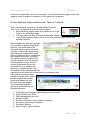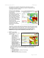
1
PM3 Deliverable: A05.1 ESS GmbH PM3 - Particulates monitoring, modelling and management LIFE09 ENV/CY/000252 Project Deliverable A05.1 Deliverable Number A05.1 Deliverable Name: Integrated Model System: Reference and User Manuals DDr. Kurt Fedra Environmental Software & Services GmbH A-2352 Gumpoldskirchen, Austria Due Date: PM 09, September 30 2011 Dissemination Level PU PP CO Public Restricted to other program participants (including the Commission Services) Confidential, only for members of the Consortium (including Commission Services) Page 1 of 95 X PM3 Deliverable: A05.1 ESS GmbH Introduction This Deliverable relates to Actions/tasks A05/5.2, Aerosol modelling, long range transport (using the 3D nested grid model CAMx) with inputs from tasks 1.3 (wind statistics as the major driving force) , 4.2 (emission estimates), and 4.3, (the DUST entrainment model), and A05/5.3Nested Grid Modelling (MM5, DUST, CAMx), which provide input to the emission control optimization (Actions A07, A08). The Deliverable describes the integrated model system, embedding the DUST emission model (see also: Deliverable DA04/4.2) into the AirWare (EUREKA E!3266 model framework. (for more detail, see the parallel deliverable DA05/5.2 that describes the operational implementation of the model system), and provides an introduction to the embedded hypermedia on-line manuals, embedded with the on-line web implementation of the models system. Technical aspects of the deliverable All results and associated interactive model and analysis tools are accessible from the PM3 model home page: http://www.ess.co.at/LIFE. The manual pages are implemented a hyperlinked HTML pages, that can also include links to animations (mpeg files), and in principle, sound files. Every manual page can also include any number of further links to related Manual pages or the GLOSSARY, and, in principle, any other external web page through the appropriate URL. The integrated model system is based on AirWare (http://www.ess.co.at/AIRWARE), mainly developed in the EUREKA projects E!1388 AIDAIR, and its follow-up, E!3266 WEBAIR (http://www.ess.co.at/WEBAIR). While not all components of the AirWare system are relevant (and used) for the PM3 LIFE project, the main extension for PM3 is the integration of the DUST model (see Deliverable DA04/4.2) in the central MM5-CAMx nested grid model system, and its inclusion in the optimization model component. The basic philosophy of the embedded hypertext manual page is a combination of rapid prototyping (as part of the OO development philosophy) concurrent requirements engineering. The manual pages and their continuous updates and additions are understood as a service (part of system support and maintenance) more than a product. A link to an on-line problem reporting system will be provided to help users submit questions, Page 2 of 95 PM3 Deliverable: A05.1 ESS GmbH comments and problem reports to the system, including the manual pages, which will trigger a specific update or extension of the respective component. On-line Manuals: Implementation and Table of Contents While the individual screens of the web interface provide links to the corresponding specific manual pages, Each individual page include in its header a link to the Table of Contents start page; The start page can also be directly addressed, leading to all primary manual pages (which in turn may contain further links in the hypertext system. Manual pages are centrally managed (for a number of parallel application servers), and distributed to the individual servers with incremental changes. A daily test compares the latest changes (modification dates) with the individual server installations and updates whenever necessary. The update system compares the central repository with the manual implementation on any (local or remote) application server, and generates a list of updates due, missing or unexpected files. The Subsequent script manages the files transfers and any deletions or redundant or unexpected files. Each individual manual page includes a header that shows the last release the manual page was updated for, and the date of the last update. The embedded hypertext manual is structured into the following sections: 1. 2. 3. 4. 5. 6. 7. 8. Third-party documentation and background documents Expert System and DSS Data Management and GIS Monitoring data Emission inventories and emission modeling Scenarios and Scenario Analysis Simulation Models Model output, impact analysis Page 3 of 95 PM3 Deliverable: A05.1 ESS GmbH User Manual/Tutorial The Reference manual is designed as a hierarchically structured hyperlinked document that covers both the reference manual (including information for system administrators) and the average, infrequent user. While the first page on every topic provide a basic description of background and functionality/use, optional links on each page lead to further, detailed material for experienced users and system administrators. CourseWare eLearning environment In addition to the on-line embedded Reference manual, an interactive Tutorial implemented in a web-based eLearning system is under development. This adapt course material from AirWare training sessions and a seminar “Urban Ecology” at the University of Innsbruck (LV: 825073), offered every winter semester. The lectures consist of a conditional sequence of dynamically HTML page and integrated questions and tests. The tutorial/course content is dynamically structures in response to learner behavior, using a real-time rulebased expert system to drive the “Socratic Dialog” engine. In addition to individual questions of embedded test sequences, the web based (hypermedia) course content can include video, animation, but also links to specific model components and tools, offered as on-line exercises as part of the tutorial. The course content also links to the Model Glossary (also linked from http://www.ess.co.at/LIFE) for the explanation of any technical terms and concepts introduced. Page 4 of 95 PM3 Deliverable: A05.1 ESS GmbH Reference Model structure and content The Reference manual is structured into the following eight main sections: 1. Third-party documentation and background documents 2. Introduction, installation, configuration 3. Expert System and DSS 4. Data Management and GIS 5. Monitoring data 6. Emission inventories and emission modeling 7. Scenarios and Scenario Analysis 8. Simulation Models 9. Model output, analysis, impacts Please note that the structure is based on a simple HTML page, and thus easy to modify to adapt to any specific application/implementation, based on user feedback. 1. Third-party documentation and background documents This section refers to the various on-line manuals for the embedded public domain models (MM5, WRF, AERMOD, CAMx). The manual also links to related documents, compiled in the on-line PDF library, currently holding 654 titles with the primary classification: air. The documents in the PDF library include basic bibliographic reference, keyword classification, an abstract, and a copy of or link to the on-line PDF document for online reading or optional download. The library is open for users (excluding guest) to upload new documents or suggest modification to the classification and keywords. Page 5 of 95 PM3 Deliverable: A05.1 ESS GmbH 2. Introduction, installation, configuration Introduction AirWare is an interactive information and decision support system for urban air quality assessment and management. It is developed in a series of parallel and synergetic projects, including: the EUREKA Projects EU1388 AIDAIR and E! 3266 WEBAIR the Telematics Applications Project ECOSIM the EESD City-of-Tomorrow project SUTRA a number of related research and development projects, see: http://www.ess.co.at/docs/gallery.html The current AirWare system is implemented as a distributed client-server system that supports web access from any industry standard browser, networked computer or mobile device (SmartPhone, tablet). Servers: Linux (Open Source) or Unix platforms Clients: any PC or workstation running a standard web browser, mobile devices (SmartPhones, tablet, NetBook) with Internet access and a standard browser. Installation notes AirWare is installed as a client-server web application, using an Apache web server (2.2.9 or); several data bases (implemented with MySQL (5.0); Alternatively: PostgreSQL, ORACLE); PHP (5.2.6) a number of cgi's (with the models and analytical tools; various data and configuration files: o /gis: map data o /var/www/html//MANUALS/AIRWARE: manual pages and imagery o /var/www/html/templates: HTML templates for OBJECT display. configuration of the scheduled tasks in several crontab files. The system [APPLICATION] is located under the Apache httpd server root directory: /var/www/html/[APPLICATION] and the model cgi's in: /var/www/cgi-bin which includes the configuration files for the scheduled model runs. Configuration files PHP include files file: /var/www/html/phpincludes/config.inc.php /* user, host, password used by php scripts */ Most of the entries are referring to localhost and thus should work in any installation, unchanged. The following entries need location specific adaptation: $java_host=[JAVAHOST]; << localhost does not work here!!>> $db_user['[DBSERVER]']='root'; $db_password['[DBSERVER]']=''; Page 6 of 95 PM3 Deliverable: A05.1 ESS GmbH Data Base (MySQL) configuration file: /var/www/cgi-bin/db_config /* default cgi database connection */ host user password port-number 3306 default Color configuration file: /var/www/cgi-bin/mapcolors /* substance specific color ranges for model results display*/ default color scheme with equidistant color ranges, dynamic range definition pre-defined, static, non-linear substance and aggregation-time specific color schemes. file: /var/www/cgi-bin/colorranges /* default lower and upper bounds for dynamic color ranges */ This uses the following format: ANY ANY 1 100 POLLUTANT_NAME PERIOD MIN MAX where the first record contains the definition of a global default, used when the dynamic scheme is selected, but no default definition corresponding to the current combination of substance/aggregation period can be found. Exposure thresholds A similar file defines the exposure thresholds for the computation of population exposure: /var/www/cgi-bin/exposurelimits which is again a simple ascii file with the format: ANY ANY 100 POLLUTANT_NAMEPERIODTHRESHOLD which defines: the pollutant or index the aggregation period the default threshold where the first record with ANY, ANY defines a global default if no specific value for a given combination of substance and aggregation period can be found. The values are defined in the unit that is associated with the respective pollutant or index in the Knowledge Base. CAMx model configuration Parameter files needed by CAMx: /var/www/html/templates/camx/data/ CAMx5.4.chemparam.4_CF CAMx5.4.chemparam.NOx CAMx5.4.chemparam.SO2 CAMx5.4.chemparam.CB4 CAMx5.4.chemparam.PM10 rate.2002164.do.mech3 topconcCB5.dat topconcPM10.dat topconcSO2.dat topconcNOx.dat Page 7 of 95 PM3 Deliverable: A05.1 ESS GmbH topconcPM2_5.dat Shell scripts Shell scripts for running interactive, Nowcast and Forecast scenarios: /var/www/cgi-bin/camx/ runcamx.sh runNowcast.sh runNOxForecast.sh runO3Forecast.sh /var/www/cgi-bin/aermod/ runaermod.sh runNowcast.sh Model CGIs cgis are located in /var/www/cgi-bin/MODEL in sub-directories under the corresponding model of function group name. For tabular summary and description, see: http://www.ess.co.at/MANUALS/AIRWARE/modelcgis.html DUST specific cgis are located in /var/www/cgi-bin/dustent and include: main.cgi main emission calculations cal.cgi calibration options new.cgi new scenario constructor pick.cgi readback and results for a specific location Shell scripts Shell scripts for running interactive, Nowcast and Forecast model scenarios are located in the corresponding model or function specific sub-directories under cgi-bin; please note that the DUST model is triggered by the CAMx script as part of the emission pre-processing; /var/www/cgi-bin/camx/ runcamx.sh runNowcast.sh runNOxForecast.sh runO3Forecast.sh /var/www/cgi-bin/aermod/ runaermod.sh runNowcast.sh For the application specific scripts, refer to http://80.120.147.34/MANUALS/AIRWARE/scripts.html Data bases Several data bases (implemented with MySQL (5.0); Alternatively: PostgreSQL, ORACLE) are used for data management and the communication between the different models. They include the following data bases: mysql information_schema AERMOD AIR mysql system data base mysql system data base AERMOD model scenarios, for sequences of 24 hourly runs emission sources: plants, boilers, small stacks, line and area sources Page 8 of 95 PM3 Deliverable: A05.1 ESS GmbH AIRDESCRIPTORS Knowledge Base: descriptors AIRMATRIX model output and emission matrices(by model/domain, parameter, time step, and layer) CAMx CAMx model scenarios CONTACT address DB for source contacts COUNTRIES countries for address DB (source contacts and institutions) DOMAIN model and emisison inventory domains GLOBAL general configuration GLOBAL_LOG log of model runs MM5 MM5 model scenarios MODEL_TS timeseries descriptors (parameters used in the monitoring time series) MONITORING_TS timeseries data RBO object class information, monitoring stations, timeseries TEHRAN census/population data for census tracks (polygon/areas) USER_MAN User/access management gis individual (user configured) maps mapc GIS meta data, map set, overlays for a list of the data base TABLES in each of these data bases, please refer to http://www.ess.co.at/MANUALS/AIRWARE/databases.html Data requirements The basic requirements to set up an AirWare system and configure and run the models are as follows: 1. Domain definition: o Definition of the geographical scope/area, background maps including the definition of the individual city/industrial areas of interest, land use, topography (DEM); 2. Monitoring data: o Meteorological data (minimally for one reference year) at an hourly resolution: wind speed and direction air temperature precipitation early-morning soudings, (optional) hourly mixing height, please note that these can be estimated from (optional) cloud cover data alternatively. Please note that alternatively, meteorological data can be generated by a prognostic meteorological model (MM5, WRF) driven with global GFS data from NOAA on a daily basis. These data can either be used as dynamic data fields (multi-layered) or by extracting meteorological parameters into existing or simulated meteorological monitoring stations. o Air quality observation data (matching the emission and meteo data sets !) including station locations. 3. Meteo forecasts: to run the model(s) in forecast mode, dynamic boundary conditions (met data for selected grid points within the domain) from an appropriate regional meteorological forecasting model are required. The meteorological forecasts can optionally be suplied by the prognostic meteorolgical model MM5 Output from MM5 is Page 9 of 95 PM3 Deliverable: A05.1 ESS GmbH generated to a 3 km, hourly resolution, automatically interpolated further with MM5toCAMxto a 1 km resolution by use with the CAMx nested grid air quality model. 4. Emission data: o Point (stacks) and area source emissions, locations, source (stack) characteristics, emission rates for any or all pollutants covered. Additional (alternative) data include fuels and fuels consumption, combustion technologies, industrial classifications, etc. o Transportation graph/network with link specific data (frequencies) as well as global properties such as fleet composition; o Fugitive emission from the fuel system including parked cars, gas stations. Alternative: traffic emission grid; o Emission inventories for (industrial) point sources and fugitive emissions, and area sources (domestic heating); o For the ozone modelling (PBM photochemical box model; for the 3D (optional) dynamic CAMx model see below): Hydrocarbons, divided into the following eight groups: Non reactives, Ethilene, Olefines, Alkanes, Formaldehyde, Aldehyde, Aromatics and Toluene; and CO, NOx (fixed ratio between NO and NO2), data for biogenic VOC emissions. o DUST model: wind field (dynamic MM5 or WRF output) soil moisture (MM5/WRF generated) DEM (30 meter resolution land cover, vegetation (several alternative data sources) 5. Population data: o Population distribution (for exposure analysis) by census tracts or larger administrative entities, or gridded (1ha to 1 km2); 6. Receptor points: for the monitoring of compliance with standards, model performance (validation), and impact assessment a number of receptors should be defined. These are: o Air quality monitoring stations o Building points (user positioned arbitrary receptor points) o Receptor areas (user defined arbitrary polygons). 7. Economic data: o Cost functions for emission reduction strategies, by emission class of major (point source) object or traffic related (fleet composition). 8. Logo(s) and start-page image. For the model specific data requirements and default data sets used for the individual models, please refer to the model specific descriptions. Page 10 of 95 PM3 Deliverable: A05.1 ESS GmbH User Management ASP systems provide their own user management and authentication system in addition to the Linux operating system level - that can be configured to provide selective access for local or external users to different levels of functionality in the system. User access is based on the concepts of GROUPS and SERVICES: a user belongs to a group which has read-write access to set of services provided by the system. User administration is only accessible to admin group users. The link to the user administration tools is on the <b<="" b="" style="font-family: Arial, sansserif; ">of the respective application.</b The primary access to the tool is a list of current users. The listing provides user name, first and last name, creation date, status (activated or not) and the last access date for the user. The auxiliary buttons are GROUPS and NEW; NEW offers and empty template to add a new user; GROUPS edits groups and the associated service access rights. For details, see: http://www.ess.co.at/MANUALS/AIRWARE/useradmin.html Model Accuracy Model accuracy is usually determined by comparing model results with air quality observations; the basic problems encountered are primarily related to 1. the intrinsic uncertainty of the observations themselves and their sample nature; 2. the vastly different scales involved when observing and modeling a turbulent process. While monitoring data describe concentrations over time at a point location based on small volumes (several liter) of air samples, the model estimates average concentration within a time step (e.g., an hour) for a comparatively very large volume of air (usually several million liters), under assumptions of complete mixing within the model grid cell/volume or as resulting from a (tenous at best) steady state assumption. Annex I of 2008/50/EC defines Data Quality Objectives, but none are defined for modeling in the context of PM10 or PM2.5 other than for the annual average: 50%. In general, the Directive states (Annex I): “The uncertainty for modelling is defined as the maximum deviation of the measured and calculated concentration levels for 90 % of individual monitoring points, over the period considered, by the limit value (or target value in the case of ozone), without taking into account the timing of the events. The uncertainty for modelling shall be interpreted as being applicable in the region of the appropriate limit value (or target value in the case of ozone). The fixed measurements that have to be selected for comparison with modelling results shall be representative of the scale covered by the model.” Page 11 of 95 PM3 Deliverable: A05.1 ESS GmbH AirWare offers two mechanisms to compare monitoring data and model results for the grid cells containing the monitoring station: Model scenario pages: the button Compliance at the model scenario levels leads to a pop-up window that provide a tabular listing of all monitoring stations in the domain with their measured values (if available for the current model time step) and the model generated values as well as the respective air quality standard for the current substance and temporal aggregation; the top of the window shows the comparison of measured versus simulated for the 24 hourly values of the scenario. Time series data analysis: in the time series analysis (display and analysis of a single time series) the time series of observed data can be compared with model generated values for that location if the model was run for the period selected. The two time series are shown in a common graph for direct comparison. The tabular summary on the left side includes a selection of (applicable) error statistics. Pollutants AirWare can represent any number of pollutants, as well as air quality indices such as PSI, as well as the PSI contributions of each of the five pollutants used as the basis for the PSI calculations (PSIP): the set of pollutants covered is completely open for monitoring data and emissions. AirWare uses an open list of pollutants. These can be grouped into two distinct classes: 1. Pollutants emitted (which includes CO2 and VOC, but excludes ozone) 2. Pollutants modeled (which includes O3, ozone, but excludes CO2 and VOC) The list of pollutants considered is, in principle, open and defined in a Descriptor in the systems Knowledge Base and can be changed by the system administrator. However, numerous and complex dependences make changing that list nontrivial. The basic list of pollutants considered in the emission inventories the emission factors for stationary combustion and road traffic include: CO, CO2, SO2, NO, NO2, NOx, PM10, PM2.5, VOC For the individual models, there are restrictions based on the specific substance behavior and the corresponding model processes. Page 12 of 95 PM3 Deliverable: A05.1 ESS GmbH PSI contributions: In addition to the PSI index value (based on data over the last 24 hours, the following individual subtance data are available as "individual pollutants" on an hourly, moving average, basis: CO: maximum of the 8-hour-averages of the last 24 hours (in reference to the timestep) O3: maximum of the 1-hour-averages of the last 24 hours (in reference to the timestep) NO2: maximum of the 1-hour-averages of the last 24 hours (in reference to the timestep) SO2: 24-hour-average (ending at the timestep) PM10: 24-hour-average (ending at the timestep) The basic set of pollutants can be grouped in terms of their behavior: 1. Physical properties: o bouyant, dense/heavier than air (heavy gases, particles); 2. Chemical properties: o conservative o first order decay, transformation (e.g., NO=>NO2, SO2=>SO4) o complex photochemistry (NOx+VOC=>O3) Emission inventories for point, area, and line sources should include: 1. CO2 (for statistical purposes only) 2. SO2 3. NOx (or NO/NO2) 4. CO (for traffic) 5. PM-10, PM-2.5 6. Volatile Organic Compounds (VOC), fugitive from area and line sources. The latter group is broken into a number of sub-groups or species, based on a speciation table that can be associated with any source class, type, or individual source. The global default speciation table includes: TOG (Total Organic Gases) is calculated from VOC: TOG = factor*VOC (default: factor=1); values above one represent the Methane fraction. The mass speciation factors for TOG are defined in the default profile (#0) which can be overloaded by emission source class, type, and individual source. (Source: http://www.epa.gov/ttn/chief/emch/speciation/) ALD2 Higher Aldehyde, based on Acetaldehyde 0.02 ETH Ethene 0.05 FORM Formaldehyde 0.02 OLE Olefin carbon bond C=C 0.05 PAR Paraffin carbon bond C-C 0.49 TOL Toluene and other monoalkyl aromatics 0.05 XYL Xylene and other polyalkyl aromatics 0.04 NR non reactives 0.28 Page 13 of 95 PM3 Deliverable: A05.1 ESS GmbH PSI air quality index In addition to the basic set of air pollutants, AirWare can also compute and display air quality indices such as PSI. PSI requires values from several pollutants and for different aggregation periods that are generated by the photochemical model CAMx, both a daily forecasts and as hourly nowcasts with the corresponding moving averages over the most recent 24 hours, including the current hour. 1. All CAMx result matrices show averages over a time period. The period can be 1 hour, 8 hours or 24 hours. All matrices are assigned to their ending time. For example, the 8-hour-average-matrix of 10:00 - 18:00 is assigned to 18:00. The 24-hour-average-matrix of September 29th, 7:00 - September 30th, 7:00 is assigned to September 30th, 7:00. 2. For calculation of PSI matrices the following matrices are generated for each timestep: o CO: maximum of the 8-hour-averages of the last 24 hours (in reference to the timestep) is taken for each grid cell. o O3: maximum of the 1-hour-averages of the last 24 hours (in reference to the timestep) is taken for each grid cell. o NO2: maximum of the 1-hour-averages of the last 24 hours (in reference to the timestep) is taken for each grid cell. o SO2: 24-hour-average-matrix (ending at the timestep) is taken. o PM10: 24-hour-average-matrix (ending at the timestep) is taken 3. The concentration values are transformed into PSI values using the following formula: psip = ( psi(hi) - psi(lo) ) * (concp - bp(lo) ) / ( bp(hi) - bp(low) ) + psi(low) where: psip calculated psi index for the pollutant concp the concentration of the pollutant bp(lo) lower breakpoint of the interval of pollutant concentration bp(hi) higher breakpoint of the interval of pollutant concentration psi(lo) PSI values corresponding to bp(lo) psi(hi) PSI values corresponding to bp(hi) bp(lo), bp(hi), psi(lo) and psi(hi) are taken from the PSI color definition. If the concentration is above the upper limit of the table, PSI is not defined. In this case the maximum PSI value + 1 is assigned (psip=301 ) 4. PSI matrix is generated by taking the maximum of the psip value of the 5 pollutants for each grid cell. Particulates For the calculation of particulates (PM10) AERMOD uses the fraction of particle mass emitted in the fine class, less than 2.5 microns, the representative mass mean particle diameter in microns. Page 14 of 95 PM3 Deliverable: A05.1 ESS GmbH The following default values are applied: 1. If no PM2.5 emissions are specified for a source, the default value of m(PM2.5)/m(PM10) = 0.4 is used. 2. Default value for mass mean particle diameter for PM2.5 (fine fraction): Dmm(PM2.5) = 2.0 3. Default value for mass mean particle diameter for PM10 (coarse fraction) without PM2.5: Dmm(PM10-PM2.5) = 7.5 4. Using the default value of m(PM2.5)/m(PM10) (0.4)leads to a default average particle diameter Dmm(PM10) = 5.3 CAMx: Dust is split into 'Fine Crustal'/'Coarse Crustal 50/50 for CAMx input. PM10 is split into 'Fine Other Primary'/'Coarse Other Primary' as before. Next forecast run will use the new input. For the DUST model, the following (primary, initial) default sizes are associated with the soil fractions derived from the FAO data: Sand (coarse soil fraction) 2.00 – 0.060 mm Silt (medium soil fraction) 0.06 – 0.002 mm Clay (heavy soil fraction) < 0.002 mm Emission Scenario: Column header from in the summary now reads: "Matrix". "PM10" - pyrogenic PM10 emissions from emission sources, "dust" - dust emission from dust entrainment. In case complex sources exist for the project, an additional column showing complex sources emissions is added. For the details of different representation mechanisms for particulates in CAMx, please refer to the model specific description or the on-line CAMx User Manual. Air Quality Standards AirWare supports any set of user defined air quality standards (defined in the application specific configuration files, see above). The standard are used for the evaluation of model results (at simulated monitoring stations) or monitoring data time series. For the implementation for Cyprus and the PM3 project, based on 2008/50/EC, please refer to: http://www.ess.co.at/LIFE/standards.html Pasquill Stability Classes Only applicable to AERMOD, not used in PM3 ISIC Rev 4.0 codes For a description of the ISIC code (used for emission source classification), please refer to: http://unstats.un.org/unsd/cr/registry/regcst.asp?Cl=27 Page 15 of 95 PM3 Deliverable: A05.1 ESS GmbH 3. Expert System and DSS XPS: Expert System The embedded expert system can server a number of functions: estimation of parameters, e.g., for simulation models; checking completeness, consistency, and plausibility of user specifications; interpretation of complex (model generated) data sets. real-time control of scheduled and event-driven complex and conditional task sequences. The expert system uses Descriptors as its basic variables, which are linked in processed in Rules. Main System Components are defined in separate manual pages, linked from http://www.ess.co.at/MANUALS/AIRWARE/xps.html DESCRIPTORS: the variables of the expert system RULES: first order nested production rules KB editor: interactive Knowledge Base editor Knowledge Base Editor A dedicated editor is available to manage the Knowledge Base (Descriptors and associated RULES) for the embedded XPS backward chaining expert system. The primary selector shows the Descriptors available, which can be sorted by name, author, or modification date. With every Descriptor name, the basic meta data attributes such as name, owner, and modification dates are shown. For the descriptor, an interactive editor is available. The editor compiles the meta data name, description, author, creation and modification dates, and descriptive information such type and format, and unit where applicable. The descriptor definition includes: the legal values (symbols and numerical ranges); the question text that is used in the editor tool (Java applet); the list of associated rules. The editor also offer s preview function for the definition. The preview shows how the definition is interpreted by the interactive editing tool (a Java applet) that uses the Descriptor definition to configure the tool used to set a specific value. The rules associated with a Descriptor fall into two groups: Rules that set that Descriptor Rules that use the Descriptor. These are first order production rules, implementing first order logic principles or modus ponens. The list of rules leads directly to the editing tool for RULES. A dedicated editor assists in formulating syntactically correct RULES. Page 16 of 95 PM3 Deliverable: A05.1 ESS GmbH Within a given template, the user can select the possible values for operators and symbolic variables (Descriptors) that can be used in the IF-THEN Rules, including nested AND and OR clauses. KB: Descriptors The facts (data) of expert systems XPS and RTXPS are stored in DESCRIPTORs. A value is assigned to a DESCRIPTOR either by direct editing or by starting the rule-based inference, that will recursively compile information from the data base including asking the user where necessary, to assign a value to the target (Descriptor) of the inference. The system then uses a set of alternative methods enumerated in the DESCRIPTOR definition to obtain or update the DESCRIPTOR value in the current context. The inference engine compiles all necessary information for the appropriate Backward Chaining Rules' input conditions recursively, evaluates the Backward Chaining Rules, and eventually updates the target DESCRIPTOR. Descriptor syntax and descriptions Descriptors are defined in terms of: an internal name used by the code, not to be changed a DISPLAY NAME freely changeable by the user; a UNIT (text string) A TYPE. Currently supported types: o V (variable, text only values), o H (hybrid): numerical ranges and associated symbolic range; o S (symbolics: list of symbols only. META DATA: user, modification date, explanatory text. TABLE of legal value ranges (type dependent); The legal range is defined from the lower bound of the first to the upper bound of the last range. The range definitions include triplest of numbers minimim - median (display) - maximum values, followed by a symbolic description of the range. Range definitions must be contiguous; the upper bound of the lower rangte must be identical to the lower bound of the following range. Median (display default) values are optional, but must be between (including) the upper and lower bounds for the range If no median value is defined the arithmetic mean is used. Question: HTML style text that is shown in the Descriptor editor. KB: Rules Backward Chaining Rules define how values for DESCRIPTORs are derived from values of other DESCRIPTORs, user inputs, simulation model results or other information available (data bases, GIS, etc.). Rule Syntax RULE <rule#> IF <condition> Page 17 of 95 PM3 Deliverable: A05.1 ESS GmbH THEN <action> ENDRULE <condition> := <condition <logical operator> <condition> := descriptor <comparative operator> <operand> := descriptor <singular operator> := TRUE <action> := descriptor = <operand> := descriptor <meta operator> <constant> <operand> := <operand> <arithmetic operator> <operand> := descriptor := <constant> <logical operator> := AND | OR <comparative operator> := < | > | <= | >= | == | != <singular operator> := EXISTS | NOT_EXISTS <arithmetic operator> := [ | ] | * | / | + | <meta operator> := INCREASES_BY | DECREASES_BY := BECOMES <constant> := string := number Rules can result in the absolute assignment of DESCRIPTOR values, their relative, incremental modification, or they can be used to control the inference strategy depending on context. Rules can also include simple formulas; more complex functions can be used through the generic model interface. An example for a rule used in the reservoir expert system is: RULE 1020231 IF average_reservoir_depth == small AND retention_time < 30 THEN reservoir_stratification = unlikely ENDRULE Also, the user can call up a knowledge base browser, that allows to navigate in the tree structure of the knowledge base within the context of individual problems. The browser can descend the inference tree, displaying sets of rules referring to a list of DESCRIPTORs and allow to inspect individual DESCRIPTOR definitions. The possibility to integrate models in place of rules in an expert system and at the same time use embedded rule-based components in models provides a very rich repertoire of building blocks for interactive software systems. RTXPS Real-time System RTXPS is a forward-chaining expert system operating in real-time (time aware): the forward chaining loop is executed continuously, and several function obtain, compare and use variables based on Absolute (systems) and Elapsed Time, including user defined TIMERS. This makes it possible to execute sequences of conditional and scheduled tasks with complex interdependencies, including the execution and Page 18 of 95 PM3 Deliverable: A05.1 ESS GmbH interpretation of dynamic simulation (forecasting or operational control) models, or ACTIONS based on the values of remote (real-time( sensors. RTXPS can be run in two distinct modes: 1. automatic, autonomous, continuously; here the forward chaining loops runs continuously, and is controlled only bythe RULES and ACTIONS executed; 2. interactively, which include functions that trigger display, interactive editors, and user dialof in general. Here, the forward chaining loop can be controlled by the user with interactive input: whenever input from the user is requested, the system will wait for that input, unless a TIMEOUT is defined for the dialog with a default continuation without interactive user input. A special case or application of RTXPS is CourseWare, an interactive webbased distance learning tool. On the basis of available rules, RTXPS decides which action is to be conducted next. Actions consist of up to 3 function out of which one should create a html page which is sent to the client. Pages can contain in-text functions - tools to display or edit descriptors or graphical elements which are created dynamically. Files and data bases The basic files for RTXPS are located in the (default) directory: /var/www/RTXPS RTXPS contains the rtxps.cgi executanle, and the following subdirectories, KB knowledge base bin script and functions as part of ACTIONS defaults configuration files logs dynamic log files RTXPS uses for its operation: the RTXPS executable, rtxps.cgi located in the base directory /var/www/RTXPS; the RTXPS executable is started manually, but can be included in the rc.* scripts for automatic start-up at boot time; please note that RTXPS needs to be retsarted whenever the knowledge base changes. A dynamic Knowledge-Base that stores the current state of the system in the data base; The Knowledge Base configuration files in /var/www/RTXPS/KB: these include: KBconfig: a knowledge base configuration fil, the sets the maximum dimensions, and enumerates the different files to be use, multiple entries will be concatenated in the sequence of their listing; MaxNr-Of-Descriptors:100 MaxNr-Of-Rules: MaxNr-Of-RTRules: 100 MaxNr-Of-Actions: 100 100 Page 19 of 95 PM3 Deliverable: A05.1 ESS GmbH DESCRIPTOR-FILES Descriptors END-DESCRIPTOR-FILES RTRULE-FILES Rules END-RTRULE-FILES ACTION-FILES Actions END-ACTION-FILES RTXPS Rules The forward chaingin RULES are very similar to the first order production rules used in the backward chaining version of the expert system, XPS. The main difference is the ACTION or consequence part: while in the backward chaining branch, this is always an ASSIGNMENTsetting the value of a DESCRIPTOR, the forward chaining system uses a repertoir of ACTIONS so that the general rule syntax looks like: IF [CONDITION] AND/OR [CONDITION] (evaluates to TRUE) THEN (execute) ACTION where ACTION can be an ASSINGMENT of the form: DESCRIPTOR == VALUE, any one of the built in FUNCTIONS; a user defined, named ACTION from the RTXPS ACTION Configuration file. Functions The consequence, THEN or ACTION part of an RTXPS RULE triggers an ACTIONtriggers an ACTION AN ACTION is either one of the built-in FUNCTIONS for a user defined, named ACTION. The built-in generic FUNCTIONs include triggers for simulation models, the backward chaining expert system, or external communication tasks such as data acquisition from monitoring systems or tasks such as automatic dialing for phone connections, or sending automatically generated eMail, fax or SMS messages. Other ACTION functions trigger special interactive editors to obtain information on more complex risk objects (such as trains, plants, etc.) which require specific dialogue windows for consistent editing of the attributes of the the risk objects and provide additional functionality such as links to on-line databases. From an implementation perspective there are two groups of functions: those defined in the library (and thus available in all applications) and the application specific FUNCTIONs only implemented for a specific application such as CourseWare. FUNCTIONs implemented in the expert system library: Page 20 of 95 PM3 Deliverable: A05.1 ESS GmbH set_descriptor_value(<descriptor name>,<value>) Initializes the DESCRIPTOR <descriptor name> with the specified value. Should the DESCRIPTOR already have a value set it will be overwritten with the new one. clear_descriptor_value(<descriptor name>) The value of the DESCRIPTOR <descriptor name> is cleared. The previous value (if present) is saved in the default value of the DESCRIPTOR. execute_rule(<rule#>[,<rule#>,...]) The backward chaining rules with the specified rule numbers (<rule#>) are fired in the given sequence until one of them has been sucessfully completed. At least one rule number must be specified. execute_rt_rule(<rule#>[,<rule#>,...]) All forward chaining rules with the specified rule numbers (<rule#>) are fired in the given sequence. Whenever an ACTION is set to ready the ACTION is automatically started and afterwards set to done. At least one rule number must be specified. export(<descriptor name>) The value of the DESCRIPTOR <descriptor name> is written to a file. The file is put into the subdirectory defined by the default "rtxps.fax.dir" in the directory specified by the log-files-path (defined in the CONFIG file of the application). The name of the file is the name of the DESCRIPTOR cut to its first 14 characters. If the DESCRIPTOR does not have a value the string *unknown* is written to the file. system(<descriptor name>) The value of the DESCRIPTOR <descriptor name> is run as a UNIX shell command in the directory specified by the default "rtxps.bin.dir". If the DESCRIPTOR value is emplty no command is executed. shell(<cmd>) The string <cmd> is run as a UNIX shell command in the directory specified by the default "rtxps.bin.dir". Interactive RTXPS sessions update_descriptor(<descriptor name>[,ask]) The value for the DESCRIPTOR <descriptor name> is set most commonly triggering the backward chaining inference engine, but more generally using the resources specified in its DESCRIPTOR definition (eg., backward chaining rules, data base access,...). Please note: depending on the parameters and current status of the dynamic knowledge base, the function update_descriptor() may also be applicable in an automatic, autonomous RTXPS sessions, see above. Page 21 of 95 PM3 Deliverable: A05.1 ESS GmbH The user is prompted only in case of missing information. If the value of the DESCRIPTOR has already been set before the function is called the value is not modified unless the update parameter is specified. Then the DESCRIPTOR AskBox is displayed showing the current value and the user can decide if he wants to keep the value, modify it, or re-run the deduction. display_html(<filename>) The content of the file <filename> is displayed in HTML format over the map display of the RTXPS screen. Position and extent are taken from the defaults also defining the position of the map display, ie., "rtxps.map.x", "rtxps.map.y", "rtxps.map.w", and "rtxps.map.h". close_html() The HTML display previously opened with the FUNCTION display_html(<filename>) is closed.< Timers (RTXPS) There are 3 predefined descriptors and several buil-in functions relating to time: 1. START_TIME: start time of the current RTXPS cycle, mainly used in interactive applications such as CourseWare or theRiskWare realtime emergency management applications. 2. CURRENT_TIME: system (local) time for the system defined time zone, including day saving time shifts, HH:MM:SS 3. CURRENT_UTC: global standard time (Zulu, UTC, GMT), HH:MM:SS 4. ELAPSED_TIME, difference between CURRENT_TIME and START_TIME. 5. MINUTE(number): : TRUE if the current minute from HH:MM:SS matches; 6. HOUR(number): TRUE if the current hour from HH:MM:SS matches; 7. DAY(number), DAYN(string): o TRUE if DAY(number) argument matches the number of the day (1-31) within the current monthy. o TRUE if the string argument of DAY matches the threecharacter abbreviation for the current days name (system date function) as in SUN, MON, TUE, WED, THU, FRI, SAT, case insensitive; o MONTH(), MONTHM(); o YEAR() TRUE if the argumenrt matches the currenr year from date (YYYY). The Descriptor definitions (in the respective application's KnowledgeBase) are shown below, with the TIMERS being of the TYPE: variable. Page 22 of 95 PM3 Deliverable: A05.1 ESS GmbH RTXPS first creates dynamic knowledge base, then sets predefined descriptors to their current values. Implementation: CourseWare START_TIME and ELAPSED_TIME rely on the fact that the first action of every course calls function init(). These descriptors can be used for computation as well as display. The behaviour of value(ELAPSED_TIME) is equivalent to header in-text function\elapsed_time and behaviour of value(CURRENT_TIME) is equivalent to header in-text function \time. Besides user can define application specific time descriptors and set their value using rtxps function set_time(descriptor_name). All time descriptors can be displayed with rtxps in-text function \value whose format is hh:mm:ss or with rtxps in-text function \valuef which displays an integer number in seconds. There are two operations defined for time descriptors: addition: add_time(result,operand1,operand2) substraction: subst_time(result,operand1,operand2) see also: RTXPS functions Emission control technologies A data base of Emission control technologies, that are designed to be used in the optimization scenarios. Access to the data base is from within the AirWare ONBECT class selector, or directly (linked) from http://www.ess.co.at/LIFE Emission control MCA The Emission control optimization is currently based on PBM a simple numerical air quality model that simulates photochemical smog at an urban scale. For a given PBM scenario, the buttons EMISSIONS and in the emission scenario, optimize lead to the optimization interface. The optimization scenario is a standard OBJECT with header and META data. The scenario will list a set of sources, for which control options (emission reduction at at a cost) can be defined. The set of sources includes: 1. all boilers (major point sources from industrial plants) 2. small stacks (as a class) 3. area sources (as a class) 4. line sources (as a class). As a basic scenario control parameter, the user can define the number of runs to be made in the Monte Carlo framework. Emission control strategies for each of the emission sources or source classes, the user can edit: Page 23 of 95 PM3 Deliverable: A05.1 ESS GmbH F oINV rOP Ref annualized investment cost of the control policy or technology annual operating costs (OMR) reference unit for the OMR costs (time step) eReduction%the relative emission reduction achievable with a 100% (complete) application of the policy of technology a a minimum application rate cMin Max a maximum application rate h a weight factor that defines the probability that the instrument will Weight be applied Once a scenario is completely defined, it can be run with the run button. A message Running ..... will indicate the status, an optional eMail message will indicate completion for registered user with their eMail stored in the user data base. Optimization results When the set of runs specified by the user is completed, the results page (also accessible from the corresponding button) will be shown. The results list the summary over the set of model runs with the average application rate and associated investment and operating costs for each emission source or source class. The columns %min and &max indicate the minimum and maximum remaining emissions (as % of the original uncontrolled emissions) from the corresponding source. The button details generates a ranked listing of the model runs (alternatives) with a set of four (user selected) criteria displayed, the last one associated with a graphical representation (color coded horizontal bar) to symbolize the criteria value. The list can be sorted (ascending or descending) for any one of the criteria displayed. Selecting any individual alternative from the list will display its specific results, i.e., the various technology application rates, cost, and associated emission reduction. Post-optimal analysis To analyse the set of alternatives generated, the data can be exported to DMC a discrete multi-criteria DSS tool. The buttonexport will export a data set if results have been generated; The button DMC will directly lead to the corresponding DMC scenario. DMC: discrete multi-criteria The DMC tool is an interactive discrete, multi criteria optimization system, using a reference point approach and normalization of the decision space between nadir and uotpia. The sets of alternatives to analyze can either be: 1. imported as a set from WRM optimization scenarios (use the button: DMC" after a successful optimization run at the optimization scenario overview level to export the feasible alternatives generated); 2. imported individually from WRM model runs; 3. imported from a CSV file (exported from a spreadsheet) Page 24 of 95 PM3 Deliverable: A05.1 ESS GmbH 4. created (and edited) manually. Basic Concepts The tool operates on named sets of alternatives. Each alternative in an object that has a set of attributes or criteria that define it. The set of critiera or dimensions in decision space is the same for all alternatives within a set. The user can select or deselect any one of the criteria (with a minimum of two) for consideration or use in the analysis. Every one of the criteria used is define in the Knowledge Base (KB) associated with the tool. For each of the criteria, there is a (scalar) value defined an optimization strategy or direction (minimize, maximize, meet) defined; the latter case is a shortcut for minimizing the deviation in either direction from the reference, in this case, by default the median of the distribution for that criterion in the set. an (optional) constraint (upper or lower bound, or normalized distance depending on the strategy or direction of optimization) defined. The main concepts used include: feasible subset: the set of alternatives that meets all of the constraints; UTOPIA: a hypothetical point defined by the "best" value for each the criteria in the set. NADIR: a hypothetical point defined by the "worst" value for each of the criteria in the set; dominated subset: an alternative is considered dominated, if we can find another in the set that is better in at least one, and not worse in any other (i.e., at least equal), of the criteria. The dominated subset is identified and excluded from consideration. PARETO set: this consists of all non-dominated alternatives; Reference Point: a hypothetical point defined by the user who select his preferred value for each of the criteria. The default Reference Point is UTOPIA. Efficient Point: this is the feasible and non-dominated alternative "nearest" to the Reference Point. The distance is determined as the N (number of criteria) dimension Euclidean distance in the spce define by all (active) critiera normalized between NADIR and UTOPIA. The distance is described as a (normalized in %) level of achievement or (100% - distance): 100% would be UTOPIA itself, 50% halfway between UTOPIA and NADIR, and 0% would represent the position of NADIR. In addition to the achievement level of the efficient point, the tools also shows the (arithmetic) average achievement level of the PARETO set. Basic functionality 1. define the set, add and delete alternatives; with every new alternative, NADIR and UTOPIA may change; Page 25 of 95 PM3 Deliverable: A05.1 ESS GmbH 2. define the criteria, select or deselect from consideration; a good strategy is to start with two criteria only, and add critiera one by one towards a more complex problem. 3. introduce constraints on any of the criteria to limit the subset of feasible alternatives to be considered; 4. introduce a reference point different from its default (UTOPIA). The results is the efficient point, which is the current solution or the best non-dominated alternative, nearest to the reference point. Auxiliary analysis In addition to the graphical display of the set of alternatives with different colors for the different types of alternatives (NADIR (BLACK); infeasible (small dark GREY); dominated (larger light GREY), PARETO (GREENE); current (BLUE); efficient (YELLOW); and REFERENCE (RED), the tools shows either a summary of the optimization scenario with the import and configuration interface; a tabular summary and editor interface for an individual alternative selected from the main list of alternatives with the associated scatter-gram of all alternatives, the current alternative marked; a tabular summary of the set with the associated scatter-gram; an enlarge scatter-gram; the statistics for an individual criterion with a histogram, with the possibility to select a second criterion for a display of a scatter-gram and correlation (covariance) estimate. Criteria For WaterWare: The set of criteria can, in principle, be defined by the user interactively: criteria can be deleted from the set, and new ones can be defined in the Knowledge Base with the KB Editor and added with the RECONFIGURE button. These will be set to a value of undefined for all existing alternatives, which the user then can edit. For AirWare/PBM: the current set of criteria is pre-defined depending on the air quality model used. 4. Data Management and GIS Data Types AirWare includes a set of basic and composite data types and OBJECTS for which dedicated import, editing, analysis and display functions are provided. The data types include: 1. Descriptors are scalar, symbolic, numeric (with associated symbolic range definitions and defaults), or text variables that are managed by the embedded expert system and a dedicated interactive editing tool. Descriptors are used to define the parameters for more complex types such as: 2. Time Series which in addition to their numeric value have an associated explicit time stamp; Page 26 of 95 PM3 Deliverable: A05.1 ESS GmbH 3. Matrices, which in addition to the numeric value of each cell have a location (geo-reference) and geometry, including possible vertical layering, and again may have explicit time stamps. 4. GIS data (geo-referenced) including points, lines, topological networks, polygons, and rasters as individual map overlays and composite maps. 5. Hypertext including imagery, used to describe OBJECTS (see below); These basic data types are grouped into various composite structures or OBJECTS: OBJECTS are complex composites of basic and derived data types; examples for OBJECT classes in AirWare include: Monitoring Stations that contain time series data; Point Sources that hold emission data; Industrial plants, that combine several point and possibly area sources; Area sources of emissions; Line sources representing road segments; Road networks that provide a topological framework for line sources; Matrix objects, that manage the 2D data sets for the distributed models; Model domains that define areas of interest for simulation; Meteorological scenarios, that hold consistent and complete data sets for the simulation models, bound to a model domain and derived from monitoring stations. Emission scenarios, dynamically derived for a model domain; Model scenarios, that compile the above sub-scenarios and can trigger model and display and analyze their results; Object data base AirWare includes a general purpose OBJECT DATA BASE that manages geo-referenced or generic objects. A multi-attribute selector/navigator provides access to classes and instances, and support a range of filtering and sorting operations. The objects in AirWare are grouped by CLASS. The list of CLASSES is open and can be configured and extended easily. OBJECT CLASSES currently supported are: Monitoring stations Time series data sets; Meteorological scenarios (complete, consistent and synchronized data sets) Emission sources, including o point sources (boilers/stacks), o area sources, o line sources (road segments) Emission patterns Fleet compositions Page 27 of 95 PM3 Deliverable: A05.1 ESS GmbH Road networks (topological structure as used in transportation models) Industrial plants or installations (containers for point sources, possibly also parallel area sources for fugitive emissions); Model domains (geographically defined); Overlays and Maps (set of overlays in specific stacking order). Matrices (model input related) Each of these CLASSES may have any number of elements. Each class has a set of specific attributes, organized in a set of data structures and associated METHODS for instantiation and display. Selecting an OBJECT from the listing within a CLASS starts a display and editing page for the object. Data structures include 1. HEADER with name and id (mandatory), location, and meta-data information, common to ALL object classes; The LOCATION of the object is used, together with a specifications of EXTENT (a radius around it) to define a VIEPORT to generate a MAP of the surrounding of the object with the object diaplyed as a SYMBOL in the center of the MAP. 2. ATTRIBUTE SET that is class specific; they may include: o Hypertext including imagery for a detailed description; o Tables of Descriptors, using XPS library functions for editing and inference; o Time series of scalars, vectors, or lists; o Matrices o References to related objects (children or sibblings); Object header All OBJECTS have a HEADER, that includes their 1. Basic identification and short textual description, 2. META data (user, modification date). 3. geo-reference (and parallel map display of the OBJECT position where applicable in the main OBJECT display page driven by the OBJECT TEMPLATE, see also:OBJECT LOCATION); 4. (optional) symbolic geo-reference. Elements of the HEADER, common to all OBJECT classes, include: Object name, class, and a unique ID. Reference year (validity of the data). Description (free text) Owner (user with RW access), creation data, last modification date. Help file link (URL), class specific; Hypertext link (URL); (embedded display for the description page) Geo-reference: lat, long, elevation; Symbolic geo-reference: up to four tuples of administrative unit - unit name, usually: location (case study domain name used for geographical data filtering), province, community/city. From this set, any subset may be displayed depending on the layout for the object class: see also: OBJECT TEMPLATE). Page 28 of 95 PM3 Deliverable: A05.1 ESS GmbH Hidden attributes: o Mapset ID, leads to the selection of the background map shown. o Reference point, x/y in map coordinates, used for the positioning of the symbol shown. o Map extent around the reference point. o Display symbol or style (color, line style and width) reference o Type specific GIS coupling: area (polygon) or line segment for area and line sources, respectively. Object attributs Attribute sets consist of 1. Descriptors (which can be: variable, symbolic, or hybrid); their layout, format and editor interface is controlled by the class-specific TEMPLATE file and the variable (Descriptor) definition in the Knowledge Base. 2. Structures: these include more complex data structures with specific constraints (like summing up to 100% ...) such as time series, tables of different dimensionality, and matrices. Their layout is defined by a set of WIDGETS in or available to the PARSER cgi that is triggered by the respective TEMPLATE tags. or escape sequences. The TEMPLATE is responsible for the overall positioning of the widget. o Time series (references); o Temporal scaling factors (monthly, daily, hourly); o Contact addresses, contact persons; o Fleet composition; o VOC speciation (ISIC industry class specific); o Link lists to other, related objects. 3. Methods for the attribute instantiation in a dynamic context (scenario, absolute or simulation/scenario time) Object TEMPLATES Individual objects are displayed using HTML-style TEMPLATES that conreol layout and compile content (the attributes). The TEMPLATE to use for a given OBJECT class is defined in the data base RBO, table: CLASS. The TEMPLATE files themselves are located in the directory: /var/www/html/templates and service/application specific sub-directories, including: aermod boiler emission_pattern mapserver monitoring receptor_area windf airmodels building_points domain emission_report metamatrix small_stack timeseries animations camx emission line_source meteo pop traffic area_source camx_result emission_factor map mm5 powerplant The TEMPLATE is a standard HTML file; it is parsed before display, and specific escape sequences or tags to add dynamic content into the HTML file include: Page 29 of 95 PM3 Deliverable: A05.1 ESS GmbH 1. \include(template/standard_head.html) including any common files (in this case, for the common object header); 2. \name(DESCRIPTOR), which displays the display name: of the Descriptor DESCRIPTOR; 3. \ask(DESCRIPTOR), which will display the current value (including undefined) for the Descriptor as an active link in blue, which will trigger the editing dialog. 4. \value(DESCRIPTOR), which will display the current value (including undefined) for the Descriptor as a read-only string; 5. \unit(DESCRIPTOR), will display the unit of the Descriptor DESCRIPTOR. Object location Most OBJECTS are located in space can be geo-referenced In AirWare, the embedded GIS and MapServer provide background maps for the display of object location. The default background map is associated with the LOCATION of the application or project. For the display of a each object in space, the following data are used: 1. a reference point that defines the position; 2. a MAP ID that defines the map to be used (default associated with the project/application through the concept of LOCATION); 3. an EXTENT that defines a radius around the object that should be shown on the MAP; together with the reference point (x and y coordinates) this defines a VIEWPORT to use for the object/map display; 4. A SYMBOL ID that defines HOW the object should be shown on the map (default symbol: a red circle). Changing Position/Viewport and MAP ID To locate an OBJECT on the map, change the map extent to be shown around it, and compose/choose the background maps to be shown, and EDIT button at the OBJECT DATA BASE level map display leads to the COMPOSER. There the current (default) map with the current (OBJECT specific) location and extent are shown. The user can: 1. move the OBJECT position by clicking on any point on the map; the map will be redrawn with the new position in the center, the same background and extent subject to the constraint that the background map will cover the entire map window. 2. change the extend (FOCUS) around the OBJECT (subject to the constraint above; if the extent chosen exceeds the size of the underlying map given the current location/viewport, the object location will be shifted out of the center). 3. select an alternative background map by name from the pull-down menu; if no appropriate map is available, 4. compose a new background by selecting an alternative set of overlays at the MapComposer level and press the GENERATE Page 30 of 95 PM3 Deliverable: A05.1 ESS GmbH BUTTON; the new map will then be available in the MapCatalog and can now be selected from the above positioning pull-down menu. Upon RETURNING to the original OBJECT DISPLAY page, the (new) MAP ID, position, and extent around the OBJECT will be stored with the OBJECT and will affect the OBJECT map display. Model Domains All simulation model runs or scenarios are implemented for a certain area of interest, location and extent, or model domain. Also, from the master emission inventory, domain specific inventories can be generated. Domains are OBJECTS that can be selected from the OBJECT DATA BASE hierarchical selection/navigator tools. A domain usually will cover a specific area of interest such as a city, industrial district, part of the transportation system, the area around a major emission source like a thermal power station or major industry, or the entire region of an application. The domain definition provides a shared data structure to ensure the consistency between 1. all the geo-referenced data such as the emission sources, 2. a meteorological scenario, 3. model grid and sub-grids and thus geo-referenced output, 4. results post-processing such as exposure analysis. A Domain is a named object with the standard object MEATA DATA header. Due its multiple use by different models, scenarios, and also as embedded grid in CAMx, domains are READ ONLY and can only be modified by ADMIN group user. The attributes of a domain include: 1. Object META DATA including name and description; 2. Symbolic georeference (data driven set of administrative or geographical concepts such as region, province, community) 3. Location and (rectangular) extent, defined by: o Reference point X and Y (in the center of the domain) used to locate the domain; this is shown as the usual default OBJECT location indicator as a circle on the map, it can edited by ADMIN users, also used to locate the object on the map interactively; o Origin X and Y: map coordinates of the origin (lower left corner) of the domain, computed from reference and extent, read only; o Aspect ratio (symbolic selection between square 1:1 and landscape 4:3); o East-West extent or width in km o North-South extent in km (computed, read only) o area covered (in km², computed, read only) o the upper right corner is computed and stored/accessible in the data base, but not displayed. o Map margin (in % of the domain extent, generates a margin around the domain rectangle). Page 31 of 95 PM3 Deliverable: A05.1 ESS GmbH 4. Background map: MAP ID for the background map (hidden), the map can be selected interactively through the MapCatalog. The Domain is described by these attributes in tabular format together with the background map indicating the extent with the rectangular domain boundaries drawn on the background map. For a new domain, the ADMIN user can specify: name and description; select the aspect ratio and horizontal extent; select the map window size in % of the domain width; define the location of the reference point i(center of the domain); select an alternative background map from the MapCatalog.; Nested grid constraints CAMx uses a nested grid scheme to calculate results for sub-domain at a higher resolution. To make that possible, a number of constraints apply for domain that are to be used as sub-domains with CAMx. See also: Configuration of Scheduled Scenarios. 1. The domain must be square; 2. The corner point must be positioned on a 3km master grid node; 3. The domain size (extent) must be modulo 3. Matrix Objects Spatially distributed models require spatially distributed input data, and produce spatially distributed results. In AirWare, all model related spatial data use the same, common data format and are described as matrix OBJECT. Matrix objects are read-only, they are generated by mode pre-processors or are model generated output. Matrix objects (which can contain one or mode 2D matrix) are selected from a standard selector/navigator, selection properties rea: matrix name model domain parameter (Descriptor) generation method generation date N of layers N of time steps A Matrix is a named object with the standard object MEATA DATA header. The attributes of a matrix include: Object META DATA including name and description; Class specific attributes include: o generation method (symbolic name of the pre-processor or model) o the model domain that provides location references; these include: map coordinates of the origin (lower left corner); aspect ratio (symbolic selection between square 1:1 and landscape 4:3); East-West extent in km Page 32 of 95 PM3 Deliverable: A05.1 ESS GmbH North-South extent in km (computed, read only) area covered (in km², computed, read only). o Matrix geometry: cell size (only square cells are supported; number of cells in X and Y directions. o Parameter (based on a Descriptor, the parameter is either scalar or a 2D vector in case of wind fields) o number of layers o time stamp of first (set of) matrices o number of time steps Statistics: average, minimum, maximum, non-zero average, histogram (10 classes, color coded with automatically generated rainbow colors also used for 2D display). Please note: a complex system of matrix analysis/comparison similar to the time series analysis is in preparation for future releases. Matrix display When a matrix is selected from the selector/navigator, its default display shows the first instance( lowest layer, first time step) color coded corresponding to the histogram. Selector/buttons (tape deck) support switching between layers and time steps. The matrix can also be shown in a full-size pop-up window for more detail. Matrix import An interactive import function supports the upload of matrices prepared by external tools such as a spreadsheet. Matrix export Model results matrices can be exported in CSV format with a 14 record header for META DATA. Matrix Export All spatially distributed models in AirWare produce their output as MatrixObjects. These matrices can be exported in CSV format using the export button at the details model results display page. The exported CSV file starts with 16 lines of header information with the META data describing the exported matrix: Source Resolution Substance Unit Start time Duration Interval Time steps Layers Components Rows Columns CAMx 1000 m NOx ug/m3 2008-08-25 19:00 24 hours 1 hour 24 1 1 300 300 Page 33 of 95 PM3 Deliverable: A05.1 ESS GmbH Domain name NW corner of domain (UTM coordinates) Domain extent in x direction Domain extent in y direction TEHRAN x=380000 m - y=4105000 m 300000 m 300000 m This is followed by the data (comma separated floats) for each grid cell. For each time step the matrix is given in the following format (time steps are separated by an empty line): Data start at the north-west corner of the domain. Each line corresponds to a row of the matrix containing values ordered from west to east: o The first value corresponds to the north-west corner of the domain, o The last value of the first line corresponds to the north-east corner. o The first value of the last line corresponds to south-west corner of the domain, o The last value of the last line corresponds to the south-east corner. Population data Population data are an OBJECT CLASS, associated with polygons similar to area sources. These data (usually from a census with associated census tracks as the spatial units) form the basis for the pollution data raster used for the calculation of population exposure. The primary entry from the object class selection leads to a ranking list of population objects, i.e., populated areas or census tracts. The listing shows the object names, an associated symbolics address (e.g., district) and the absolute and total population numbers. The associated map can be zoomed, and queried: to start the info mode, click the info button under the map, the click on any one of the color coded areas on the map. The name of the object will be shown. To return to the zooming mode, click the zoom button. Land use data Land use surface characteristics and associated roughness (length) as well as UV albedo are important inputs for CAMx. CAMx landuse categories and the default surface roughness values (m) assigned to each category by season. Winter is defined for conditions where there is snow present; winter months with no snow are assigned to the Fall category. Roughness for water is taken as the maximum of the baseline value given in the table, and the function Z0 = 0.000002 w**2.5 , where w is surface wind speed (m/s). The listed UV albedo values can be used to assign UV albedo from landuse data in preparing the albedo/haze/ozone (AHO) input file. Surface Roughness (in meters) and UV Albedo by land cover and season N Land cover 1 Urban 2 Agricultural Spring Summer 1.00 1.00 0.03 0.20 Fall Winter UV Albedo 1.00 1.00 0.08 0.05 0.01 0.05 Page 34 of 95 PM3 Deliverable: A05.1 3 Rangeland 4 Deciduous forest 5 Coniferous forest, wetland 6 Mixed forest 7 Water 8 Barren land 9 Non-forested wetlands 10 Mixed agricultural/range 11 Rocky (with low shrubs) ESS GmbH 0.05 1.00 1.30 1.15 0.0001 0.002 0.20 0.04 0.30 0.10 0.01 0.001 1.30 0.80 0.50 1.30 1.30 1.30 1.30 1.05 0.90 0.0001 0.0001 0.0001 0.002 0.002 0.002 0.20 0.20 0.05 0.15 0.03 0.006 0.30 0.30 0.15 0.05 0.05 0.05 0.05 0.04 0.08 0.05 0.05 0.05 Embedded GIS AirWare uses an embedded MapServer that manages a MapSet together with a MapComposer configuration tool to combine several individual topical overlays, over an optional raster background map. MapCatalog overview and map selection to associate named maps with OBJECTS and OBJECT CLASSES including model domains, o MapImport and overlay description tool, to provide geographical background and orientation/reference for its data (OBJECTS and spatial model inputs and results. In addition, a range of geo-referenced data that can be viewed as topical maps are used as model inputs. For the user, the MapServer is transparently embedded with all georeferenced OBJECT CLASSES, model scenarios and their underlying domains, model inputs data sets, and model results. Within a given application, a MapSet of available overlays is defined. A MapImport function is associated with the display and definition of the raw map layers or overlays, accessible from the central MapComposer. GIS formats supported for import include ArcView Shape files (topical maps, one topic at a time) Raster formats (TIFF). User interaction GIS related operations the user can perform include: 1. Map Composition from the set of individual topical overlays, including the definition of optional ViewPorts for individual named maps; 2. Map Import, interactive import of maps (raster format) or (single topic) topical map overlays from client PCs (please note that composite maps with several topics can be constructed with the Map Composition tool) 3. Map Catalog Browsing and selection of maps as the background for individual OBJECTS and OBJECT CLASSES including model domains; 4. Background Map Selection: interactive selection of background maps for 1. Model domains 2. all georeferenced OBJECT classes 3. all georeferenced OBJECTS (instances). Page 35 of 95 PM3 Deliverable: A05.1 ESS GmbH 5. Object Geometry: Import for Area Sources and Receptor Area polygon boundaries (single feature of a single-topic ArcView Shape file); 6. Object Geometry: Import for Line Sources polylines or line segments (single topic ArcView Shape file). 7. Object Location, definition of the location of point sources (or object with a reference point) directly on the map; MAP Set Maps are organized in an application specific MapSet. The MapSet defines: 1. the common projection for all maps 2. the common coordinate system for all maps 3. the bounding box for the application, which should coincide with the main model domain (AirWare) that covers the area of interest; 4. the location in the file system of the raw map data 5. the default map shown in the MapCompser and MapSet interface. The latter (the default map) can be changed by the user; all other features must be consistently configured by the administrator in the data base: Data bases, tables, and files DATA BASES: mapc, gis DATA BASE TABLES:mapset_data, overlay_data DATA PATH: user configured in the MapSet main page, default: /gis MAP Composition AirWare uses an embedded GIS or MapServer together with a Map Catalog and configuration tool (Map Composer) to provide geographical background for its data (OBJECTS and spatial model inputs and results. The Map Composer offers a choice of one background overlay (raster or polygon feature, opaque, full coverage, from a list of all applicable background overlays: only one can be chosen at a time) and all applicable foreground overlays line features, transparent polygon or raster, partial coverages, any number can be combined) together with a central point of interest (X and Y coordinates) and extent (in meters, interpreted as a radius around the central point of interest) from which a named MAP (configuration) can be generated for 1. preview (temporary) or 2. permanent storage Page 36 of 95 PM3 Deliverable: A05.1 ESS GmbH and retrieval/display from the Map Catalog for selection as default background for all geo-referenced OBJECTS. The list of overlays leads to a description and individual preview of any of the overlays listed by the Map Composer. Navigation BUTTONS 1. The BUTTON MAPSET leads to a description of the applications MapSett and its parameters (projection, coordinate system, bounding box) that are needed for Map Import. Also supports the definition of a default map for the MapSet, and the directory of all map data. 2. The BUTTON OVERLAYS leads to a listing of all available map layers or overlays, and offers the possibility to ADD/IMPORT a new overlay with the Map Import dialog. 3. The BUTTON MAPS leads to the Map Catalog. 4. The BUTTON COMPOSITION leads back to the main Map Composer level from any its secondary pages. If a MAP (configuration) is to be stored permanently in the Map Catalog, the user can specify a name before generating a permanent configuration. Other descriptive META data (creation date, user/owner, overlays used, projection, extent) are stored automatically with the new map. At the level of the Map Catalog, a more detailed (free) textual description of the map selection can also be entered. MAP Catalog The MapCatalog is accessible from the Map Composer level. The MapCatalog shows all MAP (configurations) that have been defined and stored as permanent as a thumbnail images together with their user defined short name and ID. Clicking on any one of the small MAP images lead to a pop-up page that shows that MAP (in its original viewport) in a larger window together with its META DATA (name, description, owner, creation and modification dates) as well as the list of overlays it was generated from, the parameter of its (native) viewport (center coordinates and extent defined as radius in meters) and the coordinates of the bounding box of the map. The maps shown can be selected as background map for 1. any geo-referenced OBJECT CALSS 2. any geo-referenced OBJECT 3. model domains and thus modeling results A SELECT button allows to select the MAP as the (new) background for an OBJECT that has called the MapComposer from the map display EDIT button at the OBJECT CLASS selection or OBJECT display level. From the set of maps shown in the MapCatalog, any individual maps can be selected and shown individually, in a larger window together with its legend, The SELECT operation changes the default (class specific) background map for the for an OBJECT or OBJECT CLASS, but retains its latest viewport (center point and extent). Page 37 of 95 PM3 Deliverable: A05.1 ESS GmbH MAP Import The import of maps or map layers/overlays is available as an option for NEW overlays, triggered from the MapComposer tool through the button: OVERLAYS. EXISTING overlays to replace their current data; specific OBJECT geometry representation: 1. line sources (road segments) 2. area sources 3. receptor areas. For an existing overlay from the list, an alternative map/overlay data set can be imported; they must conform to the parameters defined for the current MapSet in terms of projection, coordinate system, and extent (at least partly within the overall application bounding box). For a NEW map, map layer or overlay, the IMPORT button will trigger a dialog pop-up window where the users specifies (or select from browsing the local file system) a file name for the map data to be imported from the local client PC, browsing the local file system. GIS formats supported Vector formats ArcView shape files: import supported for lines and polygons one topic, one color, one line width at a time attribute table is ignored display color and line width can be selected Arc/Info export files: supported are single-precision, uncompressed files containing lines and/or polygons one topic, one color, one line width at a time attribute table is ignored display color and line width can be selected Raster formats tiff: import supports pseudo and true color uncompressed and compressed images. Supported compression algorithms, are: CCITT 1D Huffman compression , CCITT Group 3 Facsimile compression , CCITT Group 4 Facsimile compression , Lempel-Ziv & Welch compression , baseline JPEG compression , word-aligned 1D Huffman compression , and PackBits compression . In addition, several nonstandard compression algorithms are supported: the 4bit compression algorithm used by the ThunderScan program , NeXT 2-bit compression algorithm, an experimental LZ- style algorithm known as Deflate , and an experimental CIE LogLuv compression scheme designed for images with high dynamic range. Import Dialog 1. To import a map data set from the Overlay Description page, the user can first select the type: vector (the default) or raster. If a reaster (TIFF) is to be imported, the origin and extent have to be defined first, else and error message will be generated. In case of a vector coverage, the origin and extent will be determined automatically from the data imported. For a vector coverage, the type (shapefile or e00) will be determined automatically. The user can specify in the dialog box: Page 38 of 95 PM3 Deliverable: A05.1 ESS GmbH line/border color (from an interactive color selector), default border color is BLACK; o line thickness in pixels; o Fill attributes: the default for the filling of polygons is NONE; fill color (from the the color selector) fill style (opaque or transparent) To generate a filled polygon without visible border, select the same color for border and opaque filling. The file to be imported is identified by its local (client) path and file name, or through a local interactive file browser and selection. A successful import is indicated by the imported data being displayed on the Overlay Description page. 2. To import a map data set for an area sources or receptor area boundary, a similar dialog is used. For these polygons, only vector data are applicable, and the user can specify a feature ID to extract a single feature (element) from a larger file. The display style is defined by the system to make all elements of this class appear in the same style. Error handling The following error conditions are checked and reported; Warnings are only reported in the system log file: For rasters: 1. bounding box partially outside the MapSet bounding box (warning); 2. bounding box completely outside the MapSet bounding box (error, abort, file rejected); 3. pixels are not square (error, file rejected). For vectors: 1. coordinates partially outside MapSet bounding box (warning); 2. coordinates completely outside MapSet bounding box (error, abort, file rejected). 3. wrong (not recognized) format and file structure (error, abort, file rejected); The Map Data Import and any error encountered is also logged automatically in the System log. o 5. Monitoring data Monitoring stations Monitoring Stations describe the physical monitoring equipment, its location, and lead to the actual monitoring time series. This includes meteorological variables, emissions, and ambient concentrations. A special case are traffic observations in real time. A Monitoring Station Object is defined by its HEADER including a hypertext page describing it, and the list selector for all the time series collected there. Other attributes are grouped into topics that are shown in pop-up windows triggered by (optional) BUTTONS. They include: Page 39 of 95 PM3 Deliverable: A05.1 ESS GmbH 1. Links to other objects 2. Administrative information 3. Technical information Time series (parameter) selection Under the Object HEADER, the page displays a selector of available time series, organized in terms of their parameters. The selector (full page width) shows: 1. Parameter name 2. Last measurement (end date) 3. First measurement (start date) 4. Time step (symbolic, i.e., a STRING that can also indicate irregular sampling or bi-monthly); 5. unit 6. Number of observations 7. Coverage in % (100-% of missing values). The MONITORING TIME SERIES themselves consist of a HEADER, and the actual time-stamped values. TIME SERIES META DATA compiled during the import process, include: 1. USER: (determined automatically) 2. NAME: a descriptive (short) name for the time series that will be used in the selector list; 3. TYPE: one of historical or real-time. 4. DESCRIPTION: a free text field that defines, e.g., data source (such as the original monitoring station/sensor), method for patching, assumptions (for synthetic time series); 5. LOCATION: defines the geographical scope (on import, this selected by the user from a list of pre-defined options, or generated automatically from the application's CONFIGURATION information if the data base covers a single location); 6. VARIABLE: (or parameter selected from a pre-defined list) with its associated UNIT; 7. START DATE: will be determined automatically from the time stamps of the imported data. 8. TIME STEP: symbolic label for the time stamp (e.g., hourly, daily, monthly, irregular); internally, we can derive the time tep in minutes from the delta between the obervations; 9. GENERATED: date of original imnport; 10. LAST MODIFIED: date of last update, mainly for real-time data; Attribute set Other descriptive information is organized in two linked pages: 1. Administrative information, describing the owner or operator, contact addresses etc. 2. Technical information, describing the actual monitoring equipment used, telemetry, etc. Data Items Administrative information Address block for the institution and a contact person with an optional second (local, on site) address, derived from the Page 40 of 95 PM3 Deliverable: A05.1 ESS GmbH INSTITUTIONS data base, relational contact/address data base TABLE List of sensors/methods used for the parameters monitored; for each sensor, the following information can be stored and displayed in a separate pop-up window: Sensor name Hypertext link (URL) for descriptive text, optional imagery. Manufacturer Model name Sensor technology Year of installation Date of last maintenance/calibration Monitoring sensors Monitoring Stations have one or more sensors or instruments to collect their data. For every station, a list of sensors or instruments is available, leading to a description of the respective objects; New sensor/instruments can be added (selected) from a generic shared set, which is accessible from the main Object Data Base level and can be edited there. Locating stations AirWare provides an option to identify appropriate locations for monitoring stations in the vicinity of major emission sources. It identifies location where the maximum annual average concentration over populated or specifically designated receptor areas can be expected, given annual meteorological data. This is based on identifying the points a maximum annual average concentrations using AERMOD for either buoyany gases or particles, based on a complete set of 8640 hourly runs for a calender year. Please note that the annual model run requires a COMPLETE data set iof wind and temperature data. Small gaps of up to four hours can be patched automatically. For larger gaps, the model run will be aborted and a corresponding warning issued. The concentration field from a successful run is analysed for populated areas (a thematic map layer) and the set of user defined receptor areas in a user defined domain around the source. Up to three location for monitoring stations (with a user defined exclusion radius) are defined with decreasing annual average concentration. The user defined parameters include: 1. the emission source (point sources only); 2. the pollutant to be considered (SO2, NOx, PM10); 3. year and meteo station: please note that the annual run requires a complete data set; gaps of up to four hours can be patched automatically, larger gaps will be identified by a pre-processor (checker) that will abort the scenario. Page 41 of 95 PM3 Deliverable: A05.1 ESS GmbH 4. the model domain and grid resolution; please note that extreme values will lead to a model run of several hours ! 5. exclusion radium around any solution/location found: the model identifies the first location (maximum annual average concentration over populated area or receptor area); around this location, an area defined by the exclusion radius will be ignored for the location of the second and third locations. The results are shown as color coded crosses at the proposed locations, together with a tabular summary of the annual average concentrations at these locations. Details of the results can be viewed with the options to create isolines of concentration and zoom into the domain. Time series analysis AirWare uses two a common data base representation for OBSERVATION and monitoring time series data in a simple format: TIMESTAMP VALUE; 1. for meteorological observations; 2. for air quality observations 3. for emission data (large stacks//boilers). These data can be historical or real-time with continuous, regular updates. Time series data are associated either with: 1. A monitoring station object; 2. A stack/boiler object in case of emission data. The available time series can be sorted by variable as well as starting date. Buttons are available (view, select) to select a given time series, or to first view it, which shows the time series graph together with basic descriptive statistics. For monitoring stations that include WIND DIRECTION A special analysis of the wind rose is provided by the ANALYSIS button: the wind rose is generated for 22.5 degree slots. Patching missing values Gaps of up to three missing values can be patched with the PATCH button: the values inserted are either based on linear interpolation, or, in the case of wind direction, simplex extrapolation of the last legal value. A small dialog (pop-up)wind reports on the number of successful or failed patch attempts. Patched values are marked and shown in GREY in the time series display. To drop all patched value, a reset button can be used. All patched values will again be replaced by a missing value code (-999). Adding a time series Time series data can be imported manually, bulk, for larger data sets; automatically, from any local or remote data base, in real-time; Page 42 of 95 PM3 Deliverable: A05.1 ESS GmbH respective node input data. An interactive tool to IMPORT/UPLOAD additional time series by remote users to this data base and selector list is available with the IMPORT button at the TS selector page. Bulk import, manual: The import dialog for bulk import consists of the following steps: an appropriate time series file is prepared on the local client PC, e.g., using a spreadsheet, then exported in CSV format. The following file format is supported: TIMESTAMP,VALUE e.g: 2004-01-01,111.0 2004-01-02 10:00,112.0 2004-01-03 11:00,111.5 .... TIMESTAMP is in the format YYYYMMDD hh:mm in the web dialog, the descriptive data (meta data) are entered; They include: o USER: (determined automatically) o NAME: a descriptive (short) name for the time series that will be used in the selector list; o DESCRIPTION: a free text field that defines, e.g., data source (such as the original monitoring station), method for patching, assumptions (for synthetic time series), o LOCATION: (selected by the user from a list of pre-defined options); o VARIABLE: (or parameter selected from a pre-defined list) with its associated UNIT; o SOURCE FILE: local (on the client PC) file name and path from where the data set will be taken from; a browser option supports an interactive definition of the source file; o START DATE: will be determined automatically from the time stamps of the imported data. o TIME STEP: will be determined automatically from the time stamps of the imported data where possible. after the IMPORT button was pressed, the file will be uploaded to the WaterWare data base location on the WaterWare server; Preview: after import, an analysis program will check it, and provide the user with a graphical display, plus descriptive statistics and an echo of all data and information provided. Incremental manual data import As an additional function, data sets can be added manually to an existing time series, e.g., for completing or correcting existing data sets. The user can decide whether existing values should be overwritten (replaced with the new import), or only missing values patched. Real-time automatic data import For a given monitoring station, a real-time connection to a (remote or local) data base that holds real-time monitoring data can be defined. Page 43 of 95 PM3 Deliverable: A05.1 ESS GmbH For the real-time data acquisition, parameters include: User name and password for data base access; IP address of the data base server; Data base type (ORACLE, MySQL, PostgreSQL); Data base and Table names; these will be used for all parameters that do not have specific, individual data base and table names defined; Date and time column names; Time shift: delay in minutes after the full hour, when the data acquisition will be attempted; Status to switch the import on or off. followed with a list of parameters (time series) defined for this monitoring stations, where for each parameter the data base, table, column name as well as a condition (SQL WHERE clause) can be defined. Manual TS data Import AirWare uses a common data base representation for OBSERVATION and monitoring time series data in a simple format: TIMESTAMP VALUE 1. for meteorological observations, including simulated observations populated from model results; 2. for air quality observations, including simulated observation populated from model results; 3. for emission data (large stacks//boilers). Data import To import data three different mechanisms are supported: 1. automatic import from a data base at scheduled intervalls; 2. manual import of a complete time series (historical data) (at the level of the monitoring station object) 3. manual updated of an existing time series (at the level of the individual time series) In both cases a button in the header of the page is offered: import TS at the level of the monitoring station, leading a pop-up window for the specific import dialog to add a completely new time-series to a station. import at the level of the time series, again leading to a pop-up window with the specific import dialog to update existing time series. Automatic TS data Import The default resolution of Time Series in AirWare is hourly, all time steps are defined in minutes. Import Dialog Time series data can be imported manually, bulk, for larger data sets or to create a new time series; Page 44 of 95 PM3 Deliverable: A05.1 ESS GmbH manually, for small additions/corrections to add or replace selected data; automatically, from any local or remote data base, in real-time. Real-time data import: For a given monitoring station, a real-time connection to a (remote or local) data base that holds real-time monitoring data can be defined. For the real-time data acquisition, parameters include: User name and password for data base access; IP address of the data base server; Data base type (ORACLE, MySQL, PostgreSQL); Data base and Table names; these will be used for all parameters that do not have specific, individual data base and table names defined; Date and time column names; Time shift: delay in minutes after the full hour, when the data acquisition will be attempted; Status to switch the import on or off. followed with a list of parameters (time series) defined for this monitoring stations, where for each parameter the data base, table, column name as well as a condition (SQL WHERE clause) can be defined MM5 data import The following scripts and functions are used to control the download of meteorological input data and boundary conditions for the MM5 prognostic meteorological model: /app/data/gfs/get_gfs.php /app/data/gfs/ungrib_gfs.sh /app/data/gfs/wget_fnl.sh /app/data/gfs/ungrib_fnl.sh /app/data/pregid/pregrid_gfs.sh /app/data/pregid/pregrid_fnl.sh downloads gfs data, scheduled by cron ungribs gfs data calling pregrid_gfs.sh downloads (historical) fnl data, on demand ungribs fnl data calling pregrid_fnl.sh reads gfs grib data for forecast reads fnl grib data for historical scenarios For MM5 model runs, the main path is /app/mm5/mm5_location/: run_mm5_forecast.sh run_mm5_fnl.sh log_import.sh TERRAIN/TERRAIN_DOMAINx regridder/create_namelist.sh regridder/regridder INTERPF/create_namelist.sh INTERPF/interpf MM5/configure.user MM5/mm5.deck MM5/Run/cp_bc.sh MM5/Run/mm5.exe runs daily forecast runs historical scenario imports log message to GLOBAL_LOG.LOG mm5 grid files creates namelist.input file for regridder regrids input data to mm5 horizontal grid creates namelist.input file for interpf interpolates input data to mm5 vertical grid mm5 model configuration file mm5 setup file for model run, creates namelist file mmlif copies input files to model run directory mm5 model executable Page 45 of 95 PM3 Deliverable: A05.1 ESS GmbH MM5/Run/GENPARM.TBL MM5/Run/LANDUSE.TBL MM5/Run/SOILPARM.TBL MM5/Run/VEGPARM.TBL MM5toCAMx/create_namelist.sh MM5toCAMx/run_mm5camx table with general parameters table with land use categories table with soil parameters table with vegetation parameters) creates mm5camx.job input file for mm5camx.linux runs mm5camx.linux and saves data in MM5_OUTPUT MM5_IMPORT/scenario_import.sh imports general mm5 scenario info 6. Emission inventories and emission modeling Emission Inventories AirWare maintains a set of emission inventories as OBJECT CLASSES in the OBJECT DATA BASE with a class specific selector/navigator for Area SOurces, Boilers, Industrial Plants, LIne SOurces, and Small Stacks (default alphabetical order in the OBJECT ClassLIst; Alternatively, a direct entry point Emission DB leads to a list of <="" b="" style="font-family: Arial, sans-serif; ">organized by domains. The selector of emission inventories shows their name, as well as the number of boilers, small stacks, area sources, and line sources within each of the domains. The listing can be sorted by any of these attributes. Detailed data structures and data base representations are described in : Point Source data (everything with an explicit stack); Area Source data (emission without explicit stack data) Line Source data (traffic generated). The basic groups of emission sources are: 1. Point sources (raised (industrial) stacks; o Industrial plants are groups of stacks and associated boilers, representing industrial installations that also hold administrative data such as street address, contact person, permits, etc. o Boilers and stacks which are larger boilers and associated stacks which are : normally grouped into plants possibly together with one or more area sources; usually have time-series of emission and related data such as flue gas temperature and velocity or fuel consumption. o Small stacks and their associated boilers, representing smaller sources for which no time series data (but optional description of a generic emission pattern) exist. The may be associated with a primary source other than an industrial boiler (including private central heating plants), e.g., from a restaurant or smaller commercial entity. They can have an (optional) street/contact address of an enterprise attached. 2. Area sources (commercial and domestic areas or associated with industrial plants); Page 46 of 95 PM3 Deliverable: A05.1 ESS GmbH 3. Line sources (road segments with traffic data, optionally grouped into traffic networks that provide an interface to transportation models). 4. Complex sources are composite area sources that can also include explicit individual point, line and area sources, that are automatically deducted from the complex source emission totals. An application example are the European level EMEP emission data. Access, display, editing, data import The various emission classes are accessed from: 1. Main Menu: directly through the OBJECT DATA BASE navigation; 2. Main Menu: through dedicated summary pages for the three main classes, points, areas, and lines; 3. Model Menus: through the model specific, dynamically generated emission scenarios which are part of the various model scenarios. Each of these three CLASSES has its own start page (directly accessible from the main application menu) with summary information describing the current status of the emission inventory. This overview and statistical summary is provided for the default domain of the application, and has a domain selector to provide any local sub-set analysis, e.g., on a province or city level. The following emission inventory summary pages are available: 1. Inventory Summary (summary over all source classes); 2. Point Source Interface (everything with an explicit stack); 3. Area Source Interface (emission without explicit stack data) 4. Line Source Interface (traffic generated). 5. Complex Source Interface (composite area sources). Data structures and attributes All emission sources are OBJECTs and have the standard OBJECT META DATA associated that include: name, short description, owner, creation and last modification date; geo-reference: symbolic and (type specific, reference point, polygon, line segment); Hypertext description (with import function); Type specific attributes (Descriptors); source specific temporal scaling factors (for month, day, hour) a TABLE of substance specific average emission values; optional one or more substance (or parameter) specific temporal scaling factors; optional time series of emission values (include emission temperature and speed for industrial stacks), and related parameters, with import function. The emission inventory covers the territory of the entire domain or location, sources for specific case study (model) areas are extracted dynamically. Modification of emission parameters for scenario analysis are achieved with an additive and multiplicative term that can be specified in the model related scenarios for each average emission value. Page 47 of 95 PM3 Deliverable: A05.1 ESS GmbH Point sources Point sources represent raised (industrial) stacks and the associated boilers. There are two closely related OBJECT CLASSES: 1. Boilers and Stacks that are always linked to an industrial plant, and can have (optional) time-series of emission data; 2. Small Stacks, that are "singular", have no plant grouping but may have an optional contact address of a plant, and have a single, average emission value for each pollutant substance. The detailed data structure and corresponding Data Base Representation depends on the set of Descriptors that the OBJECT specific HTML TEMPLATE includes. Point sources or stacks/boilers can optionally be grouped into plants representing industrial installation that also hold administrative data such as street address, contact person, ISIC classification, start of operations, etc. All point sources are OBJECTs and have the standard OBJECT META DATA associated that include: Name, short description, owner, creation and last modification date; Geo-reference: symbolic and (type specific, reference point at the base of the stack); Hypertext description (with import function); Type specific attributes (Descriptors): o Stack height, diameter o Industry classification (ISIC) o Boiler type, power rating, primary fuel, average fuel consumption. o Other optional attributes (open list of Descriptor-Value pairs that can be configured with the KB editor and the OBJECT TEMPLATEs). Examples are operating hours, start time and stop time of operations. Source specific temporal scaling factors (for month, day, hour) a TABLE of substance specific average (default) emission values; Industrial plants Industrial plants or installations are primarily administrative objects that can group one or more point and area sources together and provide administrative information such as contact addresses of owner/operator, ISIC classification, permits, etc. and also provide direct access to any monitoring stations and data associated with the installation. A plant OBJECT is described by 1. a standard OBJECT HEADER 2. A hypertext description including optional imagery; 3. A map (supplied by the MapServer) with the location of the object indicated; please note that the map include an EDIT button that leads the the MapComposer which can be used to configure the map background for the object. Page 48 of 95 PM3 Deliverable: A05.1 ESS GmbH 4. Type specific attributes that can include (PLEASE NOTE: the list of descriptive attributes is open !) the o type of operation, o technology describing the primary combustion process, o pollution control technology o ISIC classification code, o year of construction or start of operations, o number of local employees, o power rating (for TPS), o primary product o annual production volume o primary fuel, o average annual fuel consumption; 5. A CONTACT ADDRESS link; 6. A TABLE (selector) of o point sources (boilers/stacks) and o area sources with their aggregated emission (average), by substance; 7. An emission pattern for the plant; please note that each point or are source may have its own, individual patter down to the substance level. In the absence of any more detailed information, the plant level pattern is inherited by all sources attributed to that plant; 8. Links to any local monitoring stations. Boilers/stacks 1. Boilers or Industrial Stacks are always linked to an industrial plant, and can have (optional) time-series of emission data; 2. Small Stacks, that are "singular", have no plant grouping but may have an optional contact address of a plant, and have a single, average emission value for each pollutant substance. Point sources or stacks/boilers can optionally be grouped into plants representing industrial installation that also hold administrative data such as street address, contact person, ISIC classification, start of operations, etc. All point sources are OBJECTs and have the standard OBJECT META DATA associated that include: Name, short description, owner, creation and last modification date; Georeference: symbolic and (type specific, reference point at the base of the stack); Hypertext description (with import function); Type specific attributes (Descriptors): o Stack height, diameter o Industry classification (ISIC) o Boiler type, power rating, primary fuel, average fuel consumption. o Other optional attributes (open list of Descriptor-Value pairs that can be configured with the KB editor and the OBJECT Page 49 of 95 PM3 Deliverable: A05.1 ESS GmbH TEMPLATEs). Examples are operating hours, start time and stop time of operations. Source specific temporal scaling factors (for month, day, hour) a TABLE of substance specific average (default) emission values; optional one or more Substance (or parameter) specific temporal scaling factors; optional time series of Emission values (for boilers and stacks), includes flue gas temperature and velocity), and optinal related parameters such as flue gas volume or fuel consumption, with a generic time series import function. Boilers and Industrial Stacks: Name Stack height [m] Stack diameter [m] Exit temperature [Degree Celsius] Exit velocity [m/s] Turbine type [steam, gas, n/a, ...] Year of construction Fuel type [gas, heavy oil, ...] Fuel consumption [kg/year] Emission Data [g/s] NO/NO2 ratio GIS coordinates Link button: Emission temporal pattern Link button: Profile Link button: documents average consumption NOx, NO,NO2, SO2, PM10, PM2.5, CO,VOC current MapSet projection, UTM or Lat/Long select or define and link a pattern pop-up window with hypertext and images selector listing and search for text documents (PDF) Optional: emission time series Mobile sources This simple case is linked to the Mobile Source emission object; a Mobile Source OBJECT is similar to a point source (small stack), but has three additional button links in the header: 1. MultiPUFF, the basic scenario interface and results display; 2. Trajectory, that describes the movement of the object in the domain together with the hips "activity level" (a multiplier for the average substance-specific emissions) at each location and time step; 3. Run the model scenarios interface and dialog. Object properties The Mobile Source is a standard OBJECT with header, META data, and a set of attributes the user can edit. This includes hypertext and imagery, a contact button for the administrative data (owner/oprtator address and contact information), basic description and properties including source categotry, type, model, size, engine type, rating/horespower, fuel (the list of attributed is open and controlled by the corresponding Object TEMPLATE), and the substance specific emission rates for "normal operation". 1. MultiPUFF the model scenario is defined by: o a model domain, that also defines the meteorological data source, and spatial resolution; Page 50 of 95 PM3 Deliverable: A05.1 ESS GmbH A START TIME (YYYYMMDDHH[mm]) the duration of the model scenario and run (default: 24 hours; this value is read only, defined with the source trajectory and the model scenario interface) o The substance that will be displayed; o The model results display options, including the basic map overaly, tape deck, color coding editor diaslog, details page, animation, and scenario comparison.. 2. Trajectory leads to an editor page that supports: o zooming the domain background map; o editing the mobile source trajectory and associated activity levels: selecting a position on the map (left mouse button) will copy its coordinated into the list of coordinates left of the map; the user then defines the TIME STAMP (in minutes of elapsed time after the STARTTIME, and the associated activity level, symbolic, or as a numerical multiplier for the average emission rates. To change emission while the source is at a fixed location, the coordinates for this location need to be repeated with a different TIMESTAMP and emission factor. 3. Model Dialog offers several model specific parameters (including output time step) and starts the model run; depending on the expected duration of the run (for a single source the model takes approximately 30 seconds per hour simulated) the model offer notification of the completion of the run by eMail or optional SMS. o o Area sources Area sources represent distributed sources of small stacks and chimneys and fugitive emissions. The default Data Structure and data base representation of area sources is defined by the object header and the open list of attributes defined in the HTML OBJECT TEMPLATE. They can represent industrial areas or individual enterprises (possible in combination with one or more point sources and associated with a plant OBJECT); commercial (e.g., gas stations) or residental areas; city areas representing diffuse contributions from the transportation system including both moving and stationary vehicles; intersections as "hot spots" of the transportation network if not covered by appropriate line sources. All area sources are OBJECTs and have the standard OBJECT META DATA associated that include: name, short description, owner, creation and last modification date of the data set; geo-reference: symbolic, by a reference point (center of the rectangular bounding box of the polygon, see below); OPTIONAL Hypertext description (with import function); Page 51 of 95 PM3 Deliverable: A05.1 ESS GmbH Type specific attributes (Descriptors) o ISIC classification; o Type (describing a sectoral classification, e.g., commercial, industrial, residential, public, traffic) o average height; o total area; o primary fuel; o fuel consumption (kg/day) o an optional link to a contact address for larger objects/buildings. o DATA SUMMARY: Area sources Name Location: Province Location: Community Category (symbolic) ISIC Code Year of construction Source size (symbolic) Fuel type (symbolic) Fuel consumption average [kg/year] Total Area [km2] Average Height [m] Emission Data, average [g/s] Residential Areas, Airports, Industrial Park... begin of operations very small, small, medium, large, very large list of legal values from the knowledge base (consistency with GIS polygon representation ? NOx, NO,NO2, SO2, PM10, PM2.5, CO, VOC GIS Data Type specific geometry: georeference (beyond the symbolic association with a province/county/community include: o the reference point; o a circle (defined by the reference point and the radius derived from the total area; o an arbitrary polygon. Polygon: the AREA OBJECT has an attribute that defines the NUMBER OF POINTS in the polygon (one single closed area, no crossing lines, no islands); In a separate table (AREA_SOURCE_POLYGONS) the coordinates are stored together with the OBJECT ID in a number indicating the drawing sequence: OBJ_ID n X Y the drawing routine finds N pairs of coordinates X,Y from n=1 to N and draws the polygon, closing it by connectin N with 1 again. Page 52 of 95 PM3 Deliverable: A05.1 ESS GmbH Data import: The area source geometry (polygon) can be imported as a CSV text file in a separate import dialog. Source specific temporal scaling factors (for month, day, hour) a TABLE of substance specific average (default) emission values (g/s); optional one or more substance (or emission related parameter such as production volume, energy consumption, etc) specific temporal scaling factors; Area source import Bulk Data Import: To import a set of area sources together, the data from a spreadsheet can be imported directly to the data base, with parallel import of the corresponding polygon (geometry) data. Polygon import: An import function supports the import of polygon definition as shape files from ArcView. The interactive polygon import dialog includes a browser option on the local client, and requires the specification of the features ID of the polygon boundaries in the shape file imported. Line Sources Line sources represent street or road segments and hold their emission data. They are, in principle independent entities ([set of] poly lines, i.e., possibly with unconnected segments) but can part of a topological road network as used by any traffic model such as EMME/s or VISUM. A Line Source is a named OBJECT. If it is associated with a network, its position and geometry is supplied by that network; else, the coordinates of its start and end node are specified with the line source directly. Line Source descriptions consists of the standard OBJECT header and META DATA. It is characterized by its position and length, and it is shown on the associated MAP. The set of data/attributes that define the line source data structure Descriptor (defined in the systems knowledge base) in the HTML TEMPLATE that defines the object display and editor. The attributes of a line source include: name, administrative designation (number or ID), road type, length, number of lanes [optional: surface, slope, road network link, fleet composition link]. symbolic georeference to a model domain; vehicle frequency total (with optional vehicle class specific values) average speed; Substance specific emissions in g/s/km. optional scaling factor and additive term for each pollutant. Page 53 of 95 PM3 Deliverable: A05.1 ESS GmbH Road network Road networks describe topological networks of line sources that represent street or road segments and hold their emission data. A Road network is a named OBJECT. Its description consists of the standard OBJECT header and META DATA, including name and description. It is characterized by its component segments, and it is shown on the associated MAP. A large-scale display and zooming function support the viewing of detailed networks. The specific attributes of a road network beyond its standard META DATA include: 1. associated model domain; 2. number of nodes and segments, total length; 3. method of generation (reference to external transportation models). The network consists of a list of NODES with their X and Y coordinates, and a list of segments, that connect to at most two nodes. The segment link to the corresponding line source object and its attribute. Every node must be connected to at least one SEGMENT. The number of nodes in a well connected network must not exceed the number of segments by more than one. Please Note: a network is an optional and auxiliary construct. Line sources are, in principle, potentially independent objects that require no connectivity for their use as emission sources. Fleet Composition Fleet compositions are named OBJECTS in AirWare. They are specified for all line sources in the overall domain: To estimate emission from traffic, several components are required: 1. traffic frequencies (number of vehicles passing a segment per unit of time) 2. average speed of traffic (km/hour) 3. fleet composition. 4. cold start fraction and road type dependent emission factors for each pollutant considered. A fleet composition OBJECTS consists of the relative share (number of vehicles) for any user defined set of classes, for example: 1. Gasoline Passenger cars 2. Diesel Passenger cars 3. LPG Passenger cars 4. Gasoline Light Duty vehicles 5. Diesel Light Duty vehicles 6. Heavy Duty vehicles 7. Urban Busses 8. Coaches 9. Motorcycles 10. Other (new technologies). Page 54 of 95 PM3 Deliverable: A05.1 ESS GmbH The set of vehicle classes is user defined: a Descriptor vehicle_classes in the Knowledge Base contains the list of classes to be considered in the fleet composition and in the emission factor table. The fleet composition object consists of the standard object header and META DATA, and a table of relative shares (in % of vehicles) that should sum to 100% The fleet composition is global the same for all elements of a network); alternative fleet compositions can be selected at the level of emission scenarios. Complex sources Complex sources are composite area sources that can also include explicit individual point, line and area sources, that are automatically deducted from the complex source emission totals. An application example are the European level EMEP emission data. Scenarios All simulation model runs or scenarios use a combination of different sets of assumptions or pre-processed input data, that must be kept consistent to generate meaningful results. An emission scenario is a dynamically instantiated OBJECT, similar to the emission inventories, but model specific, which includes a START TIME and a DURATION, as well as a choice of pollutant for the emission data sets. The elements of a model scenario include: 1. Spatial extent or model domain due to computational requirements, this implies the possible model (grid) resolutions and, indirectly, the feasible range of duration of a model run. Time step (for model output, internal time steps for dynamic models are derived from computational stability requirements of the respective numerical solvers) is closely related, but is largely determined by the temporaral variability of the processes simulated. The choice of location or area of interest constrains the set of applicable o Meteorological scenarios that requires a set of consistent parameters (time series of fields) the latter being preprocessed dynamically based on the applicable model grid resolution and for the model domain selected. Depending on the model implied by the choice of domain, this implies meteorological data either as (time series) of scalar values, or dynamic fields (time series of matrices) in one or more vertical layers. 2. Time and duration: together with the location and extent, a scenario is defined by the start date/time and duration for the simulations. This, in turn is constrained by the model chosen which will either represent o a sequence of hourly steady-state solutions (AERMOD), Page 55 of 95 PM3 Deliverable: A05.1 ESS GmbH an individual meteorological event with a one hour averaging time (Convolution/traffic) o a short-term (2-6 hours) dynamic and highly transient event (MULTI-PUFF) o a 48 hour scenario at hourly resolution (CAMx). The choice of model and its pollutant emission requirements as well as the implied duration and temporal resolution defines the: o Emission scenario: this is dynamically derived from all sources in the shared emission inventory within the spatial (domain) and temporal scope of the model scenario. Dynamic Emission Scenarios Emission data for a model scenario are generated dynamically for a given scenario. The specification for the pre-processing defined below are kept with the actual model scenario, together with the complete emission data derived from the original data in the emission inventories. The emission pre-processing includes: 1. Pollutants: definition of a model specific list of pollutants for data are required; 2. Sources identification of all sources located within the model domain. 3. Temporal patterns: extraction of the emission data for the substances required and the period of interest (model start date/time and duration); The data used can either be: o Derived from a time series of emission observations if it overlaps with the model period; o Derived from the average emission value for each pollutant of concern and adapted to the model period by means of the temporal correction factors for month, day of the week, and hour of the day; the values extracted for point sources from the emission inventory are then adjusted with the multipliers and additive term optionally specified by the user for each source/pollutant combination. o Emission scenarios cover two basic formats: 1. Stack data (time series, direct or through temporal patterns) 2. Gridded data (small stacks, area sources, traffic for CAMx), also as time series. 3. Line sources (used explicitly in the convolution model, gridded for CAMx). Please note: to keep the models consistent and ensure reasonable operation, the emission scenario generated will always include a COMPLETE set of source/pollutant combinations, even if there are no values for any one of the required source/pollutant combinations: thisa will be represented by a value of 0.00 that the user can correct with the additive correction (and possibly a multiplier). By the same token, any given source in the set can be "switched off" with a 0 multiplier. Page 56 of 95 PM3 Deliverable: A05.1 ESS GmbH Scenario display The display page for a dynamically generated emission scenario corresponds to the display page of the overall emission inventory summary page. Hypothetical sources A hypothetical (e.g., future) source can be generated by copying an existing source in the corresponding emission scenario, selecting the type "hypothetical" and modifying its location and source and emission characteristics as required. Matrices and Export Emission data are also available as gridded, topical maps can can be viewed as map overlays or topical maps, and exported in numerical format for further processing with external tools (statistics, GIS). The emission matrices are either calculated 1. automatically by the pre-processors for CAMx and AERMOD scheduled (hourly and daily) runs; 2. interactively, on demand, from the emission inventories; 3. interactively, as part of a model scenario (CAMx or AERMOD). The listing of the currently available emission matrices is triggered by the text link Emission matrices at the bottom of the main menu page. Emission Matrix Data Emission Matrices are OBJECTS with the standard OBJECT data and meta data. The attributes of an emission matrix include: Matrix name Descriptor and unit Domain reference Size and resolution Dimensionality (layers and time steps) Basic statistics Data Export From the main emission matrix page, a button labeled export triggers an export dialog. This will start a small po-up window with a summary of the emission data, and a text link export to the actual gridded emission data. The data are organized (for all non-zero values) in a simple text/ascii format: X-coordinate Y-coordinate emission value A left mouse button click will display the data; A right mouse button click will start a download dialog on the local client PC. This includes the option Save Link as ... which will download the emission data into a local user defined text file. Page 57 of 95 PM3 Deliverable: A05.1 ESS GmbH Emission Patterns Emissions vary in time. To reflect that, AirWare supports three mechanisms: o explicit editing of emission time series (e.g., for PBM, PUFF); o use of time-series data of emissions (only for boilers/major stacks associated with industrial plants); o use of temporal scaling factors. The temporal scaling factor can be specified for: o monthly variations, 12 values for seasonal variations; o day of the week, 7 values, for differences between workdays and weekends; o hourly variations, 24 values, for daily patterns such as working hours or rush hour. The values (multipliers) can be normalized (BUTTON: NORMALIZE) so that their total effect is neutral or mass conservative over a full year, when applied to the annual average value at an hourly basis. The temporal patterns can be assigned to o individual emission sources classes of emission sources (by sector) at the level of model specific emission scenarios. Exceptions: holidays A list of statutory holidays with their associated emission reduction (or more general: correction) factors is available as a special object class. Unless otherwise specified, a holiday uses the scaling factor for Sunday. The list (read only) is linked from the temporal emission pattern editor page, and can be extended/edited from the Object Data Base level. A holiday is defined by: 1. the DATE (YYYY-MM-DD, can be selected with in interactive date editor (calendar widget); 2. a name (short text string, the Object Name, see also: Object data structure 3. an optional explanatory text field; 4. the emission reduction factor to be applied for that day. Emission Estimates The emission inventories in AirWare include, for every source and the list of pollutants defined and configured in the system Knowledge Base on emission value in g/s. This represents the long-term average emission rate for that source, which is adapted for any emission scenario by temporal scaling factors to estimate values for any specific hour. The basic emission values for each substance can be edited interactively. If no value was defined the string undefined is shown to indicate the missing data value. Page 58 of 95 PM3 Deliverable: A05.1 ESS GmbH The emission inventories offer two ways of estimating emission values where no primary data are available: from fuel type and consumption; from a qualitative size classification. Estimating emission from fuel type and consumption For every emission source of the types: boilers, small stacks, area sources a fuel type (one of a user defined list configured in the systems knowledge base) and a an annual average fuel consumption can be specified. Whenever the emission inventory is regenerated (button RECALCULATE) an estimate based on fuel type, fuel consumption, and a fuel type and pollutant specific emission factors. Estimated emission values are marked with a red asterisk. * Estimating emissions from qualitative size classification If neither a directly edited value nor a complete data set for estimation from fuel type and consumption (and corresponding emission factor) is available, a rule-based semi-quantitative approach can be used. This requires a qualitative classification of a source in terms such as small, medium, large (the list of classes and designating symbols is user defined in the KnowledgeBase). The estimation method first established for all source classes the distribution of available emission data. This is then split in linear intervals according to the number of classes defined by the user. The median of the class corresponding to the qualitative source characterization is then assigned to the source. Emission values that have been estimates are marked with a red asterisk. * Update strategy The emission inventory primarily shows the direct emission estimates; IF and only IF no direct emission estimate is in the data base (for any or all of the pollutants), the estimation is attempted IF and only IF fuel type and annual fuel consumption are both defined. Then, whenever the emission inventory ir recalculated (the button: RECALCULATE) is pressed) missing, undefined emission values will be replaced with the fuel factor derived estimates wherever possible. In a second pass, all remaining undefined values will be replaced with the rule based estimate where the relative source size has been defined. User define values always replace estimated values; Estimates based on fuel replace the rule-based estimates. Emission Factors (combustion) Emissions for combustion related sources are taken by the models from the emission data base; these values are either directly entered with the respective source, or can be estimates from source specific data on fuel type annual fuel consumption Page 59 of 95 PM3 Deliverable: A05.1 ESS GmbH together with the temporal emission patterns The basic emission estimates are implemented as follows: the emission factor defines the amount of pollutant generated (in g) from one unit of “activity”, e.g., burning one kilo of fuel. This is then converted to the required emission unit of g/s by correcting for the number of seconds in a year and the annual fuel consumption data values. The emission inventory primarily uses direct emission estimates; If and only IF no direct emission estimate is in the data base (for any or all of the pollutants), the estimation is attempted IF and only IF fuel type and annual fuel consumption are both defined. Then, whenever the emission inventory ir recalculated (the button: RECALCULATE) is pressed) missing, undefined emission values will be replaced with the value estimated from fuel type, consumption, and the emission factor if defined in the data base. derived estimates wherever possible. Emission Factors (traffic) Emissions for traffic sources are taken by the models from the emission data base, associated with each line source for any or all pollutants considered. The emission values are either directly entered with the respective soucre, or can be estimates from source specififc data on vehicle class (defined in the fleet composition object) average speed over a segment traffic frequency over all classes road type or category and road type correction factor cold start fraction and correction factor data base tables of vehicle class, speed, and pollutant specific emission factors correction factors for cold starts and road type. together with the temporal emission patterns. Greenhouse Gas Emissions AirWare maintains a set of emission inventories as OBJECT CLASSES in the OBJECT DATA BASE with a class specific selector/navigator for Area Sources, Boilers, Industrial Plants, Line Sources, and Small Stacks (default alphabetical order in the OBJECT ClassList; For Greenhouse gases (GHG) the emission inventories for "classical" air pollutants are extended to 1. include additional source classes, based a more process oriented classification; 2. include additional substances, primarily CO2 and Methane. GHG emission estimates AirWare maintains a set of emission inventories as OBJECT CLASSES in the OBJECT DATA BASE with a class specific selector/navigator for user defined classes of sources including Page 60 of 95 PM3 Deliverable: A05.1 ESS GmbH combustion related (point, are and line sources), based on fuel type and consumption as well as technological parameters; process related fugitive emissions (area sources), based on process specific emission factors and control technologies; biogenic emissions (are sources) based on land-use and climatic parameters; Conceptually, the estimates are based on: Monitoring and direct measurement may involve continuous emission monitoring systems (CEMS) (emissions recorded over an extended and uninterrupted period), predictive emission monitoring (correlations developed between measured emission rates and process parameters) or source testing (e.g. stack sampling). Mass balance involves the application of the law of conservation of mass to a facility, process or piece of equipment. Emissions are determined from the difference in the input and output of a unit operation where the accumulation and depletion of a substance are included in the calculations Emission factors uses emission factors (EF) to estimate the rate at which a pollutant is released into the atmosphere (or captured) as a result of some process activity or unit throughput. The EFs used may be average or general EFs, or technology-specific EFs. Engineering estimates may involve estimating emissions from engineering principles and judgement, using knowledge of the chemical and physical processes involved, the design features of the source, and an understanding of the applicable physical and chemical laws. In AirWare, this is implemented as an backward chaining Expert System with first order production RULES. Volatile Organic Compounds Volatile organic compounds (VOCs) together with Oxides of Nitrogen (NOx) are the precursors of ozone formation. Emissions of VOCs is usually from distributed, area sources rather than stacks, and due to evaporation rather than combustion processes. Fugitive VOC emissions originate from industrial and commercial areas and households (e.g., from chemical production processes, use of points and solvents), and the transportation (fuel) system, including gas stations mobile vehicles stationary vehicles. Models that go beyond the city areas may also include biogenic VOC sources. Basic VOC groups required by the photochemical (ozone) model CAMx include: Source emission rate of CO from area and line sources (kg/hour) Source emission rate of CO from point sources (kg/hour) Source emission rate of NOx from area and line sources (kg/hour) Source emission rate of NOx from point sources (kg/hour) Source emission rate of total hydrocarbons (THC) from area and line sources (kg/hour) Page 61 of 95 PM3 Deliverable: A05.1 ESS GmbH Source emission rate of total hydrocarbons (THC) from point sources (kg/hour) Source emission rate of hydrocarbon classes from point sources (moles/hour) Source emission rate of hydrocarbon classes from area and line sources (moles/hour) Ratio of NO2/NOx in area and line source NOx emissions Ratio fo NO2/NOx in point source NOx emissions Ratio of CH4/THC in area and line source THC emissions Ratio fo CH4/THC in point source THC emissions VOC speciation Emissions of VOCs is usually from distributed, area sources rather than stacks, and due to evaporation rather than combustion processes as well as from biological processes. Fugitive VOC emissions originate from industrial and commercial areas and households (e.g., from chemical production processes, use of points and solvents), and the transportation (fuel) system. Since the simulation models require more detailed emission data (in terms of chemical substances or "species") than are realistically measured, assumptions on the distribution of bulk data (VOC) are made referred to as speciation (default speciation profile “0” For the 3D dynamic photochemical model CAMx, Species TOG fraction AirWare uses the EPA speciation list ALD2 0.02 (http://www.epa.gov/ttn/chief/emch/speciation/cbivETH 0.05 profiles_mar_4_2002.xls ) to create CB5 lumped FORM 0.02 OLE 0.05 species from TOG (total organic gases) taken from: PAR 0.49 http://www.epa.gov/ttn/chief/emch/speciation/ TOL 0.05 The system does not differentiate by emission class. It XYL 0.04 assumes that the VOC values contained in the data NR 0.28 base refer to non-methane organic compounds (the conversion factor for profile "0" is 1). AirWare uses the default profile "0" for TOG . The system also uses the default profile "0" for NOx conversion to NO and NO2: NO: 0.9; NO2: 0.10 DUST entrainment model The dust entrainment model estimates non-pyrogenic dust emission from natural surfaces as a function of wind speed, land cover/vegetation, soil characteristics, and soil moisture, primarily. The total Dust PM10 emission [g/s/ha] is calculated as the product of 1. WindFactor, 2. ErosionFactor (erodibility) 3. CalibrationFactor. Page 62 of 95 PM3 Deliverable: A05.1 ESS GmbH The Calibration factor is a user defined multiplier, that should be made part of a data assimilation scheme to minimize overall bias. The Wind factor is computed from average hourly (monitored ar generated by MM5) ground level wind speed (m/s) using a Weibull function to generate a distribution of wind speeds v and their relative frequency around that mean, as follows: for v>TR: f(v) = (v - TR) **EXP for v<TR: f(v) = 0 where TR is the (user-defined) Wind Threshold, and EXP is the (user-defined) Exponent windFactor = sum over all frequency classes of ( f(v)*frequency(v) ) frequency(v) = (k/c) * pow( (v/c), (k-1) ) * exp( -pow( (v/c), k) ) where v is the wind speed, k is the shape parameter, c is the scale parameter of the Weibull distribution. A user defined multiplier can be used to scale the original, hourly average wind speed. The Erosion factor depends on: Vegetation index, derived e.g., from land use (e.g., CORINE classification) satellite imagery (MODIS), scaled NDVI (010) FAO soil type (that defines the fractions of coarse (sand)a medium (silt) and fine (loam) soil components, slope, orientation (aspect) and gradient, soil moisture, and in conjunction with drying/recently dried soils, saltation as a mechanical process to break up the crust and thus increase erodibility. Page 63 of 95 PM3 Deliverable: A05.1 ESS GmbH Soil moisture the effect of soil moisture is described as a simple linear treshold function: soil moisture > THRESHOLD (e.g., 80 % of field capacity) => sm_factor =0 soil moisture < THRESHOLD => sm_factor = (THRESHOLD (in %) soil_moisture) * 2 A user defined soil moisture multipier can be used to adjust any observed soil moisture data. Drying soils, crusts and the saltation factor Depending on composition (loam component) drying soils will form a crust that limits erodibility. Depending on the coarse sand fraction, and the time/wind exposure since drying (to or below the soil moisture threshold) this crust will be broken through the process of saltation, which will increase erodibility asymptotically to its default value corresponding to the actual soil moisture. The corresponding correction factor is a linear function of "wind-hours" above a saltation threshold. Deposition, loss and re-entrainment Particulates are deposited on all surfaces, and depending on a surface specific loss term, available for re-entrainment. The loss factor is applied once, at the hour of deposition. The remaining mass accumulates until the wind exceeds the threshold in any one of the speed classes and the wind factor > 0.0. The loss coefficient is a function of land cover, 100% for open water. The loss factor is one of the properties defined in the land cover parameter table. Re-entrainment from deposited dust is limited to the accumulated deposition, corrected by a land cover (surface) specific loss factor (under development). DUST sensitivity analysis The main dust scenario page leads to a sensitivity analysis tool. This displays the basic emission matrix from the calling scenario page, together with the basic model parameters and result statistics; The page offers the possibility to edit (temporarily) any of the model parameters and rerun the model, select an alternative model domain, and zoom into the resulting emissions matrix. Page 64 of 95 PM3 Deliverable: A05.1 ESS GmbH Sensitivity analysis functions also include the possibility to disable (or set constant over the entire domain) selected inputs and associated processes; these include: o the three soil fractions coarse, medium, heavy (fine); o soil moisture o vegetation index o slope/gradient o wind speed The results are visualized as an hourly matrix at a time, that can be switched by a tapedeck; as a set of 24 hourly thumbnails, and as a histrogram. The tools also supports visualizations of input matrices: MM5 scenario (wind field, soil moisture the distribution of the three soil fractions vegetation index the slope/gradient Finally, the user can select any arbitrary position on the map to display the Weibull distribution and corresponding (potential) erosion for that location. DUST calibration The calibration of the DUST model uses any or all of a set of model parameters, accessible from the DUST sensitivity analysis page. The default values for the forecast scenarios are defined (and read for every new run) in the location.setup data base, accessible from the administrative menu. Parameters available for calibration include: o wind speed threshold for the three soil fractions o sold moisture threshold (global) o soil moisture linear dependency (slope) o wind multiplier o wind exponent o Weibull shape parameter o global scale factor. For the comparison of simulated and observed values, two different mechanisms are supported: o comparison of individual station data (hourly or daily aggregate) o comparison of matrices (e.g., synoptic AOT data) In both cases, basic statistical moments and nonparametric regression Page 65 of 95 PM3 Deliverable: A05.1 ESS GmbH parameters are computed. optional tools include also a coarse “coincidence analysis) for an arbitrary number of classes/bin of the underlying continuous variable. Please note that calibration (and validation) of the DUST model against monitoring data is indirect, as the monitoring station will also be affected by any fate and (long-range) transport from a wide range of source areas. Direct calibration of the emission would require specific near field experimental setup, with the monitoring very close downwind of a suspected source area. The DUST emission model and the subsequent fate and transport model CAMx operates at an hourly resolution. For the direct comparison of the hourly model results and the daily gravimetric monitoring data, an aggregation function to generate average 24 hour values has been implemented in support of the calibration and validation tools. DUST input data The dust model uses three types of input: o model parameters (static, unless adjusted with data assimilation) o dynamic driving forces from MM5 (wind field, soil moisture) o spatial data (static with the exception of a possible dynamic vegetation index with seasonal adjustments. These data cab be visualized in the sensitivity analysis page, that provides a pull-down menu for the display of visual input data, including: o DEM and slopes, o soil fraction (coarse, medium, fine (heavy) o vegetation index, o MM5 outputs (wind field, soil moisture) Page 66 of 95 PM3 Deliverable: A05.1 ESS GmbH 7. Scenarios and Scenario Analysis Real-time scenarios For CAMx, (and the implicit pre-processors MM5 and DUST), AERMOD and PBM (not applicable in PM3) , real-time scenarios (daily forecast and hourly nowcasts) real-time scenarios can be constructed. There are two possible real-time operations: 1. Now-casting based on the most recent meteorological observations and air quality data for possible data assimilation; 2. Fore-casting based on the most recent meteorolgical forecast, usually over 24 hours (MM5 prognostic model run with NCEP/GFS input data) 3. For the real-time scenario, the input data for meteorology and emission are generated automatically, scheduled or event driven (availability of the necessry in put data), and the models are executed automatically, again schedules or even based. The results of a ral-time run are offered either as default result on dedicated results pages, or within the normal scenario selection. Configuration of scheduled runs The configuration of schedules runs consists of the following step: 1. Select the corresponding scenario from the scenario list, or create a NEW scenario with the NEW button at that level; For CAMx, the main scenario for the master domain is mandatory, but the nested sub-domain scenario can be configured interactively; 2. Edit the scenario (existing or new) to define o model domain (or nested sub-domain for CAMx); o pollutant; o emission scenario; o meteorological scenario. 3. Editing the corresponding shell script (see below, requires ADMIN privileges) to add the new scenario to the list of scheduled runs; 4. optionally edit the crontab entry to modify the frequency of runs. Please note: all scenarios of the same type must run with the same temporal resolution, like every N hours. 5. The number of CAMx subdomains for one scenario must not excced 9. 6. The subd-omains have to be square, and FIT to the main domain master grid (origin on a master grid node, i.e., the coordinates in meter must end with 000 (see the CYPRUS domain definition in the MapSet), size is arbitrary. Editing the scenarios The model scenarios consist of the following elements that can be interactively configured by the user: Page 67 of 95 PM3 Deliverable: A05.1 ESS GmbH Selection of the model domain; the button DOMAIN leads to a listing of all domains available, including the option to generate a new one; viewing a domain also shows a button: SELECT to select the domain currently displayed; Selection of a pollutant (for CAMx, and the associated chemical mechanism in CAMx, the list of applicable pollutants is defined in the systems knowledge base); Selection of a meteorological scenario; depending on the model and local configuration, this primarily involves selection of one (AERMOD) or several meteorological stations to be used for the meteorological input data time series; for CAMx, this can also include the option to use the MM5 meteorological fields rather than individual monitoring stations and the diagnostic wind model DWM. Editing of the emission scenario, including switching on or off the DUST emission pre-processor. This is primarily derived from all the sources in the current model domain. However, the user can: o edit the multipliers for the classes: Boilers; Small stacks; Area Sources; and Line Sources subject to: ADMIN user access rights; the model not currently running. o switch on or off individual sources; o select or edit the temporal patterns associated with the individual source classes; o go to the emission inventory and edit the sources themselves. Please note: while the changes to a scenario are local to the scenario, any changes to the inventory are SHARED by all models that do refer to the inventory: the on/off switch or a sectoral multiplier are scenario specific, but the basic emission rate is global and potentially shared ! Editing the real-time shell scripts The scripts to drive the scheduled model runs are located on /var/www/cgibin in the respective model specific sub-directories. Below, the example shows a typical script for CAMx NOx nowcasts: #!/bin/sh # This file is used to run the camx forecast scenario for NOx # A new run is only started when the preceeding run is already finished # move error log from time to time if ( test `find /var/log/camx_NOxforecast.error -size +50k` ) then mv /var/log/camx_NOxforecast.error /var/log/camx_NOxforecast.error.old fi date >> /var/log/camx_NOxforecast.error if ! test -e /var/www/cgi-bin/camx/runForecast.lck Page 68 of 95 PM3 Deliverable: A05.1 ESS GmbH then touch /var/www/cgi-bin/camx/runForecast.lck /var/www/cgi-bin/camx/camxmain.cgi -s 18534 -p /var/cyprusair/camx/ -f /var/www/cgi-bin/db_config --forecast 1> /var/log/camx_NOxforecast.out 2>> /var/log/camx_NOxforecast.error rm -f /var/www/cgi-bin/camx/runForecast.lck else echo "Forecast locked" >> /var/log/camx_NOxforecast.error fi exit 0 editing crontab entries To trigger or execute the scripts at a given schedule, they are entered in the systems crontab; this can be done as user root with the command: crontab -e; #Scheduled Model Execution: 1 * * * * sh /var/www/cgi-bin/aermod/runNowcast.sh 1 0 * * * sh /var/www/cgi-bin/pbm/pbmForecast.sh 11 * * * * sh /var/www/cgi-bin/camx/runNOxNowcast.sh 21 * * * * sh /var/www/cgi-bin/camx/runPM10Nowcast.sh 31 * * * * sh /var/www/cgi-bin/camx/runO3Nowcast.sh 5 2 * * * sh /var/www/cgi-bin/camx/runNOxForecast.sh 15 2 * * * sh /var/www/cgi-bin/camx/runPM10Forecast.sh 45 4 * * * sh /var/www/cgi-bin/camx/runO3Forecast.sh For a description of the crontab syntax, please consult the serves on-line system manual with: man crontab. As an optional alternative for more complex scheduling, the sequence and timing of the model execution can be event driven rather than following a fixed schedule, and based on the RTXPS real-time rule based expert system. Configuration: HOW TO The setup and configuration of 1. CAMx Nowcast model scenarios (automatically uses previous results as initial conditions) 2. CAMx Forecast model scenarios (automatically uses previous results as initial conditions) consists basically of three steps: 1. Generate the nowcast or forecast scenario 2. Generate or edit the shell script in /var/www/cgi-bin/camx or /var/www/cgi-bin/aermod, resp. 3. Make an entry into crontab Plese note: o to edit an existing scenario, it has to be reset (discarding any results) if available to avoid inconsistencies; Page 69 of 95 PM3 Deliverable: A05.1 ESS GmbH o for nested scenarios, the configuration must be set for all domains, starting with the top level. o for multi-day forecasts scenarios, please note that consecutive scenarios must have the same configuration (e.g., resolution) generate a CAMx nowcast/forecast scenario This currently needs to be done directly in the data base; for specific configuration requests, please contact: [email protected] Scheduled run configuration The scheduled runs are configured in the following files: The file names are arbitrary, they only need to be the consistent with the filenames in the crontab. CAMx Nowcast: /var/www/cgi-bin/camx/run[APPLICATION]Nowcast.sh To add a new nowcast run, only the corresponding scenarioID needs to be added to the list of scenarioID's (line26) CAMx Forecast: /var/www/cgi-bin/camx/run[APPLICATION]NOxForecast.sh To add a new forecast run, make a copy, and substitute the scenarioID (line 4) In addition to the scenario ID the "run*.sh" files contain the following information (nothing needs to be changed here!): # database configuration file config="/var/www/cgi-bin/[APPLICATION]_db" # base directory of cgi's cgiDir="/var/www/cgi-bin/" # where to write log and error file errorFile="$path/camx/log/forecastNOx.error" logFile="$path/camx/log/forecastNOx.log" # base directory of output files outDir="$path/camx/forecast/" # where to find camx input files generated by mm5 (CAMx only) mm5Dir="/var/airdata/mm5/" # the simulation date (forecast only) tmw=`date -d tomorrow +'%Y-%m-%d'` Scheduling (crontab entries The runs are started via the following (root) crontab entries: (edit with: crontab -e) #camx mn * * * * /var/www/cgi-bin/camx/run[APPLICATION]Nowcast.sh mf hf * * * /var/www/cgi-bin/camx/run[APLICATION]NOxForecast.sh Any new CAMx forecast runs need to be added here. mn is the minute of nowcast start - depending on server time relative to location time (mn=1 or mn=31). If server time is equal to location time mn=1. Page 70 of 95 PM3 Deliverable: A05.1 ESS GmbH mf is the minute, hf is the hour of forecast start, depending on the availability of MM5 results. It can be started as soon as MM5 results are available. Make sure that each of the Nowcast runs will be finished within an hour (for all scenarios included in the shell script). Otherwise the nowcast of the next hour will be aborted. Make sure that only ONE CAMx forecast is running at a time. Otherwise the run which starts later will be aborted. Dynamic scenarios Scenarios for the air quality models are named model-specific objects, selectd from a model specific scenario selector/navigator, and generated or modified with a separate scenario generator/editor. The primary attributes of a scenario on the listing of available scenario include: Scenario name Short description (first few characters) Model domain or area of interest Start date/time Owner/user of the scenario Date of last modification There are two distinct modes of operation: 1. Selection and modifications of an existing scenario; 2. Generation of a new scenario Modifying and running an existing scenario Within an existing scenario, the user can change: Start date/time within the constraints of the meteorological scenario chosen; The pollutant, depending on the choices offered by the respective model; Emissions by modifying the sources defined by the domain and the emission values defined by the start date and time; PLEASE NOTE: existing scenario with available results must be rest (discarding the results) before they can be changed to avoid inconsistencies between scenario and results. Creating a new model scenario Creating a new model scenario involves the choice of: 1. the model domain 2. the meteorological scenario After that, the procedure is the same as with any pre-existing scenario. Steady-state scenarios not applicable in PM3 Page 71 of 95 PM3 Deliverable: A05.1 ESS GmbH 8. Simulation Models AERMOD description The AERMOD model system (regulatory Gaussian model) is not being used in PM3. Dynamic Multi PUFF The Lagrangian/Gaussian Puff Model in AirWare is derived from the USEPA model INPUFF 2.4 (Petersen and Lavadas, 1986). INPUFF is a Gaussian INtegrated PUFF model. It is designed to simulate dispersion from semi-instantaneous or continuous and optionally mobile point sources over a spatially and temporally variable wind field (provided by prognostic meteorological models such as MM5 or WRF, or diagnostically interpolated wind fields). The algorithm is based on a Lagrangian transport framework for a sequence of emission events which disperse with Gaussian puff assumptions including a vertically uniform wind direction field and no chemical reactions. The analytical solutions for atmospheric concentration of a gaseous or suspended particulate pollutant, incorporating dry deposition and gravitational settling were given by Rao (1982). PUFF is implemented for: mobile sources, including 3D (airplane TOL) Basic scenario analysis, for a given domain, start date and duration with the wind field and meteorological data provided either o by the data base of historical (re-analysis, FNL) prognostic model results; o daily (continuous, GFS) prognostic meteorological forecasts; Daily forecasts and now-casts; Scenario analysis for individual moving sources linked to the mobile source object data base. Point Source screening A simple JAVA applet, implementing the basic Gaussian equations for elevated point sources, is linked to individual point sources in the emission data base. It is intended for fast screening level analysis of maximum concentration and the distance of the maximum fro the sources, as well as the direct comparison of alternative scenarios including stack parameters. Page 72 of 95 PM3 Deliverable: A05.1 ESS GmbH Mobile Sources (PUFF) Implementation of Multi-puff for mobile sources, including a 2D or 3D trajectory editor, intended for road transportation (cars, buses, trucks, motorcycles), railways (diesel/diesel electric locomotives), shipping, and airplanes. Depending on the type of vehicle, the model is run with an internal computational time step of milliseconds. Several vehicles can be run in parallel, and scaled for the estimation of emission and dispersion over longer periods. PBM Ozone Model Support for PBM (photochemical box model) has been discontinued as of release 5.8; it is now fully replaced by CAMx, see below. CAMx 3D Dynamic O3 The Comprehensive Air quality Model with extensions (CAMx) is an Eulerian photochemical dispersion model that allows for an integrated oneatmosphere assessment of gaseous and particulate air pollution (ozone, PM-2.5, PM-10, air toxics, mercury) over many scales ranging from suburban to continental. See also: CAMx User Guide V5.40, PDF It is designed to unify all of the technical features required of state-of-thescience air quality models into a single system that is computationally efficient, easy to use, and publicly available. The model code has a highly modular and well documented structure which eases the insertion of new or alternate algorithms and features. CAMx simulates the emission, dispersion, chemical reaction, and removal of pollutants in the troposphere by solving the pollutant continuity equation for each chemical species (l) on a system of nested three-dimensional grids. The Eulerian continuity equation describes the time dependency of the average species concentration (cl) within each grid cell volume as a sum of all of the physical and chemical processes operating on that volume. Page 73 of 95 PM3 Deliverable: A05.1 ESS GmbH The governing equations are expressed mathematically in terrain-following height (z) coordinates. It considers a horizontal wind vector, net vertical entrainment rate, multiple vertical layers, atmospheric density, and turbulent exchange (or diffusion). The terms on the right-hand side represents horizontal advection, net resolved vertical transport across an arbitrary space- and time-varying height grid, and sub-grid scale turbulent diffusion. Chemistry is treated by simultaneously solving a set of reaction equations defined from specific chemical mechanisms. Pollutant removal includes both dry surface uptake (deposition) and wet scavenging by liquid precipitation (rain). CAMx basic data Data requirements DATA CLASS DATA TYPES Meteorology Supplied by MM5 or WRF) 3-Dimensional Gridded Fields: o Vertical Grid Structure o Horizontal Wind Components o Temperature o Pressure o Water Vapor o Vertical Diffusivity o Clouds/Rainfall Air Quality Obtained from Measured Ambient Data Emissions Supplied by DUST, EMEP, emission inventories and patterns (EMEP, national) Gridded Initial Concentrations Gridded Boundary Concentrations Time/space Constant Top Concentrations Elevated Point Sources Combined Gridded Sources o Low-level Point o Mobile o Area/Non-road Mobile Biogenic Gridded DUST (wind erosion) Gridded Surface Characteristics o Land Use/Vegetative Cover o UV Albedo o Snow Cover o Land/Water Mask o Roughness Length Drought Stress Atmospheric Radiative Properties o Gridded Haze Opacity Codes o Gridded Ozone Column Codes Photolysis Rates Lookup Table Geographic Developed from Landuse/Landcover Maps (CORINE, USGS) Drought Index Maps, Modeled or Satellite derived Snow Cover Photolysis Derived from Satellite Measurements and Radiative Transfer Models Page 74 of 95 PM3 Deliverable: A05.1 ESS GmbH Roughness Length Land use surface characteristics and associated roughness (length) as well as UV albedo are important inputs for CAMx. CAMx landuse categories and the default surface roughness values (m) assigned to each category by season. Winter is defined for conditions where there is snow present; winter months with no snow are assigned to the Fall category. Roughness for water is taken as the maximum of the baseline value given in the table, and the function Z0 = 0.000002 w**2.5 , where w is surface wind speed (m/s). The listed UV albedo values can be used to assign UV albedo from landuse data in preparing the albedo/haze/ozone (AHO) input file. Surface Roughness (in meters) and UV Albedo by land cover and season N. 1 2 3 4 5 6 7 8 9 10 11 Land cover urban agriculture range land deciduous forest coniferous forest, wetland mixed forest water barren land non-forested wetlands mixed agricultural/range rocky, low shrubs spring 1.00 0.03 0.05 1.00 1.30 1.15 0.0001 0.002 0.20 0.04 0.30 summer 1.00 0.20 0.10 1.30 1.30 1.30 0.0001 0.002 0.20 0.15 0.30 fall 1.00 0.05 0.01 0.80 1.30 1.05 0.0001 0.002 0.20 0.03 0.30 winter 1.00 0.01 0.001 0.50 1.30 0.90 0.0001 0.002 0.05 0.006 0.15 UV albedo 0.08 0.05 0.05 0.05 0.05 0.05 0.04 0.08 0.05 0.05 0.05 CAMx Basic data requirements 1. Landuse [time invariant 2-dimensional matrix]- one of the following categories, derived from USGS or CORINE land cover data sets: o Urban o Agricultural o Rangeland o Deciduous forest o Coniferous forest, wetland o Mixed forest o Water o Barren land o Non-forested wetlands o Mixed agricultural/range o Rocky (with low shrubs) 2. Ozone Column density (Dobson Units) [time variant 2-dimensional matrix] 3. Haze turbidity value (unitless) [time variant 2-dim matrix] 4. Drought stress (Palmer Drought Index) [time invariant 2-dim matrix] 5. Layer Interface Height (m ABG) [time variant 3-dim matrix] 6. Pressure (mb) [time variant 3-dim matrix] 7. Layer average horizontal wind components (m/s) [time variant 3-dim matrix] 8. Temperature (Degree Celsius) [time variant 3-dim matrix] Page 75 of 95 PM3 Deliverable: A05.1 ESS GmbH 9. Surface Temperature (Degree Celsius) [time variant 3-dim matrix] 10. Water vapor concentration (ppm) [time variant 3-dim matrix] 11. cloud water content (g/m3) [time variant 3-dim matrix] 12. precipitation water content (g/m3) [time variant 3-dim matrix] 13. total integrated column cloud optical depth (dimensionless) [time variant 3-dim matrix] 14. vertical diffusivity (m2/s) [time variant 3-dim matrix] 15. Initial concentrations (ppm for gases, microgram/m3 for aerosols) [time invariant 3-dim matrix] for all or for a subset of the modeled species 16. Upper boundary condition (ppm for gases, microgram/m3 for aerosols) [time invariant scalar] for all or for a subset of the modeled species 17. Lateral boundary concentrations (ppm for gases, microgram/m3 for aerosols) [time invariant scalar] for all or for a subset of the modeled species for each of the 4 lateral boundaries 18. Emissions for each Elevated Point Source: o Location (x,y coordinates) o Stack height (m) [time invariant scalar] o Stack diameter (m) [time invariant scalar] o Stack exit temperature (degree Celsius) [time invariant scalar] o Stack exit velocity (m/hr)[time invariant scalar] o Stack flow rate (m3/hr) [time variant scalar] o Effective plume height override (m) [time variant scalar] o Emission rate (mol/hr for gasses, g/hr for aerosols) [time variant scalar] for each species 19. Gridded emissions (mol/hr for gasses, g/hr for aerosols) [time variant 2-dim matrix] for each species Chemistry data requirements: For the CB5/6 chemical mechanism option in CAMx, data on the following chemicals (species and groups) are required: Species marked with (-) are reaction products of the primary emitted species and are therefore not contained in the Emission Input files, but are required for the initial concentrations, upper and lateral boundary concentrations file. Where these data are not available, model defaults and standard VOC speciation table are used. Input chemical species for the CB4 mechanism (not all are required, a minimal data set includes NO/NO2, CO, and VOV with a default speciation list): 1. Inorganic species represented individually: o NO Nitric oxide o NO2 Nitrogen dioxide o CO Carbon monoxide o -N2O5 Dinitrogen pentoxide o -HNO3 Nitric acid o -HONO Nitrous acid o -O3 Ozone o -PNA Peroxynitric acid Page 76 of 95 PM3 Deliverable: A05.1 ESS GmbH -H2O2 Hydrogen peroxide 2. Organic species represented individually: o ETH Ethene o FORM Formaldehyde o ISOP Isoprene o MEOH Methanol o ETOH Ethanol 3. Organics species grouped together: o PAR Paraffin carbon bond (C-C) o OLE Olefin carbon bond (C=C) o TOL Toluene and other monoalkyl aromatics o XYL Xylene and other polyalkyl aromatics o CRES Cresol and higher molecular weight phenols o ALD2 Higher aldehyde (based on acetaldehyde) o -PAN Peroxyacyl nitrate (based on peroxyacetyl nitrate) o -NTR Organic nitrate (RNO3) o -MGLY Methylglyoxal and other aromatic products o -ISPD Isoprene product (lumped methacrolein, methyl vinyl ketone, etc.) o -OPEN Aromatic ring opening product 4. Additional chemical species for (optional) Aerosol Chemistry o NH3 Ammonium o OLE2 Biogenic olefin to represent terpenes o PNO3 Particulate nitrate o PSO4 Sulfate o PNH4 Particulate ammonium o POA Primary organic aerosol o PEC Primary Elemental Carbon o FPRM Fine other primary (<2.5 micrometer) o FCRS Fine Crustal (<2.5 micrometer) o CPRM Coarse other primary o CCRS Coarse crustal o NA Sodium o PCL Particulate chloride o PH2O Aerosol water content o -CG1-CG5 Condensable organic gasses (products of PAR, TOL, XYL,CRES, OLE2) o -SOA1-SOA5 Secondary organic aerosols (PRODUCTS of CG1-CG5) o -HCl Hydrogen Chloride (as a product of acidified sea salt aerosol) o Page 77 of 95 PM3 Deliverable: A05.1 ESS GmbH CAMx scenarios A CAMx scenario is a named OBJECT that compiles, displays, and suports editing of model scenarios. Model scenarios can be: Scenarios proper, based on user defined set of input parameters; Now-casting scenarios, automatically run every hour, driven by realtime meteo data feeds, using the previous hourly result as initial condition, Fore-casting scenarios, automatically run every 24 hours, driven by a 24 hour meteorological forecast, using the applicable now-casting result for inital conditions. Model implementation CAMx is implemented for a pre-defined master domain covering an area large enough to account for the air flow during the 48 hour simulation period at a relatively coarse resolution e.g., 2 km; and a number of sub domains covering areas of specific interest like major settlements or industrial areas, at a finer resolution, e.g., 500 m. Computations for the sub-domains can be switched on or off by the user. Scenario Parameters The following parameters define a CAMx scenario: Scenario parameter Comment Start date/time user selectable, subject to the availability of input data in the meteo scenario Duration of simulation fixed at 1 hour for nowcasting, 48 hours for forecasting and scenario runs Master Domain Fixed to the applicvation domain, e.g., Cyprus Main Grid resolution scalar [m]; fixed to maintain consistency with all matrix preprocessors Subdomains user selectable from a list of (possibly user defined) domains Subdomain Grid resolution fixed for performance reasons, scalar [m], e.g., 500 Vertical grid structure number of layers, layer interface heights [m]; pre-defined at the application level, read only Chemistry mechanisms user selectable: conservative gas (NOx or SO2) conservative particulate matter (PM < 2.5 micrometer conservative particulate matter (PM > 2.5 micrometer simple chemistry SO2/H2SO4 simple chemistry NO/NO2 CB4 (gas phase chemistry, 96 reactions and 37 species) Page 78 of 95 PM3 Deliverable: A05.1 ESS GmbH CB5/CF (CB5 including Aerosol chemistry, 117 reactions and up to 67 species) Output layers only bottom layer or 3 dimensional output, default: bottom layer only Output time step scalar [min], default is 60 minutes Output pollutants defined through the chemistry mechanism, fixed for conservative and simple chemistry; variable only for chemistry mechanisms CB4 and CB4/CF; there a list of chemical species is given; default setting Meteo scenario user selectable, constrained by domain, model specific Emission scenario dynamically generated for the domain and period, model resolution (for gridded data) and chemistry mechanism that defines the set of pollutant emissions required) Initial conditions 3D matrix for at least one chemical species, selected from the set of matrix objects Lateral boundary Four 2D matrices for at least one chemical species conditions Top concentrations Upper boundary condition: scalar for at least one chemical species Restart true or false, if 'true' CAMx uses instanteous concentration files of preceding run instead of initial concentration file; default in true for nowcasting and forecasting) Error Check true/false 'true'=will stop after 1st timestep; default set of false Maximum timestep scalar [min], default set to 15 minutes Dry deposition true/false, default set to true Wet deposition true/false, default set to true PiG Submodel possible values: None, GREASD, IRON, default set to None Map projection Possible values: LAMBERT, POLAR, UTM, LATLON, default set to UTM UTM Zone defined by the main domain Advection Solver Possible values: PPM, BOTT, default set to PPM Chemistry Solver Possible values: CMC, IEH, LSODE, default set to CMC Probing Tool possible values: None, OSAT, PSAT, GOAt, APCA, DDM, PA, RTRAC, default set to None Staggered winds true/false, default set to false Gridded true/false, default is set to true Page 79 of 95 PM3 Deliverable: A05.1 ESS GmbH Emissions Point Emissions true/false, default set to true Ignore Emission Dates true/false, default set to true CAMx sub-domains 1. The largest domain is the "main domain", smaller domains inside the main domain are called "subdomains". 2. Each subdomain has to cover at least on grid cell of the master domain. Therefore the size as well as the position of each subdomain depends on the grid definition of the master domain. For example, if master domain has a resolution of 30km, the smallest subdomain possible has a size of 30km and it has to be positioned exactly on the grid of the master domain, compare figure. 3. Subdomains may not overlap. 4. A subdomain may be located within another subdomain. The current implementation allows 4 levels of domains, but this could be extended in principle. 5. When subdomains are nested, the larger subdomain has to be selected first. 6. The maximum number of subdomains is 9. 7. There are further restrictions to resolutions (compare below), but Airware's CAMx domain selection offers only 'allowed' resolutions. The following error messages will displayed on selecting a subdomain which violates one of the above rules: Violation of point 2: Subdomain 'name' is not compatible to grid of main domain Violation of point 3: Subdomain 'name1' overlaps with 'name2' Violation of point 5: Subdomain 'name1' is inside domain 'name2'. Larger domain needs to be selected first Violation of point 6: Too many subdomains. Maximum number of subdomains is 9 Violation of point 7: in case there no 'allowed' resolution for the subdomain: "No compatible resolution for subdomain 'name". Excerpt of CAMx User Guide: Each grid nest is defined over a subset of master (coarsest) grid cells. The range of master grid row and column indices that define the coverage of each nested grid Page 80 of 95 PM3 Deliverable: A05.1 ESS GmbH must be specified in the run control file. An integer number of nested grid cells must span one master grid cell; this number is referred to as a “meshing factorâ€. 1. The ratio of master grid cell size to nested grid cell size must be an integer (e.g., a “meshing factor†of 3 means that 3 nested cells span the distance of 1 master cell, resulting in an area of 9 nested cells per master cell); 2. For telescoping grids (a nested grid containing an even finer grid), the cell size of the finest grid must be a common denominator for all parent grids above it (e.g., a 36-12-4 km or 36-12-2 km arrangement is allowed, but a 36-12-9 km is not); 3. The restriction in (2) above does not apply to parallel nested grids of the same generation (e.g., 4 km and 5 km grids can be located in different areas of a master grid provided that the master cell size is some multiple of 20 km); 4. Nested grids cannot overlap, although they may share a common boundary or edge; 5. Nested grids cannot extend into a boundary, or non-modeled, area of the master grid; 6. CAMx is currently configured to allow four "generations" of nests (e.g., four levels of telescoping grids); this can be extended in the code easily if more than four levels of nests are required; CAMx meteo data CAMx reads and writes several 3-D time resolved files that will require significant disk space. Therefore, these files are written as Fortran unformatted binary to minimize storage requirements. In contrast to the usual CAMx input files written in the IEEE "big_endian", for AIRWARE the IEEE "little_endian" has to be used for compatibility reasons. A detailed description of the file formats required can be found in the CAMx User's Guide, Version 4.30, Environ International Corporation, Novato, CA, 2006, pp.5.30 - 5.34. CAMxUsersGuide_v4.30.pdf Main input files 1. Height/Pressure File: The Fortran binary height/pressure input file contains three-dimensional gridded fields of layer interface heights and layer-average pressure. 2. Wind File: The Fortran binary wind file contains three-dimensional gridded fields of layer average horizontal (u and v) wind components. 3. Temperature File: The Fortran binary temperature file contains three-dimensional gridded fields of layer average temperature and two-dimensional gridded fields of surface temperature. 4. Water Vapor File: The Fortran binary water vapor file contains three-dimensional gridded fields of layer average water vapor concentration. 5. Cloud/Rain File: The Fortran binary cloud/rain file contains threedimensional gridded fields of cloud parameters to be used for chemistry and wet/dry deposition calculations. Note that precipitation rate is not explicitly provided to the model; instead, it is Page 81 of 95 PM3 Deliverable: A05.1 ESS GmbH internally calculated from the three precipitation water content forms provided on the cloud/rain file. 6. Vertical Diffusivity File: The Fortran binary vertical diffusivity file contains three-dimensional gridded fields of layer interface vertical diffusivity (i.e., turbulent exchange or diffusion coefficients). 7. CAMx can use the (optional)MM5 meteorological pre-processor to generate all necessary meteorological input files. If no MM5 meteorological pre-processor output is available, meteorological data are derived in the following way: 1. Height/Pressure File: Layer interface heights are fixed at 25 m, 50 m, 100 m, 200 m, 500 m, 1000 m, 2000 m and 4000 m. Pressure (mb) [time variant 3-dim matrix] calculated from ground atmosheric pressure and temperature and elevation M = 0.028964; [kgmol-1] molweight of air g = 9.81; [ms-2] acceleration due to gravity R = 8.314; [JK-1mol-1] Gas Constant h: height t[i][j] temperature of grid cell i,j, h=0 pres[i][j] pressure of grid cell i,j, h=0 p[(i,j,h) pressure of grid cell i,j, h p[(i,j,h) = pres[i][j] * exp((-M*g*h/(R*t[i][j]))); Since most monitoring stations do not contain values for pressure, pres[i][j] = 1001 mb at h = 0 m is assumed for all i, j of the domain 2. Wind File The 3D wind dynamic field is calculated using the Diagnostic Wind Field Model DWM and a synthetic geostrophic wind (assumed to be homogeneous over the domain) estimated from the (vector average) of anemometric wind data, using an exponential vertical profile for speed and a Coriolis induced rotation. This is based on the DEM ( 1 km resolution) for the domain, and the anemometric wind speed and wind direction of one or more monitoring stations the user can select interactively for the meteo scenarios for scenario analysis (AERMOD and CAMx). The station selection for nowcast and forecast runs are configurable but not interactively to better maintain consistency. 3. Temperature File Temperature [time variant 3-dim matrix] is calculated from ground temperature [2-dim matrix] and height, assuming adiabatic lapse rate alr =0.003 K/m h: height (elevation + layer height) T(x,y,h)* = T(x,y,h=0) - alr*h Page 82 of 95 PM3 Deliverable: A05.1 ESS GmbH The temperature of the selected monitoring station is the basis of the calculation. Surface Temperature [time variant 2-dim matrix] The temperature of the selected monitoring station is the basis of the calculation. Water Vapor File Water vapor concentration (ppm) [time variant 3-dim matrix] calculated from temperature, pressure and relative air moisture (Clausius-Clapeyeron, assuming temperature independent enthalpy) R = 8.314 JK-1mol-1 gas constant TR = 273.15 K reference temperature H = 45050 Jmol-1 molar enthalpy of evaporation at TR PR = 611 Pa saturated partial pressure of water vapor at TR M_H2O = 18 gmol-1 molecular weight of water M_AIR = 29 gmol-1 molecular weight of air f = 0.4 assumed relative humidity ps: saturated partial pressure of water vapor ph2o: partial pressure of water vapor t: temperature of grid cell i,j pg: (total) pressure of grid cell i,j w: absolute humidity of grid cell i,j ps = PR*exp( -(H/R)*((1/t) - (1/TR)) ); ph2o = f*ps; w = (M_H2O/M_AIR)*(ph2o/(pg-ph2o)); no data a re available: relative air moisture is set to 40% for the whole domain. Cloud/Rain File no data available: set to zero. Vertical Diffusivity File Vertical diffusivity (m2/s) [time variant 3-dim matrix] is calculated from surface roughness, the temporal temperature gradient and layer height: vd(i,j) = 10*sqrt(rough(i,j))*(t(i,j) - t_min(i,j) + 1)*(exp(cc*h)) vd(i,j): vertical diffusivity (m2/s) of grid cell i,j rough(i,j): surface roughness of landuse categorie of grid cell i,j t(i,j): temperature of grid cell i,j t_min(i,j): minimal temperature of the day of grid cell i,j h: layer height cc = -0.004 exponential factor Page 83 of 95 PM3 Deliverable: A05.1 ESS GmbH CAMx chemistry data For the CB5 chemical mechanism option in CAMx, data on the following chemicals (species and groups) are required: Species marked with (-) are reaction products of the primary emitted species and are therefore not contained in the Emission Input files, but are required for the initial concentrations, upper and lateral boundary concentrations file. Input chemical species for the CB4 mechanism (not all are required): 1. Inorganic species represented individually: o NO Nitric oxide o NO2 Nitrogen dioxide o CO Carbon monoxide o -N2O5 Dinitrogen pentoxide o -HNO3 Nitric acid o -HONO Nitrous acid o -O3 Ozone o -PNA Peroxynitric acid o -H2O2 Hydrogen peroxide 2. Organic species represented individually: o ETH Ethene o FORM Formaldehyde o ISOP Isoprene o MEOH Methanol o ETOH Ethanol 3. Organics species grouped together: o PAR Paraffin carbon bond (C-C) o OLE Olefin carbon bond (C=C) o TOL Toluene and other monoalkyl aromatics o XYL Xylene and other polyalkyl aromatics o CRES Cresol and higher molecular weight phenols o ALD2 Higher aldehyde (based on acetaldehyde) o -PAN Peroxyacyl nitrate (based on peroxyacetyl nitrate) o -NTR Organic nitrate (RNO3) o -MGLY Methylglyoxal and other aromatic products o -ISPD Isoprene product (lumped methacrolein, methyl vinyl ketone, etc.) o -OPEN Aromatic ring opening product 4. Additional chemical species for (optional) Aerosol Chemistry o NH3 Ammonium o OLE2 Biogenic olefin to represent terpenes o PNO3 Particulate nitrate o PSO4 Sulfate o PNH4 Particulate ammonium o POA Primary organic aerosol Page 84 of 95 PM3 Deliverable: A05.1 o o o o o o o o o o o ESS GmbH PEC Primary Elemental Carbon FPRM Fine other primary (<2.5 micrometer) FCRS Fine Crustal (<2.5 micrometer) CPRM Coarse other primary CCRS Coarse crustal NA Sodium PCL Particulate chloride PH2O Aerosol water content -CG1-CG5 Condensable organic gasses (products of PAR, TOL, XYL,CRES, OLE2) -SOA1-SOA5 Secondary organic aerosols (PRODUCTS of CG1CG5) -HCl Hydrogen Chloride (as a product of acidified sea salt aerosol) 9. Model output, analysis, impacts Model output display All model interface (GUI) in AirWare is designed to be viewed by any industry standard web browser, without the need for specific plugins, cookies, etc. Only Javascript and pop-up windows should be enabled. All spatially distributed models in AirWare produce their output as MatrixObject, in the form of color coded overalys over a user selected background map. These matrices are organised in sets along time and (vertical) space dimensions. After a successful model run, the corresponding model result is shown together with a summary of the scenario (meteorological and emission data) a a color coded overlay over the default background map of the domain for which the scenario was run. Nowcast results For the start page, the results of the current nowcast run for a user defined (configured) substance, e.g., NOx is displayed. This uses opaque color, and a color scheme defined in /var/www/cgi-bin/mapcolors which defines 21 RGB values. The minimum concentration (values below are ignored), the maximum concentration (values above are shown in color 21), and the color style can be defined interactively (clicking on the color ramp will start an editor dialog). The selection of the model (must be configured to produce nowcast results) Page 85 of 95 PM3 Deliverable: A05.1 ESS GmbH the model domain the pollutant are configured in the data base: GLOBAL/LOCATIONS Scenario results In this primary output (transparent colors over the background map), the user can select time steps and vertical layer; for a more interactive control over the output display, the button DETAILS leads to a new page that shows the map and model results in a bigger window. In addition, the following controls area avilable: selection of time step (next and previous buttons); color coding (upper and lower bounds) isolines (4 user defined values) additiopnal map features (toggle on or off) zooming (arbitrary multi-leyer) data export (ascii, x,y,values for all non-zero values). Color coding here the user can define the upper and lower bounds of the color ramp to be used. Values below the minimum set are transparent, not shown; values above the maximum set are shown in white. In between, there are 20 classes (linear equidistance spacing) allocated to the colors of the rainbow from blue (lowest values) to red (highest). Isolines Four user selected isolines can be displayed with pre-defined colors; the user sets the value for which the isoline should be drawn, and the REDRAW button will redisplay the model results with the isolines defined. . Map features In addition and parallel to the isolines, selected topics (emission source classes) can also be displayed, toggled on or off with the corresponding buttons. Zooming The map display and model output overlay support arbitrary zooming. To zoom in, the user select a point of interest, that will be in the center of the area shown. This point is selected with a left mouse button click. Now moving the mouse away from the point in any direction will show a dynamically sized window (the size depends on the distance of the mouse from the initial point of interest); another mouse click will now select the area showen by the red box over the map, the map will be redrawn for this area. To zoom in again, repeat the procedure; to zoom out, (one step at a time) select the corresponding button under the map. Color coding The display of model results over user selected background maps is based on a set of color scheme definitions. Page 86 of 95 PM3 Deliverable: A05.1 ESS GmbH Two different systems are being used: 1. pre-defined, static arbitrary (non-linear) color ranges, defined for any or all combination of o pollutant; o aggregation period (1,8,24, 8760 (annual) hours). 2. a (default) dynamic color definition. The color are defined in a simple ASCII configuration file, /var/www/cgibin/mapcolor. Dynamic default color range 0 0 255 The first entry in the file consists of 21 decimal, integer RGB color definitions: 0 100 255 The interpretation is as follows: the range 0 150 255 between a user-defined minimum and ... ... ... maximum concentration is divided into 20 equal intervalls, each being assigned one of the first 20 255 100 0 colors; this range (in terms of minimum and 255 75 0 maximum) can be dynamically re-defined. Values 255 50 0 below the minimum are invisible (transparent); values above the maximum (open ended) are 255 0 0 displayed in color 21. 150 0 0 Named, static color ranges Separated by a blank record, any number of named color definitions follow. Their first record consists of a variable (pollutant ) name, and an aggregation period in hours: O3_ppb 1 3 would indicate ozone in ppb, hourly values, 0 0 255 12 and a MIN (starting) concentration for the 0 100 255 24 first concentration range and color of 3. This 0 150 255 36 header is followed by any number of color range definitions, defined by their upper limit 0 255 150 48 value: ... ... ... ... The file consists of the three decimal, integer 255 50 0 360 RGB definition, values and the upper limit of the corresponding color range 255 0 0 400 (concentrations lower or equal that value, 150 0 0 and larger than the previous bound, are shown in the corresponding color. The first range start at the MIN value defined in the header (concentrations below MIN are invisibble); The last range is open ended. Implementation strategy Any model output display always shows one well defined combination of pollutant and aggregation period: the model scenario has either a single substance and aggregation period, or selectors for several pollutants and periods. Whenever there is color scheme defined for this combination of pollutant and aggregation period, this is being used automatically to render the results. Page 87 of 95 PM3 Deliverable: A05.1 ESS GmbH Color definitions starting at a lower limit of 0 (and thus covering the entire model domain and map window) are rendered transparent as the default; Color definitions starting with a lower limit >0 are rendered opaque as the default. If no color scheme has been defined for a given combination, the default (dynamic) scheme is used with an initial default of MIN and MAX values taken a second configuration file, /var/www/cgi-bin/colorranges This uses the following format: where the first record contains the definition of a global default, used when the dynamic scheme is selected, but no default definition corresponding to the current combination of substance/aggregation period can be found. Please note that POLLUTANT_NAME is the (internal) name of the corresponding Descriptor defined in the systems knowledge base. Interactive selection and configuration At the level of the scenario display, the color bar under the map is used as a trigger for a color scheme selection dialog: A pop-up window shows the current selection: o predefined or dynamic o lower and upper bounds, o transparent/opaque switch. Interactive changes: the user can toggle the transparent to opaque selection; IF the default color scheme is pre-defined (regulatory interpretation), the user can switch to the dynamic scheme and change the display bounds; IF the default scheme is already dynamic, the display bounds can be changed. Any such modification will only be valid for the current session. No interactive changes will affect the rendering of the automatically generated forecast and nowcast imagery at the first page, multi-time step displays or animation. Any long-term and permanent re-definition must be done by editing the color configuration. ANY ANY 1 100 POLLUTANT_NAME PERIOD MIN MAX Page 88 of 95 PM3 Deliverable: A05.1 ESS GmbH Output matrix export (CSV) All spatially distributed models in AirWare produce their output as MatrixObjects. These matrices can be exported in CSV format using the export button at the details model results display page. The exported CSV file starts with 16 lines of header information with the META data describing the exported matrix: Source CAMx Resolution 1000 m Substance NOx Unit ug/m3 Start time 2008-08-25 19:00 Duration 24 hours Interval 1 hour Time steps 24 Layers 1 Components 1 Rows 300 Columns 300 Domain name TEHRAN NW corner of domain (UTM coordinates) x=380000 m - y=4105000 m Domain extent in x direction 300000 m Domain extent in y direction 300000 m This is followed by the data ( comma separated floats ) for each grid cell. For each time step the matrix is given in the following format (time steps are separated by an empty line): Data start at the north-west corner of the domain. Each line corresponds to a row of the matrix containing values ordered from west to east: o The first value corresponds to the north-west corner of the domain, o The last value of the first line corresponds to the north-east corner. o The first value of the last line corresponds to south-west corner of the domain, o The last value of the last line corresponds to the south-east corner. Page 89 of 95 PM3 Deliverable: A05.1 ESS GmbH Model output animation Wherever models produce a time series of results (24, 48, 72, or 24*365 hours) these results can be converted to and viewed as an MPG animation, using a Java applet as player. Creating PNG images and MPG movies from model results matrix data uses: mpeg2 MPEG-2 Encoder / Decoder, Version 1.2, July 19, 1996, Copyright (c) 1996 MPEG Software Simulation Group, [email protected] (author contact), http://www.mpeg.org/MSSG/ The utilities mpeg2encode / mpeg2decode are used to convert PNG into MPG. Contains implementation of an ISO/IEC DIS 13818-2 codec and converts uncompressed video frames into MPEG-1 and MPEG-2 video coded bitstream sequences and vice versa. The codec is used by 'convert' program for encoding/decoding. mpeg2encode and mpeg2decode binaries are located in /usr/bin/ Databases: AIRMATRIX.MATRIX_DATA AIRMATRIX.MATRIX_METADATA Function: /var/www/cgi-bin/matrixmpg.cgi Usage: matrixmpg.cgi [-?] [-f|--db-config STRING] [-i|--matrix-id INT] [-?|-help] [--usage] input options: matrixID and db config file reads matrix MetaData for given matrixID sets image options (WIDTH, HEIGHT, BACKGROUND MAP,...) uses MatrixImageCreator() functions to create png images (source directory mp2:/d0/acatk/libsrc/libmetamatrix/) creates png images for all matrix layers and timesteps uses background map saved as PNG images named mapserver$IMAGEMAP in /var/www/html/templates/metamatrix/data converts png images into mpg animation using 'convert' program saves png files into PNG_OUT_DIR defined in MM5.MM5_scenario (/var/www/html/templates/mm5/img) Page 90 of 95 PM3 Deliverable: A05.1 ESS GmbH saves mpg files into MPG_OUT_DIR defined in MM5.MM5_scenario (/var/www/html/templates/animations/mpg) Utility program: /usr/bin/convert converts list of png images sorted by time step in ascending order into a mpg animation program belongs to package ImageMagick 5.4.7 web:http://www.imagemagick.org ANIMATIONS DISPLAY: html directory: /var/www/html/templates/animations java applet: /var/www/html/templates/animations/mpeg_java-3.6 Java class files for the MPEG decoder and player: /var/www/html/templates/mm5/php The Java applet is installed in a php file for animations display (var/www/html/templates/animations/php/animation_matrix.php) The parameters that can be controlled within the applet are: WIDTH of animation, HEIGHT of animation, (default: 50). Animation control: oneleft() - one step back stopanim() - stop oneright() - one step forward moreright() - play animation The movie files are in /var/www/html/templates/animations/mpg/ naming convention: movie.$matrixID.$layer.mpg The class "MPEG_Play" is the main applet. Its work is divided into 2 phases: 1. scanning: A "ScanThread" and an "AnimatorThread" work concurrently The "ScanThread" produces a list of frames (images) and informes the "AnimatorThread" if a frame is decoded. The number of the frame (timestep) is displayed under the loaded frame. 2. display: By means of the method "Element.close_chain()" the list of frames is closed to a ring of frames. After that the frames are displayed. The "ScanThread" dies and the "AnimatorThread" begins to display the frames. Page 91 of 95 PM3 Deliverable: A05.1 ESS GmbH Temporal aggregation To facilitate the direct comparison of hourly model results with daily air quality standards (PM10), a temporal aggregation tool summarizes 24 hour of simulation in a single matrix that can display: o daily average o maxima during the day o average above a user defined threshold o a non-linear exposure function (user defined exponent) a secondary page (details) support the creation of user defined isolines on top of the any of the previous pages concepts. Population exposure In addition to the exposure function described above, AIrWare offers a basic population exposure tools that is based on overlay analysis of concentrations fields and population data. Model results scenarios can also be interpreted in terms of population exposure, if an appropriate data set of population data (polygon or raster based) is available for the model domain. The population exposure is available from every model results scenario from the button: popexp, upper edge of the map window. The button leads to a separate page that inherits the model scenario including domain and color configuration. On top of the concentration (or air quality index) display, the populated area where a substance and aggregation time specific standard is exceeded, is shown in RED. In addition, a numerical summary (area and number of people exposed) is also shown under the concentration distribution histogram. Data and files The population distribution (density) is defined in a regular raster (default: 100 m resolution, 1 ha) generated from an appropriate shapefile, which is also available in the embedded GIS as an overlay. The default path for the file is: /gis/APPLICATION/data/population.density. The default thresholds for the computation of exposure are defined in a configuration file, namely: /var/www/cgi-bin/exposurelimits which is a simple ascii file with the format: ANY ANY 100 POLLUTANT_NAME PERIOD THRESHOLD Page 92 of 95 PM3 Deliverable: A05.1 ESS GmbH which defines: the pollutant or index the aggregation period the default threshold where the first record with ANY, ANY defines a global default if no specific value for a given combination of substance and aggregation period can be found. The values are defined in the unit that is associated with the respective pollutant or index in the Knowledge Base. Receptor points and areas Receptor areas describe arbitrary areas of special interest that can be used for impact assessment or the identification of monitoring station locations. All receptor areas are OBJECTs and have the standard OBJECT META DATA associated that include: name, short description, owner, creation and last modification date of the object description data or geometry; Hypertext description (with import function) including optional imagery; HTML files and images (GIF, JPEG) can be imported from the client with a local file browser. Type specific attributes (Descriptors): o Total area (used defined) o Population (user defined) Please note that the set of descriptive attributes is open and data driven; the set can be extended by: defining an appropriate Descriptor; adding a reference to the object class specific TEMPLATE file the list can be extended, fully data driven. Type specific geometry: a receptor area is define by a single, arbitrary polygon that can be imported as an ArcView Shapefile with a selected feature ID, see below. Geometry/Polygon import: An import function supports the import of polygon definition as shape files from ArcView. The interactive polygon import dialog includes a browser option on the local client, and requires the specification of the features ID of the polygon boundaries in the shapefile imported. Receptor or Building Points Building Points describe arbitrary points of special interest in a model domain that can be used to represent simulated monitoring stations or receptor points for the analysis of compliance with air quality standards but based on spatial model results rather than point observations. Air quality models export computed concentration values for Receptor points as time series for all model scenarios. Page 93 of 95 PM3 Deliverable: A05.1 ESS GmbH All Building Points are OBJECTs and have the standard OBJECT META DATA associated that include: name, short descriptiopn, owner, creation and last modification date of the object description data or geometry; Hypertext description (with import function) including optional imagery; HTML files and images (GIF, JPEG) can be imported from the client with a local file browser. Type specific attributes (Descriptors): o A TYPE designation (user defined in the Descriptor: building_type) o The building point is represented by an point location that the user can define interactively on the (default) background map by selecting the desired location with the mouse or alternatively entering the coordinated directly. Additional configuration options include choice of the background map from the MapCatalog and the definition of the extent of the area around the point to be shown. Page 94 of 95 PM3 Deliverable: A05.1 10. ESS GmbH Proof of deliverable The Reference and User Manual pages (hypertext) are embedded with the web interface of the model system. A green button (help) on every page provides a link to the corresponding help (manual) page. The start page (Table of Content) of the AirWare on-line manual pages can also be reached directly at: http://80.120.147.34/MANUALS/AIRWARE/TOC.html. Page 95 of 95