1
To our customers,
Old Company Name in Catalogs and Other Documents
On April 1st, 2010, NEC Electronics Corporation merged with Renesas Technology
Corporation, and Renesas Electronics Corporation took over all the business of both
companies. Therefore, although the old company name remains in this document, it is a valid
Renesas Electronics document. We appreciate your understanding.
Renesas Electronics website: http://www.renesas.com
April 1st, 2010
Renesas Electronics Corporation
Issued by: Renesas Electronics Corporation (http://www.renesas.com)
Send any inquiries to http://www.renesas.com/inquiry.
Notice
1.
2.
3.
4.
5.
6.
7.
All information included in this document is current as of the date this document is issued. Such information, however, is
subject to change without any prior notice. Before purchasing or using any Renesas Electronics products listed herein, please
confirm the latest product information with a Renesas Electronics sales office. Also, please pay regular and careful attention to
additional and different information to be disclosed by Renesas Electronics such as that disclosed through our website.
Renesas Electronics does not assume any liability for infringement of patents, copyrights, or other intellectual property rights
of third parties by or arising from the use of Renesas Electronics products or technical information described in this document.
No license, express, implied or otherwise, is granted hereby under any patents, copyrights or other intellectual property rights
of Renesas Electronics or others.
You should not alter, modify, copy, or otherwise misappropriate any Renesas Electronics product, whether in whole or in part.
Descriptions of circuits, software and other related information in this document are provided only to illustrate the operation of
semiconductor products and application examples. You are fully responsible for the incorporation of these circuits, software,
and information in the design of your equipment. Renesas Electronics assumes no responsibility for any losses incurred by
you or third parties arising from the use of these circuits, software, or information.
When exporting the products or technology described in this document, you should comply with the applicable export control
laws and regulations and follow the procedures required by such laws and regulations. You should not use Renesas
Electronics products or the technology described in this document for any purpose relating to military applications or use by
the military, including but not limited to the development of weapons of mass destruction. Renesas Electronics products and
technology may not be used for or incorporated into any products or systems whose manufacture, use, or sale is prohibited
under any applicable domestic or foreign laws or regulations.
Renesas Electronics has used reasonable care in preparing the information included in this document, but Renesas Electronics
does not warrant that such information is error free. Renesas Electronics assumes no liability whatsoever for any damages
incurred by you resulting from errors in or omissions from the information included herein.
Renesas Electronics products are classified according to the following three quality grades: “Standard”, “High Quality”, and
“Specific”. The recommended applications for each Renesas Electronics product depends on the product’s quality grade, as
indicated below. You must check the quality grade of each Renesas Electronics product before using it in a particular
application. You may not use any Renesas Electronics product for any application categorized as “Specific” without the prior
written consent of Renesas Electronics. Further, you may not use any Renesas Electronics product for any application for
which it is not intended without the prior written consent of Renesas Electronics. Renesas Electronics shall not be in any way
liable for any damages or losses incurred by you or third parties arising from the use of any Renesas Electronics product for an
application categorized as “Specific” or for which the product is not intended where you have failed to obtain the prior written
consent of Renesas Electronics. The quality grade of each Renesas Electronics product is “Standard” unless otherwise
expressly specified in a Renesas Electronics data sheets or data books, etc.
“Standard”:
8.
9.
10.
11.
12.
Computers; office equipment; communications equipment; test and measurement equipment; audio and visual
equipment; home electronic appliances; machine tools; personal electronic equipment; and industrial robots.
“High Quality”: Transportation equipment (automobiles, trains, ships, etc.); traffic control systems; anti-disaster systems; anticrime systems; safety equipment; and medical equipment not specifically designed for life support.
“Specific”:
Aircraft; aerospace equipment; submersible repeaters; nuclear reactor control systems; medical equipment or
systems for life support (e.g. artificial life support devices or systems), surgical implantations, or healthcare
intervention (e.g. excision, etc.), and any other applications or purposes that pose a direct threat to human life.
You should use the Renesas Electronics products described in this document within the range specified by Renesas Electronics,
especially with respect to the maximum rating, operating supply voltage range, movement power voltage range, heat radiation
characteristics, installation and other product characteristics. Renesas Electronics shall have no liability for malfunctions or
damages arising out of the use of Renesas Electronics products beyond such specified ranges.
Although Renesas Electronics endeavors to improve the quality and reliability of its products, semiconductor products have
specific characteristics such as the occurrence of failure at a certain rate and malfunctions under certain use conditions. Further,
Renesas Electronics products are not subject to radiation resistance design. Please be sure to implement safety measures to
guard them against the possibility of physical injury, and injury or damage caused by fire in the event of the failure of a
Renesas Electronics product, such as safety design for hardware and software including but not limited to redundancy, fire
control and malfunction prevention, appropriate treatment for aging degradation or any other appropriate measures. Because
the evaluation of microcomputer software alone is very difficult, please evaluate the safety of the final products or system
manufactured by you.
Please contact a Renesas Electronics sales office for details as to environmental matters such as the environmental
compatibility of each Renesas Electronics product. Please use Renesas Electronics products in compliance with all applicable
laws and regulations that regulate the inclusion or use of controlled substances, including without limitation, the EU RoHS
Directive. Renesas Electronics assumes no liability for damages or losses occurring as a result of your noncompliance with
applicable laws and regulations.
This document may not be reproduced or duplicated, in any form, in whole or in part, without prior written consent of Renesas
Electronics.
Please contact a Renesas Electronics sales office if you have any questions regarding the information contained in this
document or Renesas Electronics products, or if you have any other inquiries.
(Note 1) “Renesas Electronics” as used in this document means Renesas Electronics Corporation and also includes its majorityowned subsidiaries.
(Note 2) “Renesas Electronics product(s)” means any product developed or manufactured by or for Renesas Electronics.
Application Note
Operation of Ravin-E
with V850 Devices
Document No. S17194EE1V0AN00
Date Published June 2004
NEC Corporation 2004
Printed in Germany
NOTES FOR CMOS DEVICES
1
PRECAUTION AGAINST ESD FOR SEMICONDUCTORS
Note:
Strong electric field, when exposed to a MOS device, can cause destruction of the gate oxide and
ultimately degrade the device operation. Steps must be taken to stop generation of static electricity
as much as possible, and quickly dissipate it once, when it has occurred. Environmental control
must be adequate. When it is dry, humidifier should be used. It is recommended to avoid using
insulators that easily build static electricity. Semiconductor devices must be stored and transported
in an anti-static container, static shielding bag or conductive material. All test and measurement
tools including work bench and floor should be grounded. The operator should be grounded using
wrist strap. Semiconductor devices must not be touched with bare hands. Similar precautions need
to be taken for PW boards with semiconductor devices on it.
2
HANDLING OF UNUSED INPUT PINS FOR CMOS
Note:
No connection for CMOS device inputs can be cause of malfunction. If no connection is provided
to the input pins, it is possible that an internal input level may be generated due to noise, etc., hence
causing malfunction. CMOS devices behave differently than Bipolar or NMOS devices. Input levels
of CMOS devices must be fixed high or low by using a pull-up or pull-down circuitry. Each unused
pin should be connected to V DD or GND with a resistor, if it is considered to have a possibility of
being an output pin. All handling related to the unused pins must be judged device by device and
related specifications governing the devices.
3
STATUS BEFORE INITIALIZATION OF MOS DEVICES
Note:
Power-on does not necessarily define initial status of MOS device. Production process of MOS
does not define the initial operation status of the device. Immediately after the power source is
turned ON, the devices with reset function have not yet been initialized. Hence, power-on does
not guarantee out-pin levels, I/O settings or contents of registers. Device is not initialized until the
reset signal is received. Reset operation must be executed immediately after power-on for devices
having reset function.
2
Application Note S17194EE1V0AN00
•
The information in this document is current as of 15.06, 2004. The information is subject to change
without notice. For actual design-in, refer to the latest publications of NEC Electronics data sheets or
data books, etc., for the most up-to-date specifications of NEC Electronics products. Not all products
and/or types are available in every country. Please check with an NEC sales representative for
availability and additional information.
•
No part of this document may be copied or reproduced in any form or by any means without prior
written consent of NEC Electronics. NEC Electronics assumes no responsibility for any errors that
may appear in this document.
•
NEC Electronics does not assume any liability for infringement of patents, copyrights or other
intellectual property rights of third parties by or arising from the use of NEC Electronics products
listed in this document or any other liability arising from the use of such NEC Electronics products.
No license, express, implied or otherwise, is granted under any patents, copyrights or other intellectual
property rights of NEC Electronics or others.
•
Descriptions of circuits, software and other related information in this document are provided for
illustrative purposes in semiconductor product operation and application examples. The incorporation
of these circuits, software and information in the design of customer's equipment shall be done
under the full responsibility of customer. NEC Electronics no responsibility for any losses incurred by
customers or third parties arising from the use of these circuits, software and information.
•
While NEC Electronics endeavors to enhance the quality, reliability and safety of NEC Electronics
products, customers agree and acknowledge that the possibility of defects thereof cannot be eliminated
entirely. To minimize risks of damage to property or injury (including death) to persons arising from
defects in NEC Electronics products, customers must incorporate sufficient safety measures in their
design, such as redundancy, fire-containment and anti-failure features.
•
NEC Electronics products are classified into the following three quality grades: “Standard”, “Special”
and “Specific”.
The "Specific" quality grade applies only to NEC Electronics products developed based on a customerdesignated “quality assurance program” for a specific application. The recommended applications of
NEC Electronics product depend on its quality grade, as indicated below. Customers must check the
quality grade of each NEC Electronics product before using it in a particular application.
"Standard":
Computers, office equipment, communications equipment, test and measurement
equipment, audio and visual equipment, home electronic appliances, machine tools,
personal electronic equipment and industrial robots.
"Special":
Transportation equipment (automobiles, trains, ships, etc.), traffic control systems,
anti-disaster systems, anti-crime systems, safety equipment and medical equipment
(not specifically designed for life support).
"Specific":
Aircraft, aerospace equipment, submersible repeaters, nuclear reactor control systems,
life support systems and medical equipment for life support, etc.
The quality grade of NEC Electronics products is “Standard” unless otherwise expressly specified in
NEC Electronics data sheets or data books, etc. If customers wish to use NEC Electronics products in
applications not intended by NEC Electronics, they must contact NEC Electronics sales representative
in advance to determine NEC Electronics 's willingness to support a given application.
Notes:
1.
" NEC Electronics" as used in this statement means NEC Electronics Corporation and
also includes its majority-owned subsidiaries.
2.
" NEC Electronics products" means any product developed or manufactured by or for
NEC Electronics (as defined above).
M8E 02.10
Application Note S17194EE1V0AN00
3
Regional Information
Some information contained in this document may vary from country to country. Before using any NEC
product in your application, please contact the NEC office in your country to obtain a list of authorized
representatives and distributors. They will verify:
•
Device availability
•
Ordering information
•
Product release schedule
•
Availability of related technical literature
•
Development environment specifications (for example, specifications for third-party tools and
components, host computers, power plugs, AC supply voltages, and so forth)
•
Network requirements
In addition, trademarks, registered trademarks, export restrictions, and other legal issues may also vary
from country to country.
NEC Electronics America Inc.
Santa Clara, California
Tel: 408-588-6000
800-366-9782
Fax: 408-588-6130
800-729-9288
NEC Electronics (Europe) GmbH
Duesseldorf, Germany
Tel: 0211-65 03 1101
Fax: 0211-65 03 1327
Sucursal en España
Madrid, Spain
Tel: 091- 504 27 87
Fax: 091- 504 28 60
Succursale Française
Vélizy-Villacoublay, France
Tel: 01-30-67 58 00
Fax: 01-30-67 58 99
4
Filiale Italiana
Milano, Italy
Tel: 02-66 75 41
Fax: 02-66 75 42 99
NEC Electronics Hong Kong Ltd.
Hong Kong
Tel: 2886-9318
Fax: 2886-9022/9044
Branch The Netherlands
Eindhoven, The Netherlands
Tel: 040-244 58 45
Fax: 040-244 45 80
NEC Electronics Hong Kong Ltd.
Seoul Branch
Seoul, Korea
Tel: 02-528-0303
Fax: 02-528-4411
Branch Sweden
Taeby, Sweden
Tel: 08-63 80 820
Fax: 08-63 80 388
United Kingdom Branch
Milton Keynes, UK
Tel: 01908-691-133
Fax: 01908-670-290
NEC Electronics Singapore Pte. Ltd.
Singapore
Tel: 65-6253-8311
Fax: 65-6250-3583
NEC Electronics Taiwan Ltd.
Taipei, Taiwan
Tel: 02-2719-2377
Fax: 02-2719-5951
Application Note S17194EE1V0AN00
Table of Contents
Chapter 1
Introduction. . . . . . . . . . . . . . . . . . . . . . . . . . . . . . . . . . . . . . . . . . . . . . . . . . . . 9
Chapter 2
Hardware Description . . . . . . . . . . . . . . . . . . . . . . . . . . . . . . . . . . . . . . . . . . 10
2.1
2.2
2.3
2.4
Ravin-E Bus Interface . . . . . . . . . . . . . . . . . . . . . . . . . . . . . . . . . . . . . . . . . . . . . . . . . . 10
V850E/ME2 Bus Interface . . . . . . . . . . . . . . . . . . . . . . . . . . . . . . . . . . . . . . . . . . . . . . . 11
Access Time Considerations . . . . . . . . . . . . . . . . . . . . . . . . . . . . . . . . . . . . . . . . . . . . 14
Connecting a V850 or V850E with 16-bit External Bus to Ravin-E . . . . . . . . . . . . . . 16
2.4.1
Bus extender Verilog code . . . . . . . . . . . . . . . . . . . . . . . . . . . . . . . . . . . . . . . . . 17
2.4.2
Bus extender simulated timing diagram . . . . . . . . . . . . . . . . . . . . . . . . . . . . . . . 19
Chapter 3
Chapter 4
4.1
4.2
4.3
Chapter 5
5.1
5.2
5.3
Chapter 6
V850E/ME2 Application Test Board . . . . . . . . . . . . . . . . . . . . . . . . . . . . . . . 20
Software Description . . . . . . . . . . . . . . . . . . . . . . . . . . . . . . . . . . . . . . . . . . . 21
Ravin-E Graphics Library . . . . . . . . . . . . . . . . . . . . . . . . . . . . . . . . . . . . . . . . . . . . . . . 21
Display of PNG files . . . . . . . . . . . . . . . . . . . . . . . . . . . . . . . . . . . . . . . . . . . . . . . . . . . . 21
Demonstration Programs . . . . . . . . . . . . . . . . . . . . . . . . . . . . . . . . . . . . . . . . . . . . . . . 22
Performance Measurements . . . . . . . . . . . . . . . . . . . . . . . . . . . . . . . . . . . . . 23
Data transfer rates between V850E/ME2 and Ravin-E frame buffer . . . . . . . . . . . . . 23
Vector drawing speed . . . . . . . . . . . . . . . . . . . . . . . . . . . . . . . . . . . . . . . . . . . . . . . . . . 24
Filled rectangle drawing speed . . . . . . . . . . . . . . . . . . . . . . . . . . . . . . . . . . . . . . . . . . 24
Schematics of V850E/ME2 Application Test Board. . . . . . . . . . . . . . . . . . . 25
Application Note S17194EE1V0AN00
5
List of Figures
Figure 2-1:
Figure 2-2:
Figure 2-3:
Figure 2-4:
Figure 2-5:
Figure 6-1:
Figure 6-2:
6
Ravin-E read timing ..................................................................................................... 10
Ravin-E write timing..................................................................................................... 11
V850E/ME2 principle SRAM read timing..................................................................... 12
V850E/ME2 principle SRAM write timing .................................................................... 13
Bus extender simulated timing diagram ...................................................................... 19
V850E/ME2 Board....................................................................................................... 25
SDRAM /Flash Memory, Power, USB, Reset.............................................................. 26
Application Note S17194EE1V0AN00
List of Tables
Table 2-1:
Table 2-2:
Table 5-1:
Table 5-2:
Table 5-3:
Most critical parameters for reliable operation of Ravin-E with the V850E/ME2 ............ 14
Timing values ................................................................................................................. 15
Random read operations ................................................................................................ 23
Vector drawing speed timing measurements ................................................................. 24
Filled rectangle drawing speed timing measurements ................................................... 24
Application Note S17194EE1V0AN00
7
8
Application Note S17194EE1V0AN00
Chapter 1 Introduction
Ravin-E (µPD72255) is a graphics display controller, which has originally been designed for use in highend automotive navigation and multimedia systems. These systems require typically a high performance CPU for different tasks like processing of sensor data (gyro, acceleration sensor, compass, GPS),
navigation and tracking, audio processing (noise and echo cancellation, speech recognition, compressed audio decoding) and last but not least graphics and probably video processing. Especially
audio and graphics processing can be very demanding if the quality requirement exceeds a certain minimum level. For these reasons, Ravin-E was designed for use with high end 32- and 64-bit CPUs of the
MIPS RISC family.
Recently more and more customers outside of the automotive business have recognized the sophisticated features of Ravin-E and they share the requirement of a high quality display controller, but without
the need of very high CPU performance. Many of these customers have already used derivatives of the
V850 products, they are familiar with the architecture and the development tools and therefore they are
reluctant to change the product family. V850 products can also offer some cost advantage over the
MIPS RISC devices and also most V850 devices are available with on-chip ROM or Flash. In many
cases also the on-chip peripherals of the V850 devices are more attractive for a particular application
than those of the MIPS RISC devices.
This application note describes the basic functionality of the Ravin-E and the V850/V850E bus interfaces as well as the possibilities to connect them to each other. While we do not especially recommend
to connect a V850 or V850E with 16-bit external bus to Ravin-E, this is possible and an outline of the
required interface is shown in chapter 2.4 at page 16. Chapter 2.2 at page 11 shows the interface to a
V850E/ME2, which has a 32-bit bus interface. Unlike the 16-bit bus interface, the connection between
Ravin-E and a V850E/ME2 with 32-bit interface has been physically built and extensively tested. Sample programs are discussed in chapter 4.3 (page 22) and some timing measurements are provided in
chapter 5.
Application Note S17194EE1V0AN00
9
Chapter 2 Hardware Description
2.1 Ravin-E Bus Interface
Ravin-E is a high end graphics display controller and as such it generates significant data traffic on its
buses which increases with the resolution and frame rate of the display, the number of display layers
and the size and frame rate of a captured video. A wide CPU-bus interface is required, when pixel
images are transferred directly to the frame buffer, or when large drawing lists are downloaded. For
these reasons, the CPU and SDRAM interfaces are 32-bit wide and the CPU bus can be switched
between PCI mode and asynchronous (SRAM-like) mode. This application note is restricted to the
SRAM-like mode, because there are no V850 devices with built-in PCI interface.
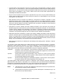
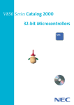
The Ravin-E read and write timing diagrams are depicted in Figure 2-1 and Figure 2-2 respectively. For
reading data from Ravin-E, the CPU must apply the addresses, the byte enable signals and chip select.
In response to chip select, Ravin-E pulls the RDY signal low, to indicate that the data is not yet available. The CPU must then activate RD to request a data read. After the requested data is available,
Ravin-E releases the RDY signal so that the CPU can finish its bus cycle.
Figure 2-1:
Ravin-E read timing
CS
A23 to A2
BE3 to BE0
AD31 to AD0
RD
RDY
[1]
10
[2]
[3]
[4]
Application Note S17194EE1V0AN00
Chapter 2
Hardware Description
A write cycle is very similar to a read cycle. The Ravin-E data bus is switched to input and data is provided by the CPU. Again, when the RDY signal is released, the CPU can finish its bus write cycle.
Figure 2-2:
Ravin-E write timing
CS
A23 to A2
BE3 to BE0
AD31 to AD0
WR
RDY
[1]
[2]
[3]
[4]
2.2 V850E/ME2 Bus Interface
The V850E/ME2 has an external bus interface, which supports accesses to SRAM/ROM/Flash and to
SDRAM. These memory access methods share the same address and data bus, but they use different
control signals. For SDRAM accesses, the address lines carry the multiplexed row and column address
signals.
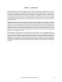
The principle read and write timings of the V850E/ME2 for SRAM accesses are depicted in Figure 2-3
and Figure 2-4. It is apparent that the V850E/ME2 timing is a synchronous timing, in which all bus activity is referenced to a rising or falling edge of the BUSCLK output. A basic and maximum speed SRAM
bus cycle consists of the T1 and the T2 state. The addresses and the chip select signal become valid
after the rising edge of T1. The RD or WR output is activated with the T1 falling edge and T2 is used for
data transfer. At the end of T2, i.e. with the rising clock edge of the subsequent state, the data transfer
is finished and the control signals are returned to inactive.
Four control signals indicate which portion of the data bus conveys valid data. If A is a word address,
then LLBE indicates valid data at A+0, LUBE at A+1, ULBE at A+2 and UUBE applies for A+3. Note
that the xxBE signals are shared with the xxWR signals. Ravin-E requires xxBE functionality, because
the enable signals must be stable while RD or WR are active. As this is not the default after reset, the
PFCCT register must be set to 0x0f during initialization to allow Ravin-E accesses.
The basic bus access can be extended in several ways. The address setup time is extended by inserting up to three address wait states (TASW) before the T1 bus state. Up to seven wait states can be
automatically inserted between the T1 and the T2 state. Further wait states are generated, as long as
the WAIT input is pulled low and up to three idle states (TI) can be inserted at the end of the bus cycle.
Application Note S17194EE1V0AN00
11
Chapter 2
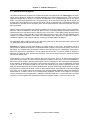
Figure 2-3:
Hardware Description
V850E/ME2 principle SRAM read timing
(a) When read (without speculative read, address set up wait, idle state insertion)
Note 1
TASW
T0
T2
T1
BUSCLK (output)
A0 to A25 (output)
Address
BCYST (output)
CS0 to CS7 (output)
RD (output)
Note 2 (output)
Da ta
D0 to D31 (input)
WAIT (input)
Notes: 1. State (T0) inserted between bus cycles
2. UUBE, ULBE, LUBE, LLBE
Remarks: 1. The circle O indicates the sampling timing.
2. The broken lines indicate the high-impedance state.
12
Application Note S17194EE1V0AN00
TI
T0
Note 1
Chapter 2
Figure 2-4:
Hardware Description
V850E/ME2 principle SRAM write timing
(a) When written (address setup wait, idle state insertion)
Note 1
T0
TASW
T2
T1
TI
BUSCLK (output)
A0 to A25 (output)
Address
BCYST (output)
CS0 to CS7 (output)
WR (output)
Note 2 (output)
Da ta
D0 to D31 (output)
WAIT (input)
Notes: 1. State (T0) inserted between bus cycles
2. UUBE, ULBE, LUBE, LLBE
Remarks: 1. The circle O indicates the sampling timing.
2. The broken lines indicate the high-impedance state.
Application Note S17194EE1V0AN00
13
Chapter 2
Hardware Description
2.3 Access Time Considerations
As it is the case with probably most electronic designs, the designer may have a certain degree of freedom in the interpretation of the electrical specifications. Many timings have minimum and maximum values specified. These parameter ranges account for the full specified voltage and temperature range.
They also include variations in the manufacturing process and aging of the device. Therefore it is reasonable to assume that the drift of parameters on the same device are correlated to one another. In first
approximation, all subcomponents of the device have the same temperature and operating voltage,
they went through the same manufacturing process and they have the same age. In the following discussion we assume therefore, that the variation of all parameters is the same. While this assumption is
probably not acceptable for safety critical equipment, it is common practice for most designs that have
reduced safety requirements. According to individual taste and risk assessment, one can apply a safety
margin between 0 and 100%. The full safety margin will most likely impact the performance.
The following table lists the most critical parameters for reliable operation of Ravin-E with the V850E/
ME2. An eye must be kept on the other parameters as well, but they are usually uncritical and met
under all conditions.
The V850E/ME2 has different minimum bus clock cycle times. Depending on the bus load capacitance,
19 ns (52.6 MHz) or 14.2 ns (70.4 MHz) are permitted. To keep things simple, the table neglects signal
rise and fall times. For conditions where the timing margin is small, it is advisable to consider these rise
and fall times as well as propagation delays of the PCB traces.
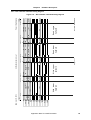
Table 2-1:
Most critical parameters for reliable operation of Ravin-E with the V850E/ME2
Ravin-E
parameter
Ravin-E
V850E/ME2
Busclk T=19 ns
Margin
(n=0)
V850E/ME2
Busclk T=14.2 ns
Margin
(n=0)
V850E/ME2
timing calculation
TAS
min. 5 ns
6.5 + n × 19 ns
1.5 ns
4.1+ n × 14.2 ns
-0.9 ns
tWKH1 + tDKRDL - tDKA+ n × T
TRS/TWS
min. 0 ns
6.5 + n × 19 ns
6.5 ns
4.1+ n × 14.2 ns
4.1 ns
tWKH1 + tDKRDL - tDKA+ n × T
TAH
min. 5 ns
14.5 ns
9.5 ns
12.1 ns
7.1 ns
tSWK + tWKH1 + tHKWRH
TDH
min. 5 ns
0 ns
5 ns
0 ns
5 ns
tHKID - tHKRDH
TAWH
min. 5 ns
8.5 ns
3.5 ns
6.1 ns
1.1 ns
tWKL1 + tHKOD - tHKWRH
TDRCS
min. 0 ns
0 ns
0 ns
0 ns
0 ns
tHKA - tHKRDA
TDD
max. 5 ns
19 ns
14 ns
14.2 ns
9.2 ns
tSWK + T - tSKID
Remark:
14
n is the number of address wait states
Application Note S17194EE1V0AN00
Chapter 2
Hardware Description
The following table is an except from the current V850E/ME2 data sheet and it lists the timing values
that have been used for the above calculations. Note that these values might change in subsequent
revisions, so make always sure to use the latest data sheet.
Table 2-2:
Timing values
Symbol
Min
Max
tWKH1
0.5T - 2 ns
0.5T + 2 ns
tWKL1
0.5T - 2 ns
0.5T + 2 ns
tDKRDL
1 ns
11 ns
tDKA
2 ns
11 ns
tSWK
6 ns
tHKWRH
1 ns
tHKID
2 ns
tHKRDH
2 ns
11 ns
tHKOD
2 ns
11 ns
tHKA
2 ns
11 ns
tHKRDA
2 ns
11 ns
tSKID
6 ns
11 ns
The above analysis of V850E/ME2 and Ravin-E timings shows that both devices can be connected to
each other with sufficient margin. If the V850E/ME2 is operating at the maximum bus speed of
T=14.2 ns, then an address wait state must be inserted for reliable operation.
TDRCS is the RD to CS delay time, which requires that CS must not return to inactive before RD is inactive. That specification might be a concern, because the timing margin is 0 ns. Violation of the TDRCS
specification will, however, not automatically lead to a corrupted bus-cycle. The cycle will simply end
prematurely and the timing parameters that are related to the rising edge of RD, will not be valid anymore. If the host CPU is happy with the reduced data hold time TDH, then this is a perfectly valid RavinE read cycle.
Application Note S17194EE1V0AN00
15
Chapter 2
Hardware Description
2.4 Connecting a V850 or V850E with 16-bit External Bus to Ravin-E
Ravin-E requires a 32-bit bus interface, but most V850 and V850E devices provide only a 16-bit wide
data bus. In some applications one might accept the reduced performance that comes with the 16-bit
interface of a V850. In this chapter we discuss a basic bus extender, which adapts the 16-bit V850 bus
to the 32-bit Ravin-E bus. It should be noted that we have never really built such a circuit and consequently this is just a “thought experiment”. We have written and simulated Verilog code, which can be
easily mapped into a small CPLD. Building the bus extender in discrete logic doesn't seem worthwhile.
The described bus extender has multiple limitations. Obviously it reduces the data throughput to half
the bus frequency, because two bus accesses are required where only one would be necessary in a
pure 32-bit system. A more subtle restriction is the address space. Most V850 devices can only address
external memory of up to 1, 4 or 16 MB. That is more than sufficient to access the Ravin-E Registers,
which occupy only 4 KB, but it may be less than the size of the Ravin-E frame buffer. In such a case the
HostCpuBaseAddr register will have to be updated every time when the required frame buffer address
is out of the current scope. Finally, the described bus extender supports only 32-bit word accesses.
Read-modify-write cycles are required, if smaller entities have to be written. With a little more overhead
it will be possible to access bytes and halfwords, but we restrict this description on the basics. For this
reason, the current implementation does not use the UUBE... LLBE signals.
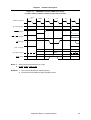
The principle idea of the bus extender is to register the halfword, which cannot currently be transferred.
When doing a word access via a 16-bit bus, the V850 devices transfer the lower 16-bit halfword in the
first bus cycle and the higher 16-bit halfword in the second bus cycle. Therefore the bus extender must
provide two different 16-bit registers, one for read accesses and the other one for write accesses.
For read accesses, i.e. data transfer from Ravin-E to the V850, the first CPU bus cycle performs a 32-bit
Ravin-E read access and with the rising edge of the CPU RD signal, the upper halfword is stored in a
16-bit register, while the lower halfword is directly read from Ravin-E. The subsequent 16-bit read
access transfers the stored upper halfword to the CPU. The write access is very similar, but the lower
halfword must be stored during the first write access, while the second write access actually transfers
the upper halfword from the CPU directly to Ravin-E, while the lower halfword is taken from the register.
As can be seen in the timing diagram on the subsequent page, the bus extender generates chip enable
and byte enable signals also for those V850 cycles, which do not generate Ravin-E cycles. No actual
Ravin-E cycle will be executed, however, because the read and write lines remain inactive. This is a
principle yet acceptable flaw in the concept. The reason are the delayed read and write signals relative
to the chip enable input. Only when read or write gets active, we can decide whether or not a Ravin-E
cycle is to be performed, but then it may be too late to activate the chip and byte enable outputs.
A workaround for that dilemma would be to perform the Ravin-E cycles always when the upper or lower
halfword is accessed, independent of the data transfer direction. Then the bus extender can decide
depending on the A1 address, whether to generate a Ravin-E cycle. The drawback of that solution
would be that word accesses are only performed for reading or writing. The other word access would
have to be replaced by two halfword accesses.
16
Application Note S17194EE1V0AN00
Chapter 2
Hardware Description
2.4.1 Bus extender Verilog code
//
//
//
//
DESIGNER
OBJECT
DATE
REVISION
:Michael Kraemer
:MODULE BusExtender for V850 16-bit bus to Ravin-E 32-bit bus
:07. April 2004
:1.0
// Untested Sample!!! Use with care!
// This module shall interface a 16-bit V850 CPU to a 32-bit Ravin-E
module BusExtender(dv, dr, ncei, nwri, nrdi, a1, nceo, nwro, nrdo, nbeo,
rdyi, nwaito, probe) ;
inout
inout
input
input
input
input
output
output
output
output
input
[15:0] dv ; //
[31:0] dr ; //
ncei ;
//
nwri ;
//
nrdi ;
//
a1 ;
//
nceo ;
//
nwro ;
//
nrdo ;
//
[3:0] nbeo ;//
rdyi ;
//
16-bit V850 data bus
32-bit Ravin-E data bus
chip enable input (active low)
write input (active low)
read input (active low)
A1 from CPU
chip enable output (active low)
chip enable output (active low)
chip enable output (active low)
byte enable output (active low)
ready input from Ravin-E (active high)
output
output
nwaito ;
probe ;
reg
reg
[15:0] dreg ;// data register
rnw ;
// to remember read or write access
wire
wire
cpuread_lower, cpuread_upper, cpuwrite_lower, cpuwrite_upper ;
cpuread, cpuwrite, cclk ;
// wait output to CPU (active low)
//assign defaults
assign cpuwrite = ~ncei & ~nwri ;
assign cpuread = ~ncei & ~nrdi ;
assign cpuread_lower = ~ncei & ~nrdi & ~a1 ;
assign cpuread_upper = ~ncei & ~nrdi & a1 ;
assign cpuwrite_lower = ~ncei & ~nwri & ~a1 ;
assign cpuwrite_upper = ~ncei & ~nwri & a1 ;
assign nceo = ncei ;
assign nwro = ~cpuwrite_upper ;
assign nrdo = ~cpuread_lower ;
assign nbeo[3:0] = {ncei, ncei, ncei, ncei} ;
assign nwaito = ~(~rdyi & (cpuwrite_upper | cpuread_lower)) ;
assign cclk = ncei | ~((~nrdi & ~a1) | (~nwri & ~a1)) ;
assign probe = rnw ;
always @(negedge nwri or negedge nrdi)
begin
if (!nwri) rnw <= 0 ;
if (!nrdi) rnw <= 1 ;
end
always @(posedge cclk)
begin
Application Note S17194EE1V0AN00
17
Chapter 2
Hardware Description
if (rnw)
dreg[15:0] <= dr[31:16] ;
else
dreg[15:0] <= dv[15:0] ;
end
assign dv[15:0] = ~cpuread ? 16'hz :
~a1 ? dr[15:0] :
dreg[15:0] ;
assign dr[31:0] = cpuwrite_upper ? {dv[15:0],dreg[15:0]} : 32'hz ;
endmodule
18
Application Note S17194EE1V0AN00
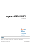
d
dr~result
dv
dv~result
dreg
a1
ncei
nrdi
nwri
rdyi
nbeo
nceo
nrdo
nwaito
nwro
probe
20.0 ns
1111
ZZZZ
ZZZZ
0 ps
Date: April 13, 2004
0000
1111
ZZZZ
ZZZZ
0000
DEA25A5A
DEA2
DEA2
Application Note S17194EE1V0AN00
5A5A
1111
0000
XXXX
5678
1111
ZZZZ
ZZZZ
+220.0 ns +240.0 ns
12345678
12345678
Read lowe r
halfword
ZZZZZZZZ
ZZZZ
Page 1 of 1
Write upper
halfword
ZZZZZZZZ
+140.0 ns +160.0 ns
1111
ZZZZ
Revision: BusExtender
Read upper
halfword
0000
1234
1234
ZZZZZZZZ
ZZZZZZZZ
+300.0 ns
340.0 ns
Project: BusExtender
Figure 2-5:
Write lower
halfword
0000
ZZZZZZZZ
5A5A
5A5A
+60.0 ns +80.0 ns
db/BusExtender-sim.vwf
Chapter 2
Hardware Description
2.4.2 Bus extender simulated timing diagram
Bus extender simulated timing diagram
19
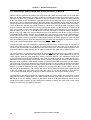
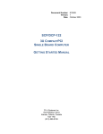
Chapter 3 V850E/ME2 Application Test Board
We have built an application test board with the V850E/ME2 (called ME2-board). Its schematics are
depicted in Chapter 6. This document does not cover the USB, serial interfaces and touch panel interfaces which the ME2-board provides, because they are currently untested. Therefore reuse the respective parts of the schematics with care. The 32-bit bus interface has been made compatible with the
Ravin-E startware board (startWARE-GHS-RavinE), which is not covered by this document. Please
check the startWARE-GHS-RavinE Users Manual (Doc. Nr. TPS-HE-U-6001) for details about that
board.
The major building blocks of the ME2-board are the V850E/ME2 CPU, the Flash/SDRAM memory, the
external bus drivers and the connector as well as the different voltage regulators and the reset generator. These building blocks are briefly described below.
U1 is the V850E/ME2 CPU. An 18.432 MHz crystal is connected to its built-in oscillator, so that an internal operating frequency of 8*18.432 = 147.456 MHz can be achieved. J1 is the CPU N-Wire connector
which enables debugging through any of NEC's V850 emulators. The mode select inputs (MODE[1:0],
JIT[1:0], SSEL[1:0] and PLLSEL) are connected to jumpers, so that any supported configuration can be
chosen. DIP-switch S1 is connected to a few unused port pins and it is not dedicated for a specific purpose.
The 32-bit wide address/data-bus interfaces to the memory block and to the drivers for access to the
Ravin-E board. The address lines are automatically properly multiplexed for access to the SDRAMs.
Two parallel 16-bit wide memories are used for Flash as well as for the SDRAM. We use 256-MBit
memories in either case, so that 64 MB Flash memory and 64 MB SDRAM are available. Due to internal restrictions of the V850E/ME2 address decoding, these sizes may not be completely accessible.
Different voltage regulators are implemented on the ME2-board. Switching regulator U13 generates a
stabilized 5 V master supply voltage VDD50, from which all other voltages are derived by linear regulators. U18 generates VDD33 and U11 generates VDD15 for the core supply. Each of them has shunt resistors in front of its input voltage pin, which reduce the input voltage and dissipate some of the power.
That allows for a reduced heatsink area on the PCB. Heatsinks other than the PCB copper are not
required as long as the load current on VDD33 does not exceed 700 mA and the one on VDD15 doesn't
exceed 250 mA. U2 is a voltage reference for AD-converter. Four LEDs are provided to indicate the
availability of the VDD50, VDD33, VDD15 and AVREF voltages. Amplifying transistors are implemented for
VDD15 and for AVREF. VDD15 is too low to drive an LED and AVREF should not be loaded excessively by
a LED current.
U14 is a reset controller with a manual reset push button PB1. It supervises the VDD33 supply voltage
and can generate an NMI before the reset occurs.
There are a few untested building blocks on the ME2-board. The analog inputs 0..3 are connected to a
discrete external touch-panel interface. Analog inputs 4..7 are available at row-connector J3 and can be
terminated by R2..R5 if unused. The USB function pins are connected to USB-connector U15. The circuit is copied from the V850E/ME2 user manual. The two serial ports of the ME2 device are connected
via RS232-transceiver U20 to two external DSUB-9 male connectors.
20
Application Note S17194EE1V0AN00
Chapter 4 Software Description
4.1 Ravin-E Graphics Library
The Ravin-E graphics library (RGL) was originally written for the NEC MIPS RISC devices VR41xx. It
has been ported to the V850E/ME2 basically just by re-compiling it with the V850E Green Hills tools. An
os_sleep(n) function has been provided, which delays by roughly n milliseconds. It is used for timeouts
and it need not be very precise, but if the CPU core frequency differs much from 150 MHz, it should be
adapted accordingly. os_sleep has been added to rgl_custom.c. This is the file in which also the base
address of the Ravin-E frame buffer (PhysFB) and the Ravin-E registers (PhysReg) must be adapted.
A detailed description of the RGL can be found in the “Ravin-E Graphics Library Manual” in the rgl\doc
directory.
4.2 Display of PNG files
In order to display png files (Portable Network Graphics), we have ported the free PNG Reference
Library libpng (www.libpng.org) to the V850. This library requires the zlib compression library
(www.gzip.org), which has also been ported. These two libraries are documented on their respective
websites. Calls to zlib functions are transparent and the libpng user need not bother too much about
that zlib library. It should be noted, however, that a certain amount of heap space is required for both libpng and zlib. Also the stack size should not be too small, as these functions seem to use it extensively.
They have clearly been written with personal computers in mind and are not optimized for the limited
memory resources of embedded applications. Nevertheless there is a limited number of tuning possibilities by defining certain variables that control compilation of the libraries. See the respective documentation for details.
Application Note S17194EE1V0AN00
21
Chapter 4
Software Description
4.3 Demonstration Programs
Two rather simple demo programs are supplied along with this application note. Datalogger is an application, which displays a simple four channel datalogger grid on the background layer. This is simply a
predefined image that is stored in a PNG-file and extracted once at initialization time into the frame
buffer. Four traces are displayed on the foreground layer, which move from the right side to the left, so
that the older values appear on the left and the newer values on the right side. The displayed values are
generated from pseudo random numbers which are low pass filtered to make them look like real analogue input data.
Display of the trace lines makes use of Ravin-E's feature to move the viewport freely over the virtual display area. When the display line wraps over, Ravin-E does not actually display the image data from the
subsequent line, but the data from the beginning of the current line. This feature permits the impression
of a moving image, without actually copying data within the frame buffer. Only the start address of the
viewport is constantly updated. In the case of the datalogger demo program, the right most column is
updated in addition to the viewport address, as always new data shall be displayed.
The datalogger demo program requires very little CPU performance. Almost all CPU time is spent in the
“os_sleep(20)” delay at the end of function main.
Animation is a demo program which displays a rotating image on the screen. This endless movie is
simply made by displaying a sequence of 60 PNG images cyclically, so that the impression of a movie is
generated. The images were produced by POVRay (www.povray.org) and ThumbsPlus (www.thumbsplus.com) was used to generate a common palette for all of them. A common palette is required to
eliminate the temporal noise, which would otherwise occur due to the asynchronous update of the palette and the display data.
The animation is very simple and it requires the whole CPU time. There is no delay implemented to
slow down the movement. An improvement of speed is possible in many ways. In the current implementation every single image is decompressed again before it is displayed. The most simple improvement
at the expense of RAM space would be to decompress the images only once at initialization time and
merely copy them to the frame buffer at run time. That would not only save the decompression time
itself, but also the assembly time of the individual pixels. Also the actual data transfer would not be performed pixel by pixel but 32-bit wide, i.e. two or four pixels at a time. The performance and the required
CPU time can be further improved by copying the decompressed individual images into Ravin-E's
frame buffer to a location, which is not currently being displayed. Transfer of the image to the screen
location would then be accomplished by a BITBLT command to Ravin-E. For the CPU that is a simple
sequence of a few register write operations and as such it would virtually cost no CPU time at all.
22
Application Note S17194EE1V0AN00
Chapter 5 Performance Measurements
Semiconductor data sheets usually specify timing parameters under well defined conditions. These
parameters are required to design a reliable system, but often they cannot be used to estimate the performance of a real system as they use idealistic assumptions. The system performance is usually limited by many factors, which may sometimes not be calculated or simulated.
Therefore it is useful to measure certain key performance values under real-life conditions. That is what
we have done with the benchmark application, and the results are documented in this chapter.
The benchmarks runs on the V850E/ME2 board with the startWARE-GHS-RavinE board connected to
it. The V850E/ME2 is clocked with 147.456 MHz, the code is executed from the internal instruction
memory and data and stack are located into the internal data memory. The selected screen resolution
is 800 × 600 pixel at 60 Hz frame rate and two display layers are enabled, one with 16 bit per pixel and
the other one with 8 bit per pixel. In this configuration, the screen refresh uses approximately 25% of
the available bandwidth between Ravin-E and its SDRAMs. This is an average bus load calculated for a
whole frame and it includes the sync pulses, during which no data transfer takes place at all. The average data rate during the display of a scan line is about twice as high with short periods of essentially
100% bus load when a burst read is issued to fill the video output pipeline.
5.1 Data transfer rates between V850E/ME2 and Ravin-E frame buffer
This part of the benchmark measures the speed of word read and write transfers between the V850E/
ME2 and the frame buffer. These figures become important when the CPU generates an image, rather
than sending commands to Ravin-E to render it. For the timing of the sequential access, the benchmark
executes a number of read/write accesses to subsequent frame buffer addresses. That is similar to the
case, when a predefined image (e.g. PNG image) is decompressed and transferred to the frame buffer.
Both the CPU and Ravin-E can make use of burst accesses whenever applicable.
For the random access measurements, the CPU accesses words within a predefined address range in
a pseudo random order. In most cases here, burst accesses have no advantage, actually the may
reduce the access times tremendously, because most of the transferred data may be discarded. This
effect can clearly be seen in the case of random read operations.
Table 5-1:
Operation
Random read operations
Time per 32-bit word access [ns]
sequential read
393
sequential write
288
random read
2346
random write
288
The measured values vary slightly between multiple measurements. That is due to the asynchronous
screen refresh that takes place constantly in the background.
Application Note S17194EE1V0AN00
23
Chapter 5
Performance Measurements
5.2 Vector drawing speed
To measure the vector drawing speed, we draw long lines in different angles with the rgl_DrawLine
function, which is setup to use the Ravin-E drawing engine. A total of 50 lines are drawn on the 16-bpp
layer and 49 lines are drawn on the 8-bpp layer. All lines start from the top left to the top right of the
screen and they end at the bottom right to the bottom left. This is just to have different line lengths and
different angles. On the 800 × 600 screen, the line lengths vary between 600 and 1000 pixels. These
are the results of the timing measurements:
Table 5-2:
Vector drawing speed timing measurements
Operation
(600 ~ 1000 pixels)
Average drawing time per line
[µs]
8-bpp Draw Line
47.5
16-bpp Draw Line
27.9
5.3 Filled rectangle drawing speed
The rectangle drawing speed is measured by calling the rgl_DrawBltFillRect function a few hundred
times and then calculating the average execution speed for drawing one rectangle. We have chosen
arbitrarily a size of 30 × 10 pixels and the position of each rectangle on the screen is random. Again we
measured the speed for an 8-bpp and for a 16-bpp layer. Here are the results:
Table 5-3:
24
Filled rectangle drawing speed timing measurements
Operation
(30 × 10 pixels)
Average drawing time per rectangle
[µs]
8-bpp DrawBltFillRect
7.3
16-bpp DrawBltFillRect
9.4
Application Note S17194EE1V0AN00
Application Note S17194EE1V0AN00
FC4
FC3
FC2
VCPU33
VADC33
AVREF
VCPU15
3
4
13
14
166
168
162
150
128
115
100
89
70
53
38
163
V850E/ME2
AVREFM
AVSS
OSCVSS
PLLVSS
UVDD
VDD33
VDD33
VDD33
VDD33
VDD33
VDD33
VDD33
VDD33
OSCVDD
AVDD
AVREFP
VDD15
VDD15
VDD15
VDD15
VDD15
VDD15
PLLVDD
C4
C1
VCPU33
C2
C7
C8
C5
VCPU15
C6
VPLL15
RD/PCT4
WE/WR/PCT5
BCYST/PCT7
LLWRN
LUWRN
ULWRN
UUWRN
83
82
81
80
RXD1
TXD1
P23
P24
P25
UDP
UDM
ANI0
ANI1
ANI2
ANI3
ANI4
ANI5
ANI6
ANI7
160
161
5
6
7
8
9
10
11
12
UCLK
USBCKE
RXD0
TXD0
NMI
149
148
147
146
145
159
155
154
153
152
0.1uF
C10
AVREF
AVREF
0
R5
C13
3.0V
1uFT16
1nF 0.1uF
C11 C12
P1
R4
R3
0
VDD33
2x10K
R6
R7
U22
4
4
6
VIN
U23
4
VDD33
VDD50
8
7
6
5
3
2
C15
10uFT10
SLEEP
REF193
GND
VOUT
U2
NECE
VDD33
VDD33
VDD33
INTP67N
INTP65N
INTPC11
ADTRG
HLDRQN
PCM1
ANI4
ANI6
USBVB
USBMS
P74
BCYSTN
VDD33
FC5
FC6
FC8
C23
A8
A9
A10
A11
A12
A13
A14
A15
A0
A1
A2
A3
A4
A5
A6
A7
C25
C21
C19
R12
0
VCC1
VCC1
2DIR
2OE
2B1
2B2
2B3
2B4
2B5
2B6
2B7
2B8
1DIR
1OE
VCC1
VCC1
2DIR
2OE
2B1
2B2
2B3
2B4
2B5
2B6
2B7
2B8
1DIR
1OE
1B1
1B2
1B3
1B4
1B5
1B6
1B7
1B8
VCC2
VCC2
2A1
2A2
2A3
2A4
2A5
2A6
2A7
2A8
1A1
1A2
1A3
1A4
1A5
1A6
1A7
1A8
VCC2
VCC2
2A1
2A2
2A3
2A4
2A5
2A6
2A7
2A8
1A1
1A2
1A3
1A4
1A5
1A6
1A7
1A8
74LVCH16245APV
VCC1
VCC1
2DIR
2OE
2B1
2B2
2B3
2B4
2B5
2B6
2B7
2B8
1DIR
1OE
U6
1B1
1B2
1B3
1B4
1B5
1B6
1B7
1B8
74LVCH16245APV
VCC1
VCC1
2DIR
2OE
2B1
2B2
2B3
2B4
2B5
2B6
2B7
2B8
1DIR
1OE
U5
1B1
1B2
1B3
1B4
1B5
1B6
1B7
1B8
74LVCH16245APV
VCC2
VCC2
2A1
2A2
2A3
2A4
2A5
2A6
2A7
2A8
U4
1A1
1A2
1A3
1A4
1A5
1A6
1A7
1A8
74LVCH16245APV
VCC2
VCC2
2A1
2A2
2A3
2A4
2A5
2A6
2A7
2A8
31
42
36
35
33
32
30
29
27
26
47
46
44
43
41
40
38
37
31
42
36
35
33
32
30
29
27
26
47
46
44
43
41
40
38
37
7
18
24
25
13
14
16
17
19
20
22
23
1
48
2
3
5
6
8
9
11
12
7
18
24
25
13
14
16
17
19
20
22
23
1
48
These devices contain
bus holder circuits.
7
18
24
25
13
14
16
17
19
20
22
23
0.1uF 0.1uF
C18
CS6N
1
48
BD24
BD25
BD26
BD27
BD28
BD29
BD30
BD31
2
3
5
6
8
9
11
12
7
18
24
25
13
14
16
17
19
20
22
23
1
48
2
3
5
6
8
9
11
12
31
42
36
35
33
32
30
29
27
26
47
46
44
43
41
40
38
37
31
42
36
35
33
32
30
29
27
26
external bus masters
are not supported.
DIR is always A->B
U3
47 1A1
2
1B1
46
3
1B2
44 1A2
5
1A3
1B3
43 1A4
6
1B4
41
8
1B5
40 1A5
9
1B6 11
38 1A6
1A7
1B7
37 1A8
1B8 12
BNRD
BD16
BD17
BD18
BD19
BD20
BD21
BD22
BD23
0.1uF 0.1uF
C20
BD8
BD9
BD10
BD11
BD12
BD13
BD14
BD15
BD0
BD1
BD2
BD3
BD4
BD5
BD6
BD7
0.1uF 0.1uF
C24
A24
A25
LLWRN
LUWRN
ULWRN
UUWRN
NRD
NWE
A16
A17
A18
A19
A20
A21
A22
A23
0.1uF 0.1uF
C22
Notes: CS3 address space
is not cacheable
CS0 and CS2 address
spaces are 7 MB max.
CS1 address space is
64MB-1MB-32kB max.
JP8: 2-3
Flash: CS0 and CS1
SDRAM: CS3
JP8: 1-2
Flash: CS0
SDRAM: CS1 and CS3
VDD50
0.1uF
C14
FC7
Address decoding:
Ravin-E: CS6
C00.0000~F7F.FFFF
KEL8830-026
R1
47K
J1 4x4K7
A1
B1
A2
B2
A3
B3
A4
B4
A5
B5
A6
B6
A7
B7
A8
B8
A9
B9
A10
B10
A11
B11
A12
B12
A13
B13
RN1
8
1
7
2
6
3
4
5
RXD0
RXD1
RESETB
RESET
NMI
RDY
UDM
UDP
UCLK
USBCKE
USBMS
USBVB
TPVNH
TPENAB
ANI[0..3]
VDD33
RXD0
RXD1
RESETB
RESET
NMI
RDY
UDM
UDP
UCLK
USBCKE
USBMS
USBVB
TPVNH
TPENAB
ANI[0..3]
VDD33
CON2X15
J3
1
3
5
7
9
11
13
15
17
19
21
23
25
27
29
2
4
6
8
10
12
14
16
18
20
22
24
26
28
30
NRCE
3 ALVC1G08
5
INTP66N
TOC0
INTPC00
REFRQN
HLDAKN
ANI5
ANI7
RXD1
TXD1
P23
P24
P25
S1
TRCCLK
TRCDATA0
TRCDATA1
TRCDATA2
TRCDATA3
TRCEND
DDI
DCK
DMS
DDO
DRSTN
RESETB
1
2
3
4
VDD33
MEMORY.SCH
TXD0
TXD1
NWE
NRD
NRCE
NECE
LLWRN
LUWRN
ULWRN
UUWRN
3 ALVC1G08
5
4x10K VDD33
RN5
5
4
3
6
2
7
1
8
2
1
JP8 R53
10K
2
1
R54
10K
TXD0
TXD1
NWE
NRD
NRCE
NECE
LLWRN
LUWRN
ULWRN
UUWRN
NOTE: VIN of REF19x must
not exceed 15V, but
must be 1V above VOUT
R2
Termination for unused
analogue inputs.
0
Do not assemble for
used inputs.
ANI0
ANI1
ANI2
ANI3
ANI4
ANI5
ANI6
ANI7
UDP
UDM
P21/RXD1/INTP21
P22/TXD1/INTP22
P23/SCK1/INTP23
P24/SI1/INTP24
P25/SO1/INTP25
P10/UCLK/INTP10
P11/SCK0/INTP11
P12/RXD0/SI0
P13/TXD0/SO0
P20/NMI
TPVNH
TPENAB
RDY
0
WAITN
PCM1
HLDAKN
HLDRQN
REFRQN
ADTRG
DRQB_GDC
DAKB_GDC
INT_GDC
INTPC00
INTPC11
TOC0
INTP65N
INTP66N
INTP67N
34
33
32
31
30
29
25
24
23
22
21
20
19
18
17
USBVB
USBMS
P74
CS0N
CS1N
CS2N
CS3N
CS4N
CS5N
CS6N
CS7N
44
43
42
41
40
37
36
35
NRD
NWE
BCYSTN
SDCASN
SDRASN
BUSCLK
SDCKE
87
86
88
91
79
78
77
A0
A1
A2
A3
A4
A5
A6
A7
A8
A9
A10
A11
A12
A13
A14
A15
A16
A17
A18
A19
A20
A21
A22
A23
A24
A25
76
75
74
73
72
69
68
67
66
65
64
63
62
61
60
59
58
57
52
51
50
49
48
47
46
45
P72/DMARQ2/INTP 176
P73/DMAAK2/INTP 175
P74/TC2/TOC2 174
P75/DMARQ3/INTP 173
P76/DMAAK3/INTP 172
P77/TC3/TOC3 171
WAIT/PCM0
PCM1
HLDAK/PCM2
HLDRQ/PCM3
REFRQ/PCM4
ADTRG/SELFREF/P
INTP50/DMARQ0/P
INTP51/DMAAK0/P
INTP52/TC0/P52
INTPC00/TIC0/DM
INTPC01/DMAAK1/
TOC0/TC1/P55
INTP65/INTPC10/
INTP66/INTPC11/
INTP67/TOC1/P67
CS0/PCS0
CS1/PCS1
CS2/PCS2/IOWR
CS3/PCS3
CS4/PCS4
CS5/PCS5/IORD
CS6/PCS6
CS7/PCS7
VADC33
0.1uF
C9
SDCAS/PCD2
SDRAS/PCD3
BUSCLK/PCD1
SDCKE/PCD0
INTPL0/A0/PAL0
INTPL1/A1/PAL1
A2
A3
A4
A5
A6
A7
A8
A9
A10
A11
A12
A13
A14
A15
A16/PAH0
A17/PAH1
A18/PAH2
A19/PAH3
A20/PAH4
A21/PAH5
A22/PAH6
A23/PAH7
A24/PAH8
A25/PAH9
PCT0/LLWR/LLBE/
PCT1/LUWR/LUBE/
PCT2/ULWR/ULBE/
PCT3/UUWR/UUBE/
partially untested
VDD33
VDD33
VDD15
157
134
102
84
55
26
167
DCK
DMS
DRST
DDI
DDO
TRCCLK
TRCEND
TRCDATA0
TRCDATA1
TRCDATA2
TRCDATA3
0.1uF 0.1uF 0.1uF 0.1uF 0.1uF 0.1uF 0.1uF 0.1uF
C3
8
7
6
5
TRCDATA0
TRCDATA1
TRCDATA2
TRCDATA3
1
2
3
4
RN3
FC1
VPLL15
1 RN2
2
3
4
8
7
6
5
DDI
DDO
TRCCLK
TRCEND
144
143
142
141
140
139
138
137
136
133
132
22p
22p
1 RN4
2
3
4
C16
C17
X2
X1
RESET
MODE0
MODE1
JIT0
JIT1
SSEL0
SSEL1
PLLSEL
D0
D1
D2
D3
D4
D5
D6
D7
D8
D9
D10
D11
D12
D13
D14
D15
D16/PDH0/INTPD0
D17/PDH1/INTPD1
D18/PDH2/INTPD2
D19/PDH3/INTPD3
D20/PDH4/INTPD4
D21/PDH5/INTPD5
D22/PDH6/INTPD6
D23/PDH7/INTPD7
D24/PDH8/INTPD8
D25/PDH9/INTPD9
D26/PDH10/INTPD
D27/PDH11/INTPD
D28/PDH12/INTPD
D29/PDH13/INTPD
D30/PDH14/INTPD
D31/PDH15/INTPD
U1
SDCASN
SDRASN
BUSCLK
SDCKE
A[2..25]
D[0..31]
Memory
D24
D25
D26
D27
D28
D29
D30
D31
D16
D17
D18
D19
D20
D21
D22
D23
D8
D9
D10
D11
D12
D13
D14
D15
D0
D1
D2
D3
D4
D5
D6
D7
R10
0
R8
0
BA24
BA25
BLLWRN
BLUWRN
BULWRN
BUUWRN
BNRD
BNWE
BA16
BA17
BA18
BA19
BA20
BA21
BA22
BA23
BA8
BA9
BA10
BA11
BA12
BA13
BA14
BA15
BA0
BA1
BA2
BA3
BA4
BA5
BA6
BA7
alternative
assembly
CS6N
4K7
R52
4K7
R13
4K7
VDD33
VDD33
R14
DIN96HFABC
1C
1B
1A
2C
2B
2A
3C
3B
3A
4C
4B
4A
5C
5B
5A
6C
6B
6A
7C
7B
7A
8C
8B
8A
9C
9B
9A
10C
10B
10A
11C
11B
11A
12C
12B
12A
13C
13B
13A
14C
14B
14A
15C
15B
15A
16C
16B
16A
17C
17B
17A
18C
18B
18A
19C
19B
19A
20C
20B
20A
21C
21B
21A
22C
22B
22A
23C
23B
23A
24C
24B
24A
25C
25B
25A
26C
26B
26A
27C
27B
27A
28C
28B
28A
29C
29B
29A
30C
30B
30A
31C
31B
31A
32C
32B
32A
This DIN connector uses
a special shape, because
rows a and c are exchanged
on the original Ravin-E
board.
The above row names match
with the usual pinout, but
not with the schematics of
the StartWARE-GHS-RavinE
board.
VSSEL
PCICLK
CPUSEL
INT_GDC
DRQB_GDC
DAKB_GDC
BNWE
BNRD
BA1
BA0
CS6N
BA7
BA6
BA5
BA4
BA3
BA2
WAITN
BA15
BA14
BA13
BA12
BA11
BA10
BA9
BA8
BA23
BA22
BA21
BA20
BA19
BA18
BA17
BA16
RESET
BA25
BA24
BLLWRN
BLUWRN
BULWRN
BUUWRN
BD7
BD6
BD5
BD4
BD3
BD2
BD1
BD0
BD15
BD14
BD13
BD12
BD11
BD10
BD9
BD8
BD23
BD22
BD21
BD20
BD19
BD18
BD17
BD16
BD31
BD30
BD29
BD28
BD27
BD26
BD25
BD24
VDD50 J2
Figure 6-1:
VDD15
28
16
15
2
1
170
169
156
92
93
94
95
96
97
98
99
104
105
106
107
108
109
110
111
112
113
114
117
118
119
120
121
122
123
124
125
126
127
130
131
18.432MHz 164
Y1
165
RESETB
8
7
6
5
JP7
JP6
JP5
JP4
JP3
JP2
JP1
3x4x33
DCK
DMS
DRSTN
VDD33
D0
D1
D2
D3
D4
D5
D6
D7
D8
D9
D10
D11
D12
D13
D14
D15
D16
D17
D18
D19
D20
D21
D22
D23
D24
D25
D26
D27
D28
D29
D30
D31
SDCASN
SDRASN
BUSCLK
SDCKE
A[2..25]
D[0..31]
Chapter 6 Schematics of V850E/ME2 Application Test Board
V850E/ME2 Board
25
26
D[0..31]
A2
A3
A4
A5
A6
A7
A8
A9
A10
A11
A12
A13
A14
A24
A25
P13
P14
VDD15
VDD15
P6
P7
P8
Application Note S17194EE1V0AN00
VPWR=
8.0~20VDC
U12
KSSB62-19
4
3
2
1
1N5818
R24
3
5
Heatsink
6
FB
VIN
OUT
T G
A N O
B D N
U13
LM2596S-ADJ
1
2
4
2
1
P17
P16
P15
3K
UFB=1.230V
UDP
UDM
UCLK
22uFT25L 22uFT25L
C39
C40
P12
VDD33
P5
VDCIN
D2
2
1
P11
VDD33
P4
P9
P10
VDD50
Testpins
C43
C44
23
24
25
26
29
30
31
32
33
34
22
35
36
20
21
C27
C30
C42
10uFT6.3
C45
R23
2.2
R47
3.3
R48
3.3
R49
3.3
FC10
0.1uF
C38
VDD50
VDD33
0.1uF 0.1uF 0.1uF
C29
49
43
9
3
27
14
1
2
4
5
7
8
10
11
13
42
44
45
47
48
50
51
53
C31
VDD33
VDD33
VDD33
VDD33
VDD33I
VDD33I
VDD33I
DQ0
DQ1
DQ2
DQ3
DQ4
DQ5
DQ6
DQ7
DQ8
DQ9
DQ10
DQ11
DQ12
DQ13
DQ14
DQ15
EDS2516APTA
WE
CAS
RAS
CS
CLK
CKE
LDQM
UDQM
A0
A1
A2
A3
A4
A5
A6
A7
A8
A9
A10
A11
A12
BA0
BA1
U8
0.1uF 0.1uF 0.1uF
C26
49
43
9
3
27
14
1
2
4
5
7
8
10
11
13
42
44
45
47
48
50
51
53
C28
VDD33
VDD33
VDD33
VDD33
VDD33I
VDD33I
VDD33I
DQ0
DQ1
DQ2
DQ3
DQ4
DQ5
DQ6
DQ7
DQ8
DQ9
DQ10
DQ11
DQ12
DQ13
DQ14
DQ15
EDS2516APTA
WE
CAS
RAS
CS
CLK
CKE
LDQM
UDQM
A0
A1
A2
A3
A4
A5
A6
A7
A8
A9
A10
A11
A12
BA0
BA1
U7
47uFT16L
10uH
16
17
18
19
38
37
15
39
23
24
25
26
29
30
31
32
33
34
22
35
36
20
21
R16
33
16
17
18
19
38
37
15
39
R15
33
L1
47uFT16L
47uFT16L
D1
1N5822
47uH
L2
C41
10nF
R50
27K
R25
15K
partially untested
NWE
NRCE
NECE
NRD
LLWRN
LUWRN
ULWRN
UUWRN
SDCASN
SDRASN
BUSCLK
SDCKE
USBVB
UDM
UDP
UCLK
USBMS
USBCKE
TPVNH
TPENAB
A2
A3
A4
A5
A6
A7
A8
A9
A10
A11
A12
A13
A14
A24
A25
SAW=01
SSO=10
RAW=10
C37
10uFT6.3
200
1K
R21
U11
LT1117CST
3 I O 2
O 4
G
1 R22
VDD33
700mA max.
VDD33
C36
100uFT4
250mA max.
no heatsink
required
VDD15
C50
100uFT4
U18
LT1117CST-3.3
3 I O 2
O 4
C35
C32
C33
AM29LV256M
33
52
43
29
16
35
37
39
41
44
46
48
50
36
38
40
42
45
47
49
51
VDD33
33
52
43
29
16
35
37
39
41
44
46
48
50
36
38
40
42
45
47
49
51
FC9
0.1uF 0.1uF 0.1uF 0.1uF
C34
RESETB
RDY
0
R20
A2
A3
A4
A5
A6
A7
A8
A9
A10
A11
A12
A13
A14
A15
A16
A17
A18
A19
A20
A21
A22
A23
A24
A25
GND
GND
VCC
VIO
AM29LV256M
CE
OE
WE
BYTE
RESET
RY/BY
U9
A0
DQ0
A1
DQ1
A2
DQ2
A3
DQ3
A4
DQ4
A5
DQ5
A6
DQ6
DQ7
A7
DQ8
A8
DQ9
A9
DQ10
A10
DQ11
A11
DQ12
A12
DQ13
A13
DQ14
A14
DQ15
A15
A16
A17
A18
A19
A20
A21
A22
A23 WP/ACC
4K7
U10
31 A0
DQ0
26 A1
DQ1
25
DQ2
24 A2
A3
DQ3
23 A4
DQ4
22 A5
DQ5
21
DQ6
20 A6
DQ7
10 A7
DQ8
A8
9
DQ9
8 A9
DQ10
7 A10
DQ11
6 A11
DQ12
A12
5
DQ13
4 A13
DQ14
3 A14
DQ15
54 A15
A16
19 A17
18 A18
11 A19
12 A20
15 A21
2 A22
1 A23 WP/ACC
32 CE
VCC
34 OE
VIO
13 WE
53 BYTE
14 RESET GND
17 RY/BY GND
R19
0
32
34
13
53
14
17
NECE
NRD
NWE
R18
31
26
25
24
23
22
21
20
10
9
8
7
6
5
4
3
54
19
18
11
12
15
2
1
A2
A3
A4
A5
A6
A7
A8
A9
A10
A11
A12
A13
A14
A15
A16
A17
A18
A19
A20
A21
A22
A23
A24
A25
Heatsink
G
1
10uFT6.3
C49
D16
D17
D18
D19
D20
D21
D22
D23
D24
D25
D26
D27
D28
D29
D30
D31
D0
D1
D2
D3
D4
D5
D6
D7
D8
D9
D10
D11
D12
D13
D14
D15
CPU
RESET
VDD33
D16
D17
D18
D19
D20
D21
D22
D23
D24
D25
D26
D27
D28
D29
D30
D31
R17
3K3
D0
D1
D2
D3
D4
D5
D6
D7
D8
D9
D10
D11
D12
D13
D14
D15
PB1
R27
33K
VDD33
R28
3K3
R26
4K7
1
4
10n
C46
1
2
4
R46
22K
R45
10K
200ms delay
8
7
5
3
3
10K
R29
U15
VBUS
DD+
ID
GND
5
100K
R36
RESET
RESETB
NMI
2.2uFT20
TXD0
TXD1
RXD0
RXD1
C57
2.2uFT20
C56
VDD33
Q7
BC817-25
D4
D5
C52
VDD33
6
C53
1
4
2
4
8
10
12
C59
2.2uFT20
C60
9
13
11
9
13
12
10
VCC
OE
GND
48 MHz
OUT
R35
0
U19
4
1
2
1
4
10
12
FC11
5
9
4
8
3
7
2
6
1
5
9
4
8
3
7
2
6
1
U17F
74LVC04
1
4
U17E
74LVC04
0.1uF
C48
8
U17D
74LVC04
1
4
U16D
74LVC32
1
4
U16C
74LVC32
1
4
8
VDD50
DSUB9HM
DSUB9HM
P3
P2
11
AVREF
unused gates
2.2uFT20
U21F
74LVC04
1
4
U21E
74LVC04
1
4
U21D
74LVC04
1
4
U21B
74LVC04
1
4
U21A
74LVC04
1
4
Touch Panel
FC12
set RTS and DTR to active
5
3
U21C R51
10K
74LVC04
VDD33
level
shift
VDD33
USBCKE
UPD4721GS
13
11
9
3
1
Q4
BC817-25
VDD33
20
19
18
17
16
15
14
13
12
11
0.1uF
J4
1
2
3
4
C55
10uFT6.3
C54
upper vert.
left hor.
lower vert.
right hor.
Q2
BC807-25
horizontal
U20
VDD
C4+
C1+
GND
VCC
C4C1VSS
STBYC5+
VCHA
C5DOUT1
DIN1
DOUT2
DIN2
RIN1
ROUT1
RIN2
ROUT2
0.1uF 0.1uF 0.1uF
C51
UCLK
TXD0
TXD1
RXD0
RXD1
1
2
3
4
5
6
7
8
9
10
D6
VDD50
VDD33
C58
2.2uFT20
VDD15
R42
330
VDD50
VDD33
6
R41
150
VDD33
AVREF
VDD33
R44
150
D3
1
4
R40
15K
Q5
BC817-25
Q3
BC807-25
R39
15K
U17C
74LVC04
USB-MINI-B
1
2
3
4
5
R38
15K
6
UDM
UDP
4
ANI0
ANI1
ANI2
ANI3
74LVC04
3 U17B
R37
15K
vertical
R43
150
VDD33
R34
22K
R33
10K
R32
1K5
Q1
BC807-25
VDD33
U16B
74LVC32
1
4
14
VDD33
Q6
BC817-25
0.1uF
C47
USBVB
RESET
RESET
PFO
GND
MAX708T
MR
U14
VCC
PFI
AVREF
VDD15
R31
USBMS
4K7
5
TPENAB
R30
10K
4
TPVNH
1
U17A
14
74LVC04
2
1
2
U16A
74LVC32
Figure 6-2:
NWE
NRCE
NECE
NRD
LLWRN
LUWRN
ULWRN
UUWRN
SDCASN
SDRASN
BUSCLK
SDCKE
USBVB
UDM
UDP
UCLK
USBMS
USBCKE
TPVNH
TPENAB
ANI[0..3]
NMI
RESET
RESETB
RDY
ANI[0..3]
NMI
RESET
RESETB
RDY
A[2..25]
Chapter 6
Schematics of V850E/ME2 Application Test Board
SDRAM /Flash Memory, Power, USB, Reset
Facsimile Message
From:
Name
Company
Tel.
Although NEC has taken all possible steps
to ensure that the documentation supplied
to our customers is complete, bug free
and up-to-date, we readily accept that
errors may occur. Despite all the care and
precautions we've taken, you may
encounter problems in the documentation.
Please complete this form whenever
you'd like to report errors or suggest
improvements to us.
FAX
Address
Thank you for your kind support.
North America
Hong Kong, Philippines, Oceania
NEC Electronics America Inc.
NEC Electronics Hong Kong Ltd.
Corporate Communications Dept. Fax: +852-2886-9022/9044
Fax: 1-800-729-9288
1-408-588-6130
Korea
Europe
NEC Electronics Hong Kong Ltd.
NEC Electronics (Europe) GmbH
Seoul Branch
Market Communication Dept.
Fax: 02-528-4411
Fax: +49(0)-211-6503-1344
Asian Nations except Philippines
NEC Electronics Singapore Pte. Ltd.
Fax: +65-6250-3583
Japan
NEC Semiconductor Technical Hotline
Fax: +81- 44-435-9608
Taiwan
NEC Electronics Taiwan Ltd.
Fax: 02-2719-5951
I would like to report the following error/make the following suggestion:
Document title:
Document number:
Page number:
If possible, please fax the referenced page or drawing.
Document Rating
Excellent
Good
Acceptable
Poor
Clarity
Technical Accuracy
Organization
CS 99.1
[MEMO]