1
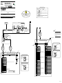
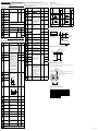
■ How to Install
3. How to Install
User’s
Manual
Models UM351 / UM331
Digital Indicator with Alarms
with Active Color PV Display
User’s Manual Installation
IM 05F01D12-01E
3rd Edition: Sep 30, 2004
This manual describes installation, wiring, and other tasks required to make the indicator ready for operation.
Contents
NOTE
CAUTION
To install the indicator, select a location where:
(1) no one may accidentally touch the terminals,
(2) mechanical vibrations are minimal,
(3) corrosive gas is minimal,
(4) temperature can be maintained at about 23°C and the fluctuation is minimal,
(5) no direct radiant heat is present,
(6) no magnetic disturbances are caused,
(7) no wind blows against the terminal board (reference junction compensation
element),
(8) no water is splashed,
(9) no flammable materials are around,
Turn off the power to the indicator before installing it on the panel because there is a possibility of electric shock.
150mm
150mm
150mm
NOTE
Thank you for purchasing the UM351/UM331 digital indicator with alarms.
The indicator is shipped from the factory with 4 hardcopy user’s manuals (A2 and A3 size). The 3 user’s manuals in hardcopy
format describe the operating procedures required for basic use.
It is recommended that you refer to these user’s manuals to understand [1] installation, [2] initial settings, and [3] operating
procedures of the indicator.
Installation
Basic operation
Initial Settings
Operating
procedures
and troubleshooting
Operations
Small bracket
CAUTION
Install the indicator at an angle within 30° from horizontal with
the front panel facing upward. Do not install it facing downward. The position of right and left sides should be horizontal.
Front panel
of indicator
Must not
exceed 30
Rear of
indicator
30
Description
Recommended
tightening torque
:0.4N m
4. How to Connect Wires
● Installation Position
1) Before carrying out wiring, turn off the power to the indicator and check that the cables to be connected are not
alive with a tester or the like because there is a possibility of electric shock.
2) For the protection and safe use of the indicator, be sure to place a circuit breaker (conforms with IEC60947,
5A, 100V or 220V AC) near the indicator where the breaker can easily be operated. In addition, be sure to
indicated that it is the instrument to cut the power supply of the indicator.
3) Wiring must be carried out by personnel who have basic electrical knowledge and practical experience.
Describes the tasks (installation, wiring, and others) required A2-size paper
to make the indicator ready for operations.
(Front and back)
Describes examples of setting PV input types, and alarm
types. Making settings described herein allows you to carry
out basic monitoring.
Describes examples of setting alarm setpoints, as well as
key operation necessary to run the indicator
A2-size paper
(Front)
Contains the parameter map used as a guideline for setting
parameters and lists of parameters for recording user settings.
A2-size paper
(Front and back)
(Back)
■ External Dimensions and Panel Cutout Dimensions
UM351
Unit: mm
11
Large bracket
100
112
91.8
96
1. Safety Precautions
1) Provide power from a single-phase instrument power supply. If there is a lot of noise in the power line, insert an
insulating transformer into the primary side of the line and use a line filter (recommended part: ZAC2205-00U
from TDK) on the secondary side.
As a countermeasures against noise, do not place the primary and secondary power cables close to each other.
2) For thermocouple input, use shielded compensating lead wires for wiring. For RTD input, use shielded wires
that have low conductor resistance and cause no significant differences in resistance between the three wires.
The cables to be used for wiring, terminal specifications, and recommended parts are as shown below.
3) Alarm output relays have a life of 100,000 times that of the resistance load, use auxiliary relays to turn on/off
a load.
4) The use of inductance (L) loads such as auxiliary relays, motors and solenoid valves causes malfunction or
relay failure; always insert a CR filter for use with alternating current or a diode for use with direct current, as
a spark-removal surge suppression circuit, into the line in parallel with the load.
5) When there is possibility of being struck by external lightening surge, use the arrester to protect the instrument.
The following symbol is indicated on the indicator to ensure safe use.
■ For DC Relay Wiring
CAUTION
Small bracket
1 to 10 mm (Panel thickness)
This symbol on the indicator indicates that the operator must refer to an explanation in the user’s manual in order to
avoid the risk of injury or death of personnel or damage to the instrument. The manual describes how the operator
should exercise special care to avoid electric shock or other dangers that may result in injury or loss of life.
General installation
UM351/UM331
[(N-1)96+92]
■ For AC Relay Wiring
External DC power supply
+0.8
0
+0.8
0
Relay
(Use one with a relay coil rating
less than the UM’s contact rating.)
145 min.
(53)
"N" stands for the number of indicators to be
installed.
However, the measured value applies if N 5.
IMPORTANT
92
Draws attention to information that is essential for understanding the operation and/or features of the indicator.
+0.8
0
Diode
(Mount it directly
to the relay coil
terminal (socket).)
UM’s contact
92
Indicates that operating the hardware or software in a particular manner may damage it or result in a system failure.
92
+0.8
0
Purpose
Unit: mm
UM331
Shielded compensating lead wires, JIS C 1610,
(See Yokogawa Electric's GS 6B1U1-E.)
Small bracket
91.8
Optional functions
-
-
Shielded wires (three conductors), UL2482 (Hitachi Cable)
Other signals
Shielded wires
● Recommended Terminal Lugs
96
Applicable wire size
Tightening torque
0.3 to 1.65 mm2
0.8 N·m or less
7 mm or less
or
1 to 10 mm (Panel thickness)
● Terminal Covers(Optional parts)
Target Model
Part Number
Sales Unit
General installation
UM351
T9115YD
1
145 min.
UM331
T9115YE
1
Digital indicator with alarms (of ordered model): ......................................... 1
Brackets (mounting hardware): ...................................................................... 1 pair
Unit label: ....................................................................................................... 1
User’s Manuals: .............................................................................................. 3 (A2 size)
User’s Manuals “Setting/Explanation of Active Color PV Display”: ............ 1 (A3 size)
User’s Manual (Reference) (CD-ROM Version)
(only for indicators with optional communication functions): ....................... 1
• Purpose: Alarm output, FAIL output, and others
• Number of outputs: 4 (Max).
• Relay contact rating for Alarm 1 to 3: 240 V AC, 1 A, or 30 V
DC, 1 A ; 1a (FAIL output ; 1b)
• Relay contact rating for Alarm 4: 250 V AC, 3 A, or 30 V DC, 3
A (resistance load) 3 terminals (NC, NO, Common); 1c
CAUTION
70 min.
(25)
45
+0.6
0
92
+0.8
0
(53)
1. Before attaching the terminal cover, bend the side with
the groove inward as shown in Fig. A. Be careful not to
bend it backwards. This not only marks it harder to
attach the cover but will also weaken its hold.
2. Fit the holes on the top and bottom (or left and right) of
the terminal cover the projections on the brackets (Fig.
B) and lock in place. The figure right shows the
attachment of a terminal cover to UM indicator.
Power supply: Rated voltage of 100 to 240 V AC (10%), 50/60 Hz
Power consumption: Max. 20 VA (8.0 W max.)
Internal fuse rating: 250 V AC, 1.6A time-lug fuse
Data backup: Non-volatile memory (can be written to up to
100,000 times)
• Withstanding voltage
- Between primary terminals* and secondary terminals**:
At least 1500 V AC for 1 minute
- Between primary terminals* and grounding terminal:
At least 1500 V AC for 1 minute
- Between grounding terminal and secondary terminals**:
At least 1500 V AC for 1 minute
- Between secondary terminals**:
At least 500 V AC for 1 minute
* Primary terminals indicate power terminals and relay
output terminals
** Secondary terminals indicate analog I/O signal, and
contact input terminals
• Insulation resistance: 20 M or more at 500 V DC between
power terminals and grounding terminal
• Grounding: Class D grounding (grounding resistance of 100 or less)
• PV input terminals: Isolated from other input/output terminals.
Not isolated from internal circuit.
• 15 V DC loop power supply terminals: Not isolated from 4-20
mA analog output. Isolated from other input/output
terminals and internal circuit.
• 24 V DC loop power supply terminals: Isolated from 4-20 mA
analog output terminals, other input/output terminals and
internal circuit.
• 4-20 mA analog output terminals (for retransmission): Not
isolated from 15 V DC loop power supply. Isolated from
other input/output terminals and internal circuit.
• Contact input terminals: Not isolated from communication
terminals. Isolated from other input/output terminals and
internal circuit.
• Relay contact output terminals: Not isolated between relay
contact output terminals. Isolated from other input/output
terminals and internal circuit.
• RS-485 communication terminals: Not isolated from contact
input terminals. Isolated from other input/output terminals
and internal circuit.
• Power terminals: Isolated from other input/output terminals and
internal circuit.
• Grounding terminals: Isolated from other input/output terminals
and internal circuit.
Environmental Conditions
Safety and EMC Standards
Check that the following items are provided:
•
•
•
•
•
•
Contact Inputs
• Purpose: Resetting of PV peak and bottom values
• Number of inputs: 1
• Input type: Non-voltage contact or transistor open collector input
• Input contact rating: 12 V DC, 10 mA or more
• On/off determination: For non-voltage contact input, contact
resistance of 1 k or less is determined as “on” and contact
resistance of 20 k or more as “off.”
For transistor open collector input, input voltage of 2 V or
less is determined as “on” and leakage current must not
exceed 100 A when “off.”
• Minimum status detection hold time: About 1 second
• Safety: Compliant with IEC/EN61010-1: 2001, approved by
CSA1010, approved by UL508.
Installation category : CAT. II (IEC/EN61010, CSA1010)
Pollution degree : 2 (IEC/EN61010, CSA1010)
Measurement category : I (CAT. I : IEC/EN61010)
Rated measurement input voltage : 10V DC max.(across
terminals), 300V AC max.(across ground)
Rated transient overvoltage : 1500V (Note)
Note : It is a value on the safety standard which is assumed
by IEC/EN61010-1 in measurement category I, and is not
the value which guarantees an apparatus performance.
11
Front of indicator
Standard type with three alarms
Standard type with three alarms (with 24V DC loop power supply)
None
With communication and additional alarm-4
With additional alarm-4
•
•
•
•
Outputs the PV value.
Either the retransmission output or the loop power supply can be
used with terminals 16 - 17 .
Number of outputs: 1 (terminals 16 - 17 )
Output signal: 4-20 mA DC
Load resistance: 600 or less
Output accuracy: 0.3% of span under standard operating
conditions (23 2C, 55 10% RH, power frequency of
50/60 Hz)
• PV display:
4-digit, 7-segment green or red LED display,
character height of 20 mm (for both UM351 and UM331)
• Setpoint display: 4-digit, 7-segment, red LEDs, character height
of 9.3 mm (for both UM351 and UM331)
• Status indicating lamps: LEDs
3.7mm
Power Supply Specifications
•
•
•
•
Signal Isolations
Retransmission Output
Display Specifications
7 mm or less
100
48
Description
Digital indicator with Alarms (provided with retransmission output and 15
V DC loop power supply as standard)
0
1
2
X-
Small bracket
Before using the indicator, check that the model and suffix codes match your order.
-0
-3
Power is supplied to a two-wire transmitter.
(15 V DC: terminals 16 - 17 ; 24 V DC: terminals 21 - 22 )
A resistor (10 to 250 ) connected between the indicator
and transmitter converts a current signal into a voltage
signal, which is then read via the PV input terminal .
Supply voltage: 14.5 to 18.0 V DC, max. 21 mA (provided
with a protection circuit against a field short-circuit); 21.6
to 28.0 V DC, max. 30 mA (only for models with 24 V DC
loop power supply)
0 to 40C if the 24V DC loop power supply of Model
UM331 is used
Contact Outputs
RTD
3.7mm
Type
Loop Power Supply
112
(1) In order to protect the product and the system controlled by it against damage and ensure its safe use, make certain that
all of the instructions and precautions relating to safety contained in this document are strictly adhered to. Yokogawa
does not guarantee safety if products are not handled according to these instructions.
(2) Modification of the product is strictly prohibited.
UM331
CR filter
(Mount it directly
to the relay coil
terminal (socket).)
Name and Manufacturer
(25)
■ Regarding Protection, Safety, and Prohibition Against Unauthorized Modification
Suffix Code
Relay
(Use one with a relay coil
rating less than the UM’s
contact rating.)
Power supply, grounding, relay contact outputs 600 V PVC insulated wires, JIS C 3307, 0.9 to 2.0 mm2
■ Exemption from Responsibility
2. Model and Suffix Codes
UM’s contact
● Cable Specifications and Recommended Cables
Thermocouple
Make sure that all of the precautions are strictly adhered to. Yokogawa Electric Corporation assumes no liability for any
damage resulting from use of the instrument in contradiction to the precautions.
Also, Yokogawa Electric Corporation assumes no liability to any party for any loss or damage, direct or indirect, caused
by the use or any unpredictable defect of the instrument.
External AC power supply
R
R
The following symbols are used in the hardcopy user’s manuals.
NOTE
UM351/UM331
Relay
Side-by-side close installation
117 min.
Model
Construction, Installation, and Wiring
• Construction: Only the front panel is dust-proof and drip-proof
(protection class IP55)
For side-by-side close installation the indicator loses its
dust-proof and drip-proof protection.
• Material: ABS resin and polycarbonate
• Case color: Black
• Weight: About 1 kg or less
• Dimensions:
UM351 96 (W) 96 (H) 100 (depth from panel face)
mm
UM331 96(W) 48 (H) 100 (depth from panel face)
mm
• Installation: Panel-mounting type. With top and bottom (or right
and left) mounting hardware (1 each)
• Panel cutout dimensions:
UM351 92+0.8
(W) 92+0.8
(H) mm
0
0
UM331 92+0.6
(W) 45+0.8
(H) mm
0
0
• Installation position: Up to 30° upward facing
(not designed for facing downward)
• Wiring: M3.5 screw terminals (for signal wiring and power/
ground wiring as well)
NOTE
Basic operation of
Setting / explanation Describes the setting/explanation of Active Color PV Display. A3-size paper,
Active Color PV Display
back and front
of Active Color PV Display
UM351
PV Input Signals
• Number of inputs: 1 (terminals 11 - 12 - 13 )
• Input type: Universal input system. The input type can be
selected with the software.
• Sampling period: 250 ms
• Burnout detection: Functions at TC, RTD, standard signal
(0.4 to 2 V or 1 to 5 V)
Upscale, downscale, and off can be specified.
For standard signal, burnout is determined to have occurred
if it is 0.1 V or less.
• Input bias current: 0.05 A (for TC or RTD b-terminal)
• Measurement current (RTD): About 0.13 mA
• Input resistance: 1 M or more for thermocouple or mV input
About 1 M for DC voltage input
• Allowable signal source resistance: 250 or less for
thermocouple or mV input
Effects of signal source resistance: 0.1 V/ or less
2 k or less for DC voltage input
Effects of signal source resistance: About 0.01%/100 • Allowable wiring resistance: for RTD input
Maximum 150 /wire: Conductor resistance between three
wires should be equal
However, 10 /wire for a maximum range of -150.0 to
150.0C.
Wire resistance effect: 0.1C /10 • Allowable input voltage: 10 V DC for thermocouple, mV, or
RTD input
20 V DC for DC voltage input
• Noise rejection ratio: 40 dB (50/60 Hz or more in normal mode
120 dB (50/60 Hz) or more in common mode
• Reference junction compensation error: 1.0C (15 to 35C)
1.5C (0 to 15C, 35 to 50C)
• Applicable standards: JIS, IEC, DIN (ITS-90) for thermocouples
and RTD
Media
96
Brief operation
Parameters
and setpoint recording
Insert the indicator
into the opening at
the front of the panel.
Note: Right and left mounting for UM331.
■ How to Use the Manuals
Setup
Direction to insert the
indicator
(bottom mounting hardware)
Introduction
Manual Title
(top mounting hardware)
150mm
Never touch the opening at the bottom of the case. It is to be used in the factory at shipping.
Purpose
After opening the mounting hole on the
panel, follow the procedures below to install the indicator:
1. Insert the indicator into the opening
from the front of the panel so that the
terminal board on the rear is at the far
Terminal board
side.
2. Set the brackets in place on the top and
bottom of the indicator as shown in the
figure on the left, then tighten the screws
Insert a screwdriver into the
of the brackets. Take care not to overbrackets to tighten the screws.
tighten them.
Large bracket
Panel
Never place the indicator directly on flammable items or equipment.
If the indicator has to be installed close to flammable items or equipment, be sure to provide shielding panels all
around the indicator, at least 150mm away from every side; the panels should be made of either 1.43mm-thick
metal-plated steel plates or 1.6mm-thick uncoated steel plates.
1. Safety Precautions
2. Model and Suffix Codes
3. How to Install
4. How to Connect Wires
5. Hardware Specifications
6. Terminal Wiring Diagrams
5. Hardware Specifications
• Normal operating conditions:
Ambient temperature: 0 to 50C (40C or less for side-by-side
close installation)
0 to 40C if the 24V DC loop power supply of Model
UM331 is used
Temperature change rate: 10C/h or less
Ambient humidity: 20 to 90% RH (no condensation allowed)
Magnetic field: 400 A/m or less
Continuous vibration at 5 to 14 Hz: Full amplitude of 1.2 mm or
less
Continuous vibration at 14 to 150 Hz: 4.9 m/s2 or less
Short-period vibration: 14.7 m/s2, 15 seconds or less
Shock: 147 m/s2 or less, 11 ms
Installation height: Height above sea level of 2000 m or less
Warm-up time: 30 minutes or more after power on
• Transportation and storage conditions:
Temperature: -25 to 70C
Temperature change rate: 20C/h or less
Humidity: 5 to 95% RH (no condensation allowed)
• Effects of changes in operating conditions
- Effects from changes in ambient temperature:
- On voltage or thermocouple input, 1 V/C or 0.01%
of F.S./C, whichever is larger
- On RTD input, 0.05C /C (ambient temperature) or less
- On analog output, 0.05% of F.S./C or less
- Effects from power supply fluctuation (within rated voltage
range)
- On analog input, 1 V/10 V or 0.01% of F.S. /10 V,
whichever is larger
- On analog output, 0.05% of F.S./ 10 V or less
This equipment has Measurement category I, therefore do not use the equipment for measurements
within measurement categories II, III and IV.
Measurement category
1
Fold the cover in the direction
of the arrow.
Figure A
2
3
4
Note:Right and left mounting for UM331.
Description
CAT.1 For measurements performed
on circuits not directly
connected to MAINS.
CAT.2 For measurements performed
on circuits directly connected
to the low voltage installation.
CAT.3 For measurements performed
in the building installation.
CAT.4 For measurements performed
at the source of the low-voltage
installation.
Fit the cover hold
over the protrusion
on the mounting bracket.
Remarks
Appliances, portable
equipments, etc.
Distribution board,
circuit breaker, etc.
Overhead wire, cable
systems, etc.
Internal Wiring
3
Entrance 4
Cable
2
T
1
Outlet
Figure B
• EMC standards: Complies with EN61326.
The instrument continues to operate at a measuring
accuracy of within 20% of the range during tests.
IM 05F01D12-01E (1)
6. Terminal Wiring Diagrams
NOTE
Do not use unassigned terminals as relay terminals.
■ UM351 Standard Type (Model UM351-䊐䊐)
RS-485 communication
23 SDB(+)
24
PV input
* Wiring can only be carried out
for indicators with communication
functions.
Maximum baud rate: 9600 bps
* Wiring can only be carried out
for indicators with 24 V DC
loop power supply.
24 V DC loop
power supply
SDA(-)
䊏 Receiving 4-20 mA DC Current
Signals with the Indicator
* Not configured at factory before shipment
See Initial Settings User’s Manual ,
for more information.
* When receiving 4-20 mA DC current signals,
set the PV input type to 1-5 V DC (setpoint “41”).
RTD input
TC input
11 A
12 +
25 RDB(+)
Alarm 4 output
26
RDA(-)
27
SG
21 +
22 -
12 +
12 b
250 Ω 4-20mA
13 -
21.6-28.0VDC
(30 mA DC max.)
13 -
13 B
mV/V input
Note: Connecting a 250 Ω resistor to the terminals is
optional.
Model: X010-250-2 (resistor with M3.5 crimp-on
terminal lugs)
Relay contact output
NC
1
NO
2
COM
3
* Wiring can only be carried out for
UM351-ⵧ1 or UM351-ⵧ2.
Contact rating: 250 V AC, 3 A
30 V DC, 3 A (resistance load)
Power supply
CAUTION
Before carrying out wiring, turn off the power to the
indicator and check that cables to be connected are
not alive with a tester or the like because there is
a possibility of electric shock.
Power supply
L
N
8
12 +
1
21
11
2
22
12
3
23
13
4
24
5
25
6
26
16
16 +
7
27
17
17 -
13 -
Retransmission output
* PV retransmission is configured at factory
before shipment.
4-20 mA DC
Load resistance: 600 Ω or less
8
9
9
19
10
10
20
* If 15 V DC loop power supply is used,
retransmission output cannot be used.
15 V DC loop power supply
16 +
Allowable range: 100 to 240 V AC (10%)
(free voltage)
50/60 Hz shared
14.5-18.0VDC
(21 mA DC max.)
17 Alarm output
Alarm 1 output
AL1 6
Alarm 2 output
AL2 5
UM
Contact input
Relay
Alarm 3 output
AL3 4
Common
COM 7
Resets the PV
peak and bottom values
when DI1 is changed
from OFF to ON.
UM
DI1 19
Common
COM 20
Contact
+5V
Transistor contact
DI1
19
COM
Relay contact rating: 240 V AC, 1 A
30 V DC, 1 A (resistance load)
20
Contact rating: 12 V DC, 10 mA or more
■ UM331 Standard Type (Model UM331-䊐䊐)
䊏 Receiving 4-20 mA DC Current
Signals with the Indicator
* When receiving 4-20 mA DC current signals,
set the PV input type to 1-5 V DC (setpoint “41”).
PV input
12 +
250 Ω 4-20mA
* Not configured at factory before shipment
See Initial Settings User’s Manual ,
for more information.
TC input
13 -
RTD input
Retransmission output
11 A
12 +
16 +
12 b
Note: Connecting a 250 Ω resistor to the terminals is
optional.
Model: X010-250-2 (resistor with M3.5 crimp-on
terminal lugs)
4-20 mA DC
13 -
17 -
Load resistance: 600 Ω or less
13 B
mV/V input
* Wiring can only be carried out
for indicators with 24 V DC
loop power supply.
24 V DC loop
power supply
21.6-28.0VDC
(30 mA DC max.)
15 V DC loop power supply
12 +
16 +
13 -
17 -
+ 21
11 12 13
14.5-18.0VDC
(21 mA DC max.)
16 17
3
UM
DI1 19
Common
COM 20
Contact
+5V
Transistor contact
DI1
19
20
Contact rating: 12 V DC, 10 mA or more
RS-485 communication * Wiring can only be carried out
27
23 SDB(+)
Alarm 4 output
COM
Contact input
Resets the PV
peak and bottom values
when DI1 is changed
from OFF to ON.
19 20
- 22
1
Relay contact output * Wiring can only be carried out for
UM331-ⵧ1 or UM331-ⵧ2.
NC
1
2
* If 15 V DC loop power supply is used,
retransmission output cannot be used.
COM
21 22 23 24 25 26
NO
* PV retransmission is configured at factory
before shipment.
2
3
4
5
6
7
8
9
24
10
for indicators with communication
functions.
Maximum baud rate: 9600 bps
SDA(-)
25 RDB(+)
26
RDA(-)
27
SG
Power supply
Contact rating: 250 V AC, 3 A
30 V DC, 3 A (resistance load)
Power supply
Alarm output
Alarm 1 output
L
UM
AL1 6
N
Relay
Alarm 2 output
AL2 5
Alarm 3 output
AL3 4
Common
8
9
10
CAUTION
Before carrying out wiring, turn off the power
to the indicator and check that cables to be
connected are not alive with a tester or the like
because there is a possibility of electric shock.
Allowable range: 100 to 240 V AC (10%)
(free voltage)
50/60 Hz shared
COM 7
Relay contact rating: 240 V AC, 1 A
30 V DC, 1 A (resistance load)
* Wiring can only be carried out for indicators with 24 V DC
loop power supply.
15 V DC Power Supply Wiring to Two-wire Sensor
24 V DC Power Supply Wiring to Two-wire Sensor
12
External
resistor 100
(Note)
Two-wire transmitter
12
External
resistor 250
(Note)
PV input
0.4 to 2.0 V DC signal
13
16
4-20mADC
17
Two-wire transmitter
Loop power
supply
14.5 to
18.0 V DC
Note: Connecting a 100 resistor to the terminals is optional.
Model: X010-100-2 (resistor with M3.5 crimp-on terminal lugs)
PV input
1 to 5 V DC signal
13
21
4-20mADC
22
Loop power
supply
21.6 to
28.0 V DC
Note: Connecting a 250 resistor to the terminals is optional.
Model: X010-250-2 (resistor with M3.5 crimp-on terminal lugs)
IM 05F01D12-01E (2)
Press the
3.
User’s
Manual
key once to register the setpoint.
SET/ENT
Models UM351 / UM331
Digital Indicator with Alarms
with Active Color PV Display
User’s Manual Initial Settings
IM 05F01D12-02E
8.
SET/ENT
Press the
key once to display the parameter
“RL” (minimum value of PV input range).
PV
AL1
2
3
4
AL1
SET/ENT
3rd Edition: Sep 30, 2004
4.
Press the
key once to display the parameter
“UNIT” (PV input unit).
9.
Displays
parameter
“UNIT”.
PV
SET/ENT
2
3
4
AL1
2
3
Press the
or
key to display the required
setpoint. The figure below shows an example of
setting the minimum value of PV input range to
0.0°C.
AL1
2
3
4
Blinks during
change.
SET/ENT
Press the
key once to display the parameter
“RH” (maximum value of PV input range).
10.
Press the
SET/ENT
The following operating procedure describes an example of changing PV input terminal
the setting of K-type thermocouple (-199.9 to 500.0⬚C) to RTD Pt100 Thermocouple/mV/V input.............................. 12 - 13
RTD input .................................................. 11 - 12 - 13
(-199.9 to 500.0⬚C) and a measurement range of 0.0 to 200.0⬚C.
1.
Bring the operating display into view (display
appears at power on).
AL1
2
3
3. Alarm indicator
lamps
3. Alarm indicator
lamps
5.
and
AL1
4. SET/ENT
key
2. Parameter
Setpoint display
PV
2
3
4
Function
Parameter setpoint display Displays the setpoint of a parameter when it is configured.
3.
Alarm indicator lamps
2
3
4.
SET/ENT
key
5.
and
keys
AL1
2
3
AL1
7.
key once to register the setpoint.
SET/ENT
Used to switch or register a parameter. Pressing the key for more than 3 seconds allows you to switch
between the operating display and the menu for operating parameter setting display alternately.
2.
2
3
2
3
Press the
“STUP”.
4
PV
12.
OFF
1
2. Setting PV Input Type (Setting First at Power-on)
K
NOTE
2
3
The indicator displays the operating display when the power is turned on. However, if PV input type has not
key to
been set, “IN” appears. In this case, first use the
display the input range code to use, then press the
key
NOTE
to register it. Then, set the maximum value (RH) and minimum
If the display is as shown on the left,
value (RL) of the PV input range (for voltage input, set the
press the
key to show the
range code for the PV input type you
maximum value (SH) and minimum value (SL) of the PV input
use. Then, register the range code
scale).
setting by pressing the
key.
The indicator is configured to the initial value of each parameter at the factory before shipment.
First check the initial values shown in 2. Lists of Parameters, in Parameters User’s Manual and change
parameter values as necessary.
J
SET/ENT
3
4
5
PV
2
T
6
4
SET/ENT
SET/ENT
•
B
7
S
8
R
Example of Temperature Input
-200°C
Example of Voltage Input
1V
1370°C
2V
4V
Set the actual
read-out
range.
0°C
800°C
Minimum value of
PV input range (RL)
Maximum value of
PV input range (RH)
PV input range
RL
Parameters to be set for temperature input
1. PV input type (IN): Set according to a sensor
2. Maximum value of PV input range (RH): Set the
maximum value of the range to be displayed.
3. Minimum value of PV input range (RL): Set the
minimum value of the range to be displayed.
(input signal)
RH
N
10
E
11
L(DIN)
12
Set the actual
read-out range.
PV input scale
13
U(DIN)
0.0m3/h
50.0m3/h
Minimum value of
PV input scale (SL)
Maximum value of
PV input scale (SH)
14
Parameters to be set for voltage input
1. PV input type (IN): Set according to an input signal
2. Maximum value of PV input range (RH): Set the maximum value of an input signal.
3. Minimum value of PV input range (RL): Set the minimum value of an input signal.
4. Position of PV input decimal point (SDP): Set the position of the decimal point for PV input display.
5. Maximum value of PV input scale (SH): Set the maximum value of the scale to be displayed.
6. Minimum value of PV input scale (SL): Set the minimum value of the scale to be displayed.
W
15
Platinel 2
16
PR20-40
17
W97Re3W75Re25
The following operating procedure describes an example of setting a K-type thermocouple (-199.9°C to 500.0°C) and a
measurement range of 0.0°C to 200.0°C.
1.
Display screen at power-on
The parameter “IN” for setting the PV input type
appears.
Displays
parameter“IN”.
PV
AL1
SET/ENT
2
3
2.
9
Thermocouple
Instrument
input range
Instrument
input range
PV input range
5V
Press the
or
key to display the required
setpoint.
The figure below shows an example of setting a
K-type thermocouple (-199.9 to 500.0°C). See the
Instrument Input Range Codes.
18
30
JPt100
31
RTD
35
Pt100
36
37
PV
Blinks during
change.
AL1
4
SET/ENT
2
3
3
Standard
signal
4
DC voltage
0.4 to 2 V
1 to 5 V
0 to 2 V
0 to 10 V
-10 to 20 mV
0 to 100 mV
40
41
50
51
55
56
4
Press the
or
key to display the required
setpoint. The figure below shows an example of
setting PV low limit alarm.
4
AL1
2
3
4
Blinks during
change.
SET/ENT
2
3
Press the
“STUP”.
key once to display the menu
The PV display in the figure above shows the error
code for input burnout (
) if PV input wiring is
not yet complete. The error code disappears when
you wire the PV input terminals correctly.
2
*
Performance in the standard condition (at 23⫾2⬚C, 55⫾10%RH, and 50/60Hz power frequency.
Note1: The accuracy is ⫾0.3⬚C of instrument range ⫾1 digit for a temperature range from 0⬚C to 100⬚C.
Note2: The accuracy is ⫾0.5⬚C of instrument range ⫾1 digit for a temperature ranges from -100⬚C to 0⬚C and 100⬚C to 200⬚C.
*
To receive a 4-20 mA DC signal, select a standard signal of 1 to 5 V DC and connect it to a 250⍀ resistor. This resistor is optional.
Model: X010-250-2 (resistor with M3.5 crimp-on terminal lugs)
Press the
key once to register the setpoint.
SET/ENT
Display menu
“STUP”.
PV
4
3
AL1
4
2
3
2
3
4
AL1
4.
Press the
“PWD”.
SET/ENT
Press the
“FUNC”.
3
4
You can take the same steps for alarm-2 type (AL2),
alarm-3 type (AL3), and alarm-4 type (AL4) that are
displayed after this.
Press the
“PWD”.
SET/ENT
key once to display the parameter
key once to display the parameter
9.
Blinks during
change.
13.
Press the
SET/ENT
Press the
key for more than 3 seconds.
This returns you to the display shown at power-on
(figure below).
SET/ENT
Displays
parameter
“PWD”.
PV
2
3
PV
4
Displays
parameter
“PWD”.
2
3
Displays
PV.
AL1
2
3
4
key once to register the setpoint.
SET/ENT
SET/ENT
2
SET/ENT
4
SET/ENT
AL1
Instrument
Measurement Accuracy
Input Range
Set the data item PV Input Type "IN" to the OFF option to leave the PV input
type undefined.
-200 to 1370⬚C
-300 to 2500⬚F
-199.9 to 999.9⬚C
0 to 2300⬚F
⫾0.1% of instrument range ⫾1 digit for temperatures
-199.9 to 500.0⬚C
equal to or higher than 0⬚C
-199.9 to 999.9⬚F
⫾0.2% of instrument range ⫾1 digit for temperatures
-199.9 to 999.9⬚C
below 0⬚C
-300 to 2300⬚F
-199.9 to 400.0⬚C
-300 to 750⬚F
0.0 to 400.0⬚C
-199.9 to 750.0⬚F
⫾0.15% of instrument range ⫾1 digit for temperatures
0 to 1800⬚C
equal to or higher than 400⬚C
32 to 3300⬚F
⫾5% of instrument range ⫾1 digit for temperatures
below 400⬚C
0 to 1700⬚C
32 to 3100⬚F
⫾0.15% of instrument range ⫾1 digit
0 to 1700⬚C
32 to 3100⬚F
⫾0.1% of instrument range ⫾1 digit
-200 to 1300⬚C
⫾0.25% of instrument range ⫾1 digit for temperatures
-300 to 2400⬚F
below 0⬚C
-199.9 to 999.9⬚C
-300 to 1800⬚F
-199.9 to 900.0⬚C
⫾0.1% of instrument range ⫾1 digit for temperatures
-300 to 1300⬚F
equal to or higher than 0⬚C
⫾0.2% of instrument range ⫾1 digit for temperatures
-199.9 to 400.0⬚C
below 0⬚C
-300 to 750⬚F
0.0 to 400.0⬚C
-199.9 to 750.0⬚F
0 to 2300⬚C
⫾0.2% of instrument range ⫾1 digit
32 to 4200⬚F
0 to 1390⬚C
⫾0.1% of instrument range ⫾1 digit
32 to 2500⬚F
⫾0.5% of instrument range ⫾1 digit for temperatures
0 to 1900⬚C
equal to or higher than 800⬚C
32 to 3400⬚F
No guarantee of accuracy for temperatures below 800⬚C
0 to 2000⬚C
⫾0.2% of instrument range ⫾1 digit
32 to 3600⬚F
-199.9 to 500.0⬚C
⫾0.1% of instrument range ⫾1 digit (Note1) (Note2)
-199.9 to 999.9⬚F
-150.0 to 150.0⬚C
⫾0.2% of instrument range ⫾1 digit (Note1)
-199.9 to 300.0⬚F
-199.9 to 850.0⬚C
-300 to 1560⬚F
⫾0.1% of instrument range ⫾1 digit (Note1) (Note2)
-199.9 to 500.0⬚C
-199.9 to 999.9⬚F
-150.0 to 150.0⬚C
⫾0.2% of instrument range ⫾1 digit (Note1)
-199.9 to 300.0⬚F
0.400 to 2.000 V
1.000 to 5.000 V
⫾0.1% of instrument range ⫾1 digit (Note)
0.000 to 2.000 V
The read-out range can be scaled between -1999 and
0.00 to 10.00 V
9999.
-10.00 to 20.00 mV
0.0 to 100.0 mV
8.
PV
SET/ENT
Select the unit from the UNIT parameter.
AL1
2
PV
4.
Displays menu
“STUP”.
AL1
■ Instrument Input Range Codes
Unspecified
3
PV
Press the
or
key to display the required
setpoint. The figure below shows an example of
setting the maximum value of PV input range to
200.0°C.
5.
PV
AL1
4
2
3
Press the
“FUNC”.
SET/ENT
SET/ENT
key once to display the menu
See “1. Setting an Alarm Setpoint” in Operations
User’s Manual when setting an alarm setpoint.
4
Displays menu
“FUNC”.
SET/ENT
SET/ENT
Instrument Input
Range Code
2
SET/ENT
PV
3
3.
Displays
parameter
“RH”.
AL1
key once to display the menu
Displays
PV.
5.
Type
7.
Displays menu
“OP.PA”.
PV
PV
Input
AL1
SET/ENT
3.
4
IMPORTANT
•
4
SET/ENT
AL1
The indicator automatically returns to the display at the time of power-on (i.e., Operating display) if no key is
operated for at least one minute.
3
Displays
parameter
“AL1”.
PV
SET/ENT
4
PV
AL1
2
Press the
key for more than 3 seconds to
call up the menu “OP.PA”.
AL1
SET/ENT
2
Press the
key once to display the parameter
“RH” (maximum value of PV input range).
SET/ENT
key for more than 3 seconds. This
returns you to the display shown at power-on (figure
below).
AL1
11.
Displays
menu “OP.PA”.
AL1
SET/ENT
The following explanation of operation for the UM351’s panel, shown in the figure, is the same as that of the UM331’s
panel.
2
SET/ENT
SET/ENT
PV
PV
Used to change numerical values. On setting displays for various parameters, you can change parameters,
setpoint. Pressing the
key decreases a numerical value, while pressing the
key causes it to
increase. You can hold down a key to gradually increase the speed of change.
7
SET/ENT
AL1
Press the
1
7
4
4
SET/ENT
If any of alarms 1 to 4 occurs, the respective alarm indicator lamp (AL1 to AL4) is lit (in orange).
SET/ENT
11. Press the
Blinks during
change.
SET/ENT
• Displays a PV value during operation.
• Displays a parameter symbol when you set a parameter.
• Displays an error code in red if the indicator fails.
2.
SET/ENT
4
SET/ENT
PV
AL1
Name of Part
Process variable (PV)
display
3
keys
4. SET/ENT key
1.
2
Press the
key for more than 3 seconds to
call up the menu “OP.PA”.
SET/ENT
Press the
or
key to display required the
setpoint. The figure below shows an example of
setting the maximum value of PV input range to
200.0°C.
keys
4
Factory-set defaults
)............PV high limit alarm
)............PV low limit alarm
)............PV high limit alarm
- 3 )......PV low limit alarm
Press the
key once to display the parameter
“AL1” (alarm-1 type).
SET/ENT
2.
If the type of input is voltage, also configure the PV
Input Decimal Point Position (SDP), Maximum value
of PV Input Scale (SH), and Minimum value of PV
Input Scale (SL) parameters that are displayed after
this.
6.
5
7
PV
4
1. Process
variable (PV)
display
UM331
2. Parameter
Setpoint
display
and
key once to register the setpoint.
Press the
key once to display the parameter
“UNIT” (PV input unit).
Displays
parameter
PV
“UNIT”.
SET/ENT
SET/ENT
5.
10.
Displays
PV.
AL1
Displays
parameter
“RH”.
PV
UM351
6.
Displays
PV.
PV
AL1
1. Names and Functions of Front Panel Parts
1. Process
variable (PV)
display
Bring the operating display into view (appears at
power-on).
SET/ENT
4
SET/ENT
1. Names and Functions of Front Panel Parts
2. Setting PV Input Type (Setting First at Power-on)
3. Changing PV Input Type
4. Changing Alarm Type
5. Setting Hysteresis in Alarm Setpoint
1.
3. Changing PV Input Type
PV
5.
Alarm-4 (terminal numbers
-
6
PV
SET/ENT
Contents
The following operating procedure describes an example of changing Alarm output terminals
alarm-1 (factory-set value: PV high limit alarm) to PV low limit alarm. Alarm-1 (terminal numbers
When you have changed alarm type, the alarm setpoint will be initial- Alarm-2 (terminal numbers
Alarm-3 (terminal numbers
ized; set the alarm setpoint again.
SET/ENT
SET/ENT
This manual describes examples of setting the types of PV input and alarm. Carrying out settings described herein allows
you to perform basic monitoring. Refer to examples of various settings to understand how to set parameters required. Refer
to “1. Parameter Map” in Parameters User’s Manual for an easy to understand explanation of setting various parameters. If you cannot remember how to carry out an operation during setting, press the
key for more than 3 seconds.
This brings you to the display (operating display) that appears at power-on.
The indicator may automatically initialize the registered operating parameter setpoints if any change is made to the
data item PV Input Type (IN), Maximum Value of PV Input Range (RH), Minimum Value of PV Input Range (RL),
PV Input Decimal Point Position (SDP), Maximum Value of PV Input Scale (SH) or Minimum Value of PV Input
Scale (SL). After a change has been made to any of these data items, be sure to verify the registered operating
parameter setpoints to ensure that they are correct. If any data item has been changed to its default, set it to a
required value.
Displays
parameter
“RL”.
PV
4. Changing Alarm Type
NOTE
key once to display the menu
14.
Press the
key once to display the parameter
“RL” (minimum value of PV input range).
Displays
menu “FUNC”.
PV
AL1
2
3
2
3
4
SET/ENT
PV
4
SET/ENT
Displays
parameter
“RL”.
AL1
2
3
5. Setting Hysteresis in Alarm Setpoint
4
The following operating procedure describes an example of setting a 5.0°C hysteresis level in the alarm setpoint.
SET/ENT
SET/ENT
1.
6.
Press the
key once to display the menu “I/O”.
15.
Press the
or
key to display the required
setpoint. The figure below shows an example of
setting the minimum value of PV input range to
0.0°C.
6.
Press the
key several times to display the
parameter “HY1” (alarm-1 hysteresis).
SET/ENT
Displays
PV.
PV
AL1
Displays
menu “I/O”.
PV
Bring the operating display into view (appears at
power-on).
2
3
4
AL1
2
3
AL1
4
2
3
Press the
key once to display the parameter
“IN” (PV input type).
SET/ENT
16.
Press the
SET/ENT
Blinks during
change.
2.
Press the
key for more than 3 seconds to
call up the menu “OP.PA”.
SET/ENT
key once to register the setpoint.
7.
Press the
setpoint.
or
Displays menu
“OP.PA”.
PV
2
3
2
3
4
AL1
4
AL1
SET/ENT
Press the
or
key to display the required
setpoint. The figure below shows an example of
changing to RTD Pt100 (-199.9 to 500.0°C).
Blinks during
change.
AL1
2
3
17.
2
3
Press the
“STUP”.
Blinks during
change.
SET/ENT
key once to display the menu
SET/ENT
8.
Press the
SET/ENT
AL1
Displays
PV.
PV
AL1
2
3
Display menu
“STUP”.
PV
key once to register the setpoint.
2
3
PV
4
AL1
SET/ENT
2
3
4
SET/ENT
You can take the same steps for alarm-2 hysteresis
(HY2), alarm-3 hysteresis (HY3), and alarm-4
hysteresis (HY4) that are displayed after this.
4
SET/ENT
4.
SET/ENT
4
4
Press the
key for more than 3 seconds.
This returns you to the display shown at power-on
(figure below).
4
SET/ENT
Press the
3
SET/ENT
PV
9.
2
PV
3.
8.
key to display the required
PV
SET/ENT
AL1
4
SET/ENT
AL1
Displays
parameter “IN”.
PV
3
4
SET/ENT
SET/ENT
7.
2
PV
SET/ENT
AL1
Displays
parameter
“HY1”.
PV
key once to register the setpoint.
PV
* If the type of input is voltage, also configure the
PV Input Decimal Point Position (SDP), Maximum
value of PV Input Scale (SH), and Minimum value
of PV Input Scale (SL) parameters that are
displayed after patameter RL.
Press the
“PWD”.
SET/ENT
key once to display the parameter
Displays
parameter
“PWD”.
PV
AL1
AL1
2
3
2
3
9.
Press the
key for more than 3 seconds.
This returns you to the display shown at power-on
(figure below).
SET/ENT
PV
4
Displays
PV.
AL1
2
3
4
4
SET/ENT
SET/ENT
SET/ENT
5.
Press the
“FUNC”.
SET/ENT
key once to display the menu
Displays menu
“FUNC”.
PV
AL1
2
3
4
SET/ENT
IM 05F01D12-02E (1)
2. Troubleshooting
User’s
Manual
Models UM351 / UM331
Digital Indicator with Alarms
with Active Color PV Display
User’s Manual Operations
IM 05F01D12-02E
■ Troubleshooting Flow
If the operating display does not appear after turning on the indicator's power, try to solve the problem by following the
procedure below. If the problem seems to be complex, contact the vendor from which you purchased the instrument.
Is the instrument
defective?
Yes
3rd Edition: Sep 30, 2004
No
Totally
inoperable?
Yes
This manual describes key entries for operating the indicator. If you cannot remember how to carry out an operation during
setting, press the
key for more than 3 seconds. This brings you to the display (operating display) that appears at
power-on.
SET/ENT
No
Is key
operation
faulty?
Yes
Check wiring on the
power supply
terminals.
No
Is display
faulty?
Yes
Check the key lock
setting.
Is
communication
link faulty?
No
Yes
Turn off power, and
then turn it on
again.
Yes
Check the
instrument’s I/O
specifications.
Check the supply
voltage.
Check the
instrument's suffix
code.
No
Check the specifications
of I/O counterpart for
wrong polarity.
No
Contents
No communication
capability.
Normal?
No
1.
2.
Is I/O
signal faulty?
Setting Alarm Setpoints
Troubleshooting
Is
key lock
enabled?
Yes
Correct
errors.
Check the specifications
of communication
counterpart.
Correct?
Yes
Yes
Do not use the instrument genarating strong magnetic field such as radio equipment and the like near the indicator.
This may cause the fluctuation of the PV value.
Ask the vendor for repair.
Check the
communication-related
parameters.
Check
communication wiring.
No
NOTE
Does the code
include a communication
option?
Disable
key lock.
Find the cause.
1. Setting Alarm Setpoints
The following operating procedure describes an example of setting Alarm output terminals
Alarm-1 (terminal numbers
a value of 160.0 in the alarm 1 setpoint parameter. Before setting
Alarm-2 (terminal numbers
the alarm setpoint, check the alarm type. To change the alarm type,
Alarm-3 (terminal numbers
see “4. Changing Alarm Type” in Initial Settings User's
Alarm-4 (terminal numbers
Manual .
Factory-set defaults
- 7 )............PV high limit alarm
- 7 )............PV low limit alarm
- 7 )............PV high limit alarm
- 2 - 3 ).......PV low limit alarm
6
5
4
1
IMPORTANT
Take note of the parameter settings when asking the vendor for repair.
■ Errors at Power On
1.
Bring the operating display into view (display
appears at power on).
4.
Press the
setpoint.
or
AL1
2
3
AL1
4
2
3
4
Blinks during
change.
SET/ENT
Press the
key for more than 3 seconds to call
up the menu “OP.PA”.
SET/ENT
5.
Press the
SET/ENT
Displays menu
“OP.PA”.
PV
AL1
2
3
Description
of error
PV
Control
output
Alarm
output
Retransmission Communioutput
cation
Remedy
PV
SET/ENT
2.
The following table shows errors that may be detected by the fault diagnosis function when the power is turned on.
Error indication
(on PV display unit)
Displays PV.
PV
key to display the required
key once to register the setpoint.
PV
4
Faulty RAM
(E001)
Faulty ROM
(E002)
System data error 0%
PV decimal point blinks.
(E400)
AL1
SET/ENT
(E000)
2
3
Faulty calibration
value
Parameter error
None
0% or less
0% or less
or OFF
Stopped
OFF
0%
Normal action Normal action Normal action Normal action
Normal
(out of
(out of
(out of
(out of
action
accuracy)
accuracy)
accuracy)
accuracy)
0%
Preset value OFF
Faulty
Contact us
for repair.
Check and set
the parameters,
as they have
been set to the
limited values.
0%
4
SET/ENT
■ Possible Errors during Operation
You can take the same steps for alarm-2 setpoint
(A2), alarm-3 setpoint (A3), and alarm-4 setpoint
(A4) that are displayed after this.
3.
Press the
“A1”.
SET/ENT
key once to display the parameter
Displays
parameter
“A1”.
PV
AL1
SET/ENT
2
3
6.
Press the
key for more than 3 seconds.
This returns you to the display shown at power-on
(figure below).
SET/ENT
Displays PV.
PV
4
The following shows possible errors occurring during operations.
Error indication Description
(on PV display of error
unit)
PV
Displays “RJC”
and PV
alternately
RJC error
PV value blinks. EEPROM
error
AL1
2
3
Alarm
output
Retransmis- Commusion output nication
Measured with RJC=OFF Normal
action
Normal
action
Normal
action
Normal
action
Faulty
Contact us for repair.
Normal
action
Normal
action
Normal
action
Normal
action
Faulty
Contact us for repair.
105%
Preset
value
Normal
action
Normal
action
Normal
action
Dependent on the BSL
parameter Up-scale: 105%
Down-scale: -5%
Preset
value
Normal
action
Normal
action
Normal
action
Check wires and
sensor.
Normal
action
Normal
action
Normal
action
Normal
action
Check process.
Normal
action
Normal
action
Normal
action
Normal
action
Check wires and
communication parameters,
and make resetting.
Recovery at normal receipt
Normal action
Control
output
Remedy
4
SET/ENT
(E300)
A/DC error
(B.OUT) PV burnout
error
(OVER) or Excessive PV -5% or 105%
(-OVER) Out of -5 to
105%
SP decimal pont Faulty
blinks (on
communisetpoint display cation line
unit).
Normal action
All indications off Runaway (due None
to defective
power or
noise)
0% or less OFF
or OFF
0% or
less
Stopped
Faulty if power off/on does
not reset start the unit.
Contact us for repair.
All indications off Power off
0%
0%
Stopped
Check for abnormal power.
None
OFF
■ If a Power Failure Occurs during Operation
● Momentary power failures shorter than 20 ms
The indicator is not affected at all and continues normal operation.
● Momentary power failures of 20 ms or longer
• The alarm function of the indicator continues to work normally. (Alarms with the stand-by feature temporarily return to
their stand-by state, however.)
• Setting parameters that have already been configured retain their settings.
IM 05F01D12-02E (2)
User’s
Manual
Models UM351 / UM331
Digital Indicator with Alarms
with Active Color PV Display
User’s Manual Parameters
IM 05F01D12-03E
Basic Key Operation Sequence
3rd Edition: Sep 30, 2004
1. Setting display can be switched (moved) using the
SET/ENT
key.
2. A numerical value is changed by
(1) Using the
This manual contains a parameter map as a guideline for setting parameters, and lists of parameters for recording User
Settings.
?
Contents
key to change a displayed value (decimal point blinking) and
key to register it.
SET/ENT
SET/ENT
3. Pressing the
key on an operating display (for more than 3 seconds) brings you to the
operating parameter setting display.
If you become unsure of key operation during parameter
setting, hold down the
key for more than
3 seconds. This returns you to the display at
power-on (i.e., operating display).
4. Pressing the
key on the operating parameter setting display (for more than 3 seconds)
returns you to the operating display.
SET/ENT
SET/ENT
1. Basic Key Operation Sequence and Parameter Map
2. Lists of Parameters
or
(2) Pressing the
5. Pressing the
key on the setup parameter setting display (for more than 3 seconds)
returns you to the operating display. You cannot return to the operating parameter setting
display from the setup parameter setting display.
SET/ENT
1. Basic Key Operation Sequence and Parameter Map
Power on
Determine PV input type first.
Display example
Display example
PV
No
Yes
Display?
IN = OFF
Blinks during
change.
PV
AL1
2
3
4
AL1
SET/ENT
C
Settings herein are described in “2. Setting PV Input Type
(Setting First at Power-on) ” in Initial Settings User’s Manual .
2
3
PV
4
SET/ENT
AL1
2
3
A
4
or
key to set a numerical
value. See Instrument Input Range Codes
in Initial Settings User’s Manual .
2. Press the
SET/ENT
C
After PV input type (IN), input/output
parameters such as PV input unit (UNIT),
maximum value of PV input range (RH),
and minimum value of PV input range
(RL) will be displayed.
SET/ENT
1. Use the
B
key to register
the value.
NOTE
Changing the registered value of a setup parameter
may cause the registered value of an operating parameter to be initialized automatically. Thus, when
you have changed a setup parameter, always check
that the registered value of the operating parameter
is appropriate. If it is initialized to default, reset it to
the required value.
key
SET/ENT
Press this key for
more than 3 seconds
to move to the
operating
display.
Operating Display
Displays PV
A
PV
AL1
2
3
Displayed first after power on.
Setup Parameter Setting Display
4
SET/ENT
Alarm/Communication
related
Input related
Description of Setup Parameter Menu Display
or
key
SET/ENT
SET/ENT
key
Displays a menu, such as
FUNC or I/O.
key
Menu
SET/ENT
key
SET/ENT
Press this key for more
than 3 seconds to
move to the operating
parameter setting
display.
key
PV color mode
PV input type
(PV INPUT terminals)
Alarm-1 type
PV input unit
AL1
Press this key for
more than 3 seconds
to move to the
operating
display.
Alarm-2 type
Maximum value of PV input range
Alarm-3 type
Minimum value of PV input range
Menu
Alarm-4 type
Operating Parameter Setting Display
or
Description of Operating Parameter Menu Display
key
key
SET/ENT
key
Alarm-1 setpoint
Password input
Displays the
operating
parameter menu
symbol “OP.PA.”
Alarm-3 setpoint
SET/ENT
B
PV bottom value
AL1
2
3
Alarm-3 hysteresis
Presence/absence of PV input
reference junction compensation
Nothing is displayed.
Description of Setup Parameter Setting Display
Displays a parameter.
PV
AL1
2
3
4
Displays a setpoint.
SET/ENT
External RJC setpoint
(displayed when IN=TC)
Alarm-1 delay timer
Selection of
PV input burnout action
Alarm-2 delay timer
Retransmission output type
Alarm-3 delay timer
Maximum value of
retransmission output scale
Alarm-4 delay timer
Description of Operating Parameter Setting Display
Displayed only for UM351-ⵧ1,
UM351-ⵧ2, UM331-ⵧ1, UM331-ⵧ2.
Minimum value of
retransmission output scale
Protocol selection
DI function selection
Baud rate
SELECT display-1 registration
Parity
SELECT display-2 registration
PV
2
3
4
Displays a setpoint.
PV input bias
Stop bit
SET/ENT
Displayed when PCMD
(PV color mode parameter)
= 6 or 7
SET/ENT
Displayed only for UM351-ⵧ1,
UM351-ⵧ2, UM331-ⵧ1, UM331-ⵧ2.
4
key
AL1
To switch the parameter display, press the
4
Nothing is displayed.
Displays a
parameter
symbol.
PV input filter
SET/ENT
Alarm-2 hysteresis
Minimum value of PV input scale
(displayed at voltage input)
Displayed only for UM351-ⵧ1, UM351-ⵧ2, UM331-ⵧ1, UM331-ⵧ2
PV peak value
Low limit for
PV color change
Maximum value of PV input scale
(displayed at voltage input)
Alarm-4 hysteresis
SET/ENT
High limit for
PV color change
3
PV input decimal point position
(displayed at voltage input)
Displayed only for UM351-ⵧ1,
UM351-ⵧ2, UM331-ⵧ1, UM331-ⵧ2.
Alarm-1 hysteresis
PV
(No password is required
when PWD = 0.)
Alarm-2 setpoint
Alarm-4 setpoint
2
SET/ENT
Menu
SET/ENT
PV
Displayed only for indicators
with communication functions
SELECT display-3 registration
Data length
SELECT display-4 registration
Address
Key lock
Minimum response time
Password setting
key.
key
This parameter is not to be set.
SET/ENT
SET/ENT
key
key
IM 05F01D12-03E (1)
2. Lists of Parameters
* Parameters relating to PV should all be set in real numbers.
For example, use temperature values to define alarm setpoints for
temperature input.
Name of Parameter
Alarm 1-setpoint
Setting Range and Description
Initial Value
PV alarm: -100.0 to 100.0% of PV input range
User setting
PV high limit
alarm:
100.0% of
PV input range
PV low limit
alarm:
0.0% of
PV input range
(A1)
Alarm 2-setpoint
(A2)
Alarm 3-setpoint
(A3)
Parameter
Symbol
Name of Parameter
Setting Range and Description
(IN)
PV input type (PV INPUT
terminals)
11 - 12 - 13 terminals
PV input unit
OFF, 1 to 18, 30, 31, 35 to 37, 40, 41, 50, 51, 55, 56
See Instrument Input Range Codes in Initial
Settings User’s Manual .
°C: degree Celsius
°F: Fahrenheit
Max. value of PV input
range
(RH)
Alarm 4-setpoint
Min. value of PV input
range
PV peak value
Displays the maximum value of PV input during operation.
This parameter is not to be set.
PV bottom value
Displays the minimum value of PV input during operation.
This parameter is not to be set.
(RL)
(PEAK)
(SDP)
(BOTM)
PV input filter
OFF, 1 to 120 second
Used when the PV input fluctuates.
OFF
PV input bias
-100.0% to 100.0% of PV input range span
Used to correct the PV input value.
0.0% of PV
input range
span
High limit for
PV color change
When PCMD (PV color mode parameter) = 6 or 7 :
-100.0 to 100.0 % of PV input range
(FL)
(BS)
(SH)
When PCMD = 6 or 7 :
PCCH = 100.0%,
PCCL = 0.0 %
(PCCH)
(SL)
Low limit for
PV color change
(BSL)
(PCCL)
■ Setup Parameters
(RJC)
● Alarm/Communication-related Parameters
Name of Parameter
Initial Value
OFF
Alarm type code
User Setting
Alarm type
“Open/close” shows status of relay contact,
and “lit” and “unlit” shows status of lamp
°C
PV input decimal point
position (displayed
at voltage input)
Set the PV input range, however RL < RH
-Temperature input
Set the range of temperature that is actually indicated.
- Voltage input
Set the range of a voltage signal that is applied.
The scale across which the voltage signal is actually
indicated should be set using the parameters
Maximum Value of PV Input Scale (SH) and Minimum
Value of PV Input Scale (SL).
0 to 3
Set the position of the decimal point of voltagemode PV input.
0: No decimal place
1: One decimal place
2, 3: Two, three decimal places
-1999 to 9999, however SL < SH
Set the read-out scale of voltage-mode PV input.
Max. value of PV input
scale
(displayed at voltage input)
Min. value of PV input
scale
(displayed at voltage input)
Selection of PV input
OFF
burnout action
1: Up scale
2: Down scale
OFF, ON
Presence/absence of
PV input reference
junction compensation
External RJC setpoint
-50.0 to 50.0 ⬚C
-58.0 to 122.0 ⬚F
Contact
closes
if alarm
occurs
No alarm
“Open/close” shows status of relay contact,
and “lit” and “unlit” shows status of lamp
PV high limit
Open (unlit)
De-energized
on PV high limit
Closed (lit)
PV
PV low limit
Hysteresis
1
Alarm setpoint
Closed (lit)
De-energized
on PV low limit
Initial Value
User setting
(PCMD)
Alarm-1 type
(AL1)
Alarm-2 type
(AL2)
Alarm-3 type
(AL3)
Alarm-4 type
(AL4)
0: Fixed in green
1: Fixed in red
2: Link to alarm 1 (Alarm OFF:green, Alarm ON:red)
3: Link to alarm 1 (Alarm OFF:red, Alarm ON:green)
4: Link to alarm 1 and 2 (Alarm OFF:green, Alarm ON:red)
5: Link to alarm 1 and 2 (Alarm ON:red, Alarm OFF:green)
6: PV limit (Within PV range:green, Out of PV range:red)
7: PV limit (Within PV range:red, Out of PV range:green)
1
OFF
1: PV high limit (energized, no stand-by action)
2: PV low limit (energized, no stand-by action)
9: PV high limit (de-energized, no stand-by action) 2
10: PV low limit (de-energized, no stand-by action)
11: PV high limit (energized, stand-by action)
12: PV low limit (energized, stand-by action)
1
19: PV high limit (de-energized, stand-by action)
20: PV low limit (de-energized, stand-by action)
21: Fault diagnosis output
2
Turns on in case of input burnout, A/D
converter failure, or reference junction
compensation (RJC) failure.
22: FAIL output
Turns off in case of program failure, ROM
failure, RAM failure, or power failure. This
output is on during normal operation. If it
turns off, the retransmission output is set to
0%, the alarm output is set to OFF, and the
indicator stops.
1
(RTH)
(RTL)
Fault diagnosis output (Note1)
100.0
⬚C
ON
RET=1: RTL + 1 digit to 100.0% of PV
input range
100.0% of
PV input range
RET=1: 0.0% of PV input range to
RTH - 1 digit
0.0% of
PV input range
OFF: The external contact input is disabled.
1: Resets the values of the PEAK and BOTM
operating parameters to an off-to-on transition
of the DI1 input.
OFF, 201 to 1015
1
Abnormal
The alarm
output turns on.
It is effective in the following cases where;
- the power is turned on
- the alarm type is changed
SELECT display-2
registration
(C.S2)
SELECT display-3
registration
(C.S3)
See “List of Alarm Types” on the right side of this
manual for details on how these Alarm Type
parameters behave.
Alarm-1 hysteresis
0.0 to 100.0% of PV input range span
Alarm-2 hysteresis
Hysteresis can be set in the alarm setpoint.
Setting hysteresis prevents relays from
chattering.
(HY1)
(HY2)
Alarm-3 hysteresis
0.5% of PV
input range span
Password setting
Hysteresis setting for PV high limit alarm
Output
(HY3)
Alarm-4 hysteresis
Point of on-off action
(Alarm setpoint)
(PWD)
● Behavior of the PV High-limit Alarm Parameter (Alarm Type Code: 1)
PV value
Alarm hysteresis
OFF
For example, registering “231” for C.S1 allows you to
change alarm-1 setpoint in operating display.
Numbers for registering alarm SP parameter for
operating display:
Alarm-1 setpoint: 231 Alarm-2 setpoint: 232
Alarm-3 setpoint: 233 Alarm-4 setpoint: 234
Off
Alarm
contact output
On
Off
■ Useful Operating Display (SELECT Display)
(C.S4)
(LOCK)
Time
Power-on
Alarm
setpoint
SELECT display-4
registration
Key lock
Low limit of
alarm setpoint
The alarm output does not
turn on in this region even
if the PV value is below the
low limit of the alarm setpoint.
0.0 ⬚C
32.0 ⬚F
Max. value of
retransmission output
scale
Min. value of
retransmission output
scale
DI function selection
22
Normal
Treated
as normal
1
1
(C.S1)
20
Note1: Fault diagnosis output
Turns on in case of input burnout, A/D converter failure, or reference junction compensation (RJC) failure.
Note2: FAIL output
Turns off in case of program failure, ROM failure, RAM failure, or power failure. This output is on during normal operation. If it turns
off, the retransmission output is set to 0%, the alarm output is set to OFF, and the indicator stops.
Stand-by Action
1: PV
4: Loop power supply for sensor (15 V)
SELECT display-1
registration
PV
FAIL output (Note2)
21
0.0
Retransmission output
type
(DIS)
10
1
(RET)
PV color mode
19
Closed
(unlit)
Alarm setpoint
(ERJC)
Setting Range and Description
Alarm setpoint
Open (lit)
12
PV
Contact
opens
if alarm
occurs
9
Hysteresis
2
Contact
closes
if alarm
occurs
Open (lit)
PV
Open (unlit)
Alarm setpoint
Closed
(unlit)
11
Hysteresis
Min. value of
instrument
input range
Alarm type
Contact
opens
if alarm
occurs
OFF
Hysteresis
Max. value of
instrument
input range
Alarm type code
Alarm action
Alarm action
(UNIT)
(A4)
Parameter
Symbol
The table below shows the alarm types and alarm actions.
In the table, codes 1, 2, 9, and 10 are not provided with stand-by actions, while codes 11, 12, 19, and 20 are provided with
stand-by actions.
● Input-/Output-related Parameters
■ Operating Parameters
Parameter
Symbol
■ List of Alarm Types
* The “User Setting” column in the table below is provided for the customer to record setpoints.
OFF: No key lock
OFF
1: Change to any parameter prohibited
Prohibits any operating parameter or setup
parameter from being changed. The setpoint
of the LOCK parameter itself can be changed,
however.
2: Change to and display of operating parameters
prohibited
Turns off the display for setting operating
parameters, thus prohibiting any change to
the parameter settings.
(Press the SET/ENT key for more than
3 seconds to show the password check
display.)
0: Password not set
1 to 9999
Registering frequently changed parameters in the SELECT display after ordinary operating displays will allow you to
change settings easily. A maximum of four displays can be registered.
Useful
operating display
(SELECT display)
Ordinary operating
displays (example)
PV
Setting method:
Set the parameter numbers (D register numbers) you wish to register for
setup parameters C.S1 to C.S4.
For any registration number other than those above, see User’s Manual (Reference) (CD-ROM version).
PV
0
AL1
2
3
4
AL1
SET/ENT
2
3
4
key
SET/ENT
SET/ENT
On
PV display
(HY4)
Alarm-1 setting
display (example)
Hysteresis
Off
SET/ENT
key
PV value
Alarm-1 delay timer
(DY1)
An alarm is output when the delay timer expires
after the alarm setpoint is reached.
0.00 to 99.59 (min, sec.) (enabled when alarm1 type “AL1” is 1, 2, 9, 10, 11, 12, 19, and 20)
0.00
● Numbers for Registration with SELECT Display
PV
Operating Parameter
Alarm setpoint
Hysteresis
Delay timer
Alarm output
Delay timer
on
off
Time
Alarm-2 delay timer
0.00 to 99.59 (min, sec.) (enabled when alarm2 type “AL2” is 1, 2, 9, 10, 11, 12, 19, and 20)
Alarm-3 delay timer
0.00 to 99.59 (min, sec.) (enabled when alarm3 type “AL3” is 1, 2, 9, 10, 11, 12, 19, and 20)
Alarm-4 delay timer
0.00 to 99.59 (min, sec.) (enabled when alarm4 type “AL4” is 1, 2, 9, 10, 11, 12, 19, and 20)
Protocol selection
0: PC link communication
1: PC link communication (with sum check)
2: Ladder communication
7: MODBUS (ASCII)
8: MODBUS (RTU)
0: 600, 1: 1200, 2: 2400, 3: 4800, 4: 9600 (bps)
Registration Number
Setup Parameter
Registration Number
Alarm-1 setpoint (A1)
231
Alarm-1 hysteresis
919
Alarm-2 setpoint (A2)
232
Alarm-2 hysteresis
920
Alarm-3 setpoint (A3)
233
Alarm-3 hysteresis
921
Alarm-4 setpoint (A4)
234
Alarm-4 hysteresis
922
Bias (BS)
243
Filter (FL)
244
(DY2)
(DY3)
(DY4)
(P.SL)
Baud rate
0
4
(BPS)
Parity
(PRI)
Stop bit
0: None
1: Even
2: Odd
1, 2
1
1
(STP)
Data length
(DLN)
Address
(ADR)
Minimum response
time
7, 8
Fixed at 7, when the P.SL parameter is set to
MODBUS (ASCII).
Fixed at 8, when the P.SL parameter is set to
MODBUS (RTU) or Ladder Communication.
1 to 99
However, the maximum number of stations
connectable is 31.
0 to 10 (⫻ 10 ms)
8
1
0
(RP.T)
If this parameter symbol appears, press the SET/ENT key to return to the FUNC menu.
(TEST)
Caution: Do not change the setpoint of the TEST parameter, otherwise the indicator will be disabled.
IM 05F01D12-03E (2)
User’s
Manual
Models UM351 / UM331
Digital Indicator with Alarms
with Active Color PV Display
User’s Manual Setting/Explanation of Active Color PV Dislay
IM 05F01D12-04E
This manual describes the PV display color changing function “Active Color PV Display.”
Carry out settings according to the following procedures after referring to “Functions of Active Color PV Display” on the back of this manual. Use “Parameter Map” of Parameters
key for more than 3 seconds. This brings
User’s Manual to understand the required parameters. If you cannot remember how to carry out an operation during setting, press the
you to the display (operating display) that appears at power-on. The UT321 is identical to the UM351/UM331 in items of front panel operation.
SET/ENT
■ Setting the PV display color changing function “Active Color
PV Display”
■ Setting the High Limit and Low limit for PV Color change
The following operating procedure describes an example of changing PV color
mode (factory-set default: Fixed in red mode) to Link to alarm 1 mode.
by linking to PV. Set High limit and Low limit for PV color change. Setting for both of
High limit and Low limit is required.
Parameter
Symbol
Name of
Parameter
Setting Range
PV color mode
0:
1:
2:
3:
4:
5:
6:
7:
(PCMD)
Initial Value
Fixed in green
Fixed in red
Link to alarm 1 (Alarm OFF:green, Alarm ON: red)
Link to alarm 1 (Alarm OFF:red, Alarm ON:green)
Link to alarm 1 and 2 (Alarm OFF:green, Alarm ON:red)
Link to alarm 1 and 2 (Alarm OFF:red, Alarm ON:green)
PV limit (Within PV range:green, Out of range:red)
PV limit (Within PV range:red, Out of range:green)
The following operating procedure describes an example of changing PV display color
Parameter Name of Parameter
Symbol
High limit
for PV color change
1
(PCCH)
Setting Range
power on).
(6) Press the
Low limit
for PV color change
(PCCL)
key several times to display the
menu “PCMD” (PV color mode).
SET/ENT
power-on).
PV
AL1
2
3
(4) Press the
key or
required setpoint.
Displays PV.
PV
Displays
parameter “PCMD”
Displays PV.
PV
When PCMD = 6 or 7:
PCCH:100.0 %, PCCL:0.0 %
When PCMC (PV color mode parameter)
= 6 or 7:
-100.0 to 100.0 % of PV input range.
(1) Bring the operating display into view (appears at
(1) Bring the operating display into view (appears at
Initial Value
AL1
2
3
key to display the
PV
4
AL1
2
3
4
Blinks during
change.
4
AL1
2
3
SET/ENT
4
SET/ENT
SET/ENT
SET/ENT
(2) Press the
key for more than 3 seconds to
call up the menu “OP.PA.”
SET/ENT
Displays
menu “OP.PA”
PV
(2) Press the
key for more than 3 seconds to
call up the menu “OP.PA.”
2
3
(5)
key or
key to display the
required setpoint. The figure below shows an
example of setting Link to alarm 1 mode.
Displays
menu “OP.PA”
PV
AL1
2
3
AL1
4
2
3
key once to display the menu
“STUP.”
Displays
menu “STUP”
PV
3
(8) Press the
key once to register the setpoint.
SET/ENT
If PCMD = 6, 7, 8 or 9,
also set the relating
paraemters PCCH
(High limit for PV color
change) and PCCL
(Low limit for PC color
change).
PV
4
AL1
2
3
4
SET/ENT
SET/ENT
key once to display the parameter
SET/ENT
“PWD.”
Displays
menu “PWD”
PV
AL1
2
4
SET/ENT
SET/ENT
(4) Press the
3
4
PCCL (Low limit for PV color change
parameter) that is displayed after this can be
SET/ENT
2
2
4
SET/ENT
AL1
key once to register the
SET/ENT
PV
Blinks
during change
AL1
(3) Press the
Press the
setpoint.
(7) Press the
PV
AL1
SET/ENT
3
(9) Press the
(3) Press the
key several times to display the
parameter “PCCH.”
SET/ENT
Displays parameter
“PCCH.”
PV
AL1
2
3
(6)
Press the
key for more than 3 seconds.
This returns you to the display shown at poweron (figure below).
SET/ENT
Displays PV.
PV
4
AL1
2
3
4
SET/ENT
SET/ENT
key for more than 3 seconds.
This returns you to the display shown at power-on
(figure blow).
SET/ENT
Displays PV.
PV
4
AL1
2
3
4
SET/ENT
SET/ENT
(5) Press the
key once to display the menu
SET/ENT
“FUNC.”
Displays
menu “FUNC”
PV
AL1
2
3
4
SET/ENT
IM 05F01D12-04E
3rd Edition : Sep. 30, 2004
2
■ Functions of Active Color PV Display
This part describes the functions of “Active Color PV Display.” PV display color is changed by the following four actions.
PV display is selectable from red-to-green or green-to-red changing action, or fixed color.
Link to alarm 1 mode (when PCMD = 2, 3) (Setting example-1)
Link to alarm 1 and 2 mode (when PCMD = 4, 5) is the same. When either of the alarms occurs, the display color is changed.
PV limit mode (when PCMD = 6, 7) (Setting example-2)
Fixed color mode (when PCMD = 0, 1) (Setting example-3)
Setting Example-3 : Fixed in Red or Green
Setting Example-1 : Link to Alarm
Set the PV display color or Fixed in green mode, Setting of Fixed to red mode is also possible.
Setting parameter
PCMD (PV color mode parameter) = 0
Works linked to alarm 1.
Set “PV high limit alarm” for alarm 1 type, and “80°C” for alarm 1 setpoint.
If PCMD (PV color mode parameter) = 2, PV display color is changed from green to red
when PV input value exceeds alarm 1 setpoint.
The red-to-green changing action is selectable.
Setting parameters
PCMD (PV color mode parameter) = 2
AL1 (Alarm 1 type parameter) = 1
A1 (Alarm 1 setpoint parameter) = 80°C
HY1 (Alarm 1 hysteresis parameter) = 5°C
PV : green
°C
Alarm 1 hysteresis
Alarm 1 setpoint
A1=80°C
75°C
PV
PV : red
PV : green
Time
PV : green
Setting Example-2 : Link to PV
Set high limit “70°C” for PCCH, and low limit “20°C” for PCCL.
PV display color is changed from green to red when PV input value is out of the range.
The red-to-green changing action is selectable.
Setting parameters
PCMD (PV color mode parameter) = 6
PCCH (High limit for PV color change parameter) = 70°C
PCCL (Low limit for PV color change parameter) = 20°C
Hysteresis fixed to 0.25% is inserted where PV display color is changed.
In the example blow, where changed from red to green.
°C
High limit for PV color change parameter “PCCH” = 70°C
PV : red
70°C
PV : green
Low limit for PV color change parameter “PCCL” = 20°C
20°C
PV : red
PV
Time
■ External RJC
UM351/UM331
External RJC is not a compensation function built in a indicator but a compensation
function working outside the indicator.
External RJC is used when input is thermocouple, and RJC=OFF.
Terminal block
Compensating wire
Thermocouple
Furnace
Using External RJC makes the accuracy of RJC higher and shortens the compensating wire.
Parameter
Name of Parameter
Setting Range
Initial Value
Symbol
External RJC setpoint
(ERJC)
-50.0 to 50.0°C, -58.0 to 122.0°F
For thermocouple input, temperature compensation value
outside the indicator can be set.
Available only when RJC=OFF.
0.0°C
32.0°F
UM351/UM331
Terminal block
Normal wiring
Thermocouple
Furnace
Example :
Setting parameters
RJC = OFF
ERJC = 25.0°C
Compensating wire
Installed in an area where
ambient temperature is
fixed.
All Rights Reserved. Copyright © 2003, Yokogawa Electric Corporation
Set the temperature in the
area using ERJC parameter.
IM 05F01D12-04E