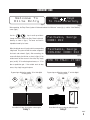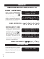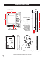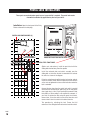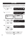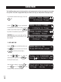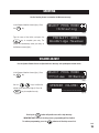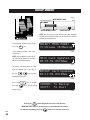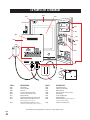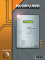
1
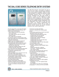
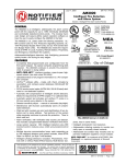
DIAL CODE LC SERIES
O
W
N
E
R
S
M
A
N
U
A
L
Telephone entry system with two line large liquid crystal display
VISIT US ON THE WEB
www.eliteentryphone.com
®
MADE IN USA
DECEMBER 1999
TABLE OF CONTENTS
Product Overview
2
3-4
Resident Use
4
Screen Saver Mode
Entry Phone Features
5-7
Mounting Installation
8
Wiring Diagram
9
Postal Lock Installation
10
Port Connectors
11 - 12
RF & RS485 Connections
13 - 14
Memory Card Installation
15
Viewing Software Version
15
Connecting Keypad Light Wires
16
Warnings and Precautions
16
Programming the Processor
17
Selecting Program Mode
18
Tenant Information
19
Transmitter/Card Programming
20
Area Codes
21
Utility Codes
22
Password
23
Clock Timer
24 - 26
Strike Time
27
Talk Time
27
Report Printing
28
Greeting
29
Volume Adjust
29
Backup Memory
30
Error Messages
31
Parts List & Diagram
32
Approvals
33
© 1997 BY ELITE ENTRY PHONE ALL RIGHTS RESERVED. NO PART
OF THIS MANUAL MAY BE REPRODUCED IN ANY MEANS GRAPHIC,
ELECTRONIC OR MECHANICAL,
INCLUDING PHOTOCOPYING WITHOUT THE EXPRESSED WRITTEN
PERMISSION OF THE PUBLISHER.
MATERIALS, COMPONENTS AND
SPECIFICATIONS ARE SUBJECT TO
CHANGE
WITHOUT
NOTICE.
RELEASE 1
LCD MANUAL
VERSION 1.31
Please do not attempt to
repair the Entry Phone
unless you are an authorized service technician!
PAGE
Thank you.
1
PRODUCT OVERVIEW
STANDARD FEATURES
• Two line Large LC Directory.
• Names listed in Directory in alphabetical order.
• Memory capacity: 25, 50, 150, 250, 500, 1000 names.
• User-friendly programmability via built-in alpha-numeric
keyboard eliminates the need for user's manual.
• Four character alpha-numeric password required to enter
programming mode.
• Programmable Utility keycodes for keyless entry.
• 60 Utility keycodes available per system.
• Time zones associated with Utility keycodes.
• Programmable real-time clock with leap year & daylight
savings compensation.
• 2 programmable 7-day timers for door and gate control.
• Programmable talk time.
• Touch-tones through microphone are ignored by system.
• System mutes tones in speaker during dialing.
• Postal lock capability.
• Surge protection;
• Power line: 5,000 volts surge protection.
• Tel line:800V (100A) surge protection.
• Immune to 25,000V electrostatic discharge.
• Two output relays with independent strike times.
• Relay output for VCR time lapse recorder to record 5
seconds per transaction.
• Power failure backups:
• Battery backup for complete function for 5 hrs.
• Battery enables dial out, program, & display.
• Non-Volatile removable SRAM memory has
unlimited write cycles (unlike EEPROM).
• Non-Volatile Real Time Clock/Calendar.
• High quality voice communication system with background noise filtering.
• Voice messages (digital) to help & guide user.
• Volume control via software.
• Non-Volatile PCMC 1A memory card
• Two (2) slots for PCMCIA memory cards. Second slot
used for file backup.
• Double box with built-in full keyboard for data processing.
• Parallel printer interface common to all computer printers.
• Print reports of programmable information.
• Printer error/Paper empty detection.
• By pressing '9' for gate or '5' for door, communication is
not lost. Talk time is extended to avoid unpleasant cutoff
between visitor and resident.
• Both DTMF tone and rotary dial detection.
• Programmable via modem-2400 bps (optional).
• FCC part 68 ,15 & Canadian DOC approval
SPECIFICATIONS
• Construction: Front Panel: 16 gauge stainless steel.
Processor Containment Box: Gold/zinc plated, powder
coated 16 gauge metal (weather resistant finish)
• Entire system is rain resistant.
• Power Input: 12 VAC, 40VA UL listed transformer(provided).
• Jack Type: USOC RJ11C or W
• Operating Environment:
• Temperature: -40 F to +185 F.
(Heater kit available at additional cost.)
• Relative Humidity: 5% - 95% non-condensing.
• Dimensions: 11 1/4" W X 16 7/16" H X 3 3/16" D
• Shipping Weight: Approximately 25 lbs.
3 YEAR WARRANTY
FACTORY TO DEALER
PAGE
2
RESIDENT USE
Welcome To
Elite Entry
Use
Keys
To View Directory
(fig a.)
(fig b.)
When operating, the Entry Phone System will alternate between the “Welcome” screen (fig a.) and the “View Directory”
screen (fig b.).
Use the
keys to scroll up and down
through the names listed in the Entry Phone’s electronic
directory as shown in (fig c.) The names are listed in
Fairbanks, George
CODE: 012
(fig c.)
alphabetical order by last name.
When the desired name is found, enter the corresponding
3-digit code. The system will dial the number assigned to
the tenant code entered. (fig d.) After connecting, the
Fairbanks, George
DIALING! CODE: 012
(fig d.)
screen will display the talk time as shown in (fig e.) If the
resident wants to allow access to the visitor, they simply
press (or dial) “9” for vehicular gate entrances, or “5” for
door or pedestrian gate . If the resident wants to deny
TIME TO TALK> 17 SEC
___
access, they simply hang up the phone.
By pressing or dialing the number “9” on their digital
or rotary phone,
WXY
9
(fig e.)
By pressing or dialing the number “5” on their digital
or rotary phone,
JKL
OR
5
OR
the resident will open the vehicular entrance gate.
the resident will open the door or pedestrian gate.
Entry 1
Entry 2
PAGE
3
RESIDENT USE
USING KEYCODES AND UTILITY CODES (ACTIVE ENTRY 1 ONLY)
RESIDENT 6-DIGIT KEYCODES
* ACCESS GRANTED *
Please Enter
Residents are assigned a 6-digit, personalized keycode for accessing the facility. To use the keycode
assigned, the resident must first push the
(fig a.)
key once and enter their keycode. The screen will
display “Access Granted” (fig a.) and access will be
allowed. If an incorrect keycode is entered, the system will inform the user of the invalid entry (fig b.)
* INVALID ENTRY *
Invalid 6-Digit Code
(fig b.)
The resident can then re-enter their keycode.
0
EXAMPLE - KEYCODE 002543 =
0
2
5
4
3
INDIVIDUAL UTILITY CODES
All systems, no matter what the memory capacity,
are equipped with 60 different Utility codes. To
access the facility within the time zone set, the
Utility Company must first press the
* ACCESS GRANTED *
Please Enter
key
(fig c.)
TWICE and then enter their 4-digit code. If it is
access will be allowed. If, however, it is not within
* ACCESS DENIED *
Not In Access Period
the time zone for entry, the display will inform the
(fig d.)
within the programmed time zone for entry, the
screen will display “Access Granted” (fig c.) and
user and access will not be allowed (fig d.)
8
EXAMPLE - UTILITY CODE 8716 =
7
1
6
SCREEN SAVER MODE
If the Dial Code System is inactive for 15 seconds it
will go into sleep mode. The screen will continue to
PRESS ANY KEY
display the scrolling message “Press Any Key”
until a key is pressed. The Screen saver mode is not
available while in program mode.
PAGE
4
(fig e.)
ENTRY PHONE FEATURES
Memory Card Slot
Memory Card Release Buttons
Backup Memory Card Slot
Processor Key Release / Lock
Memory Card
Mounting Hole
External Microphone
Power Switch
Mounting Hole
LC Display
Processor Unit
Processor
Containment Box
Display
Window
Dialing Keys
Programming Keys
Key Lock
External
Keypad
Printer Parallel Port
Stainless
Steel Door
Mounting Hole
Optional RF
Receiver Mount
External
Speaker
Conduit Knock-outs
Communication Port
Mounting Hole
Input/Output Connector
Phone Jack (RJ11)
Postal Lock Setup
All components and specifications are subject to change without notice.
PAGE
5
ENTRY PHONE FEATURES
1
5
1
EXTERNAL MICROPHONE
2
KEY LOCK - Opens the Processor
Containment Box to access the
Processor.
3
HELP KEY - With digital voice messages to help guide the user.
4
EXTERNAL SPEAKER
5
DISPLAY WINDOW - Heavy-duty, 3/8”
thick protective lens.
6
DIALING KEYS LIGHT - Lights up
dialing keys for easy visibility.
7
PHONE DIALING KEYS - Used to dial
residents / keycodes
8
SCROLL KEYS - Scrolls through
names in alphabetical order on
screen.
9
UNLOCK KEY - Residents and utility
personnel use this key with their key
code to open gate.
10
HANG-UP KEY - Pressed when user
wants to hang up.
11
ACCESS FOR POSTAL LOCK
12
16 GAUGE STAINLESS STEEL DOOR Heavy-duty and weather resistant.
6
1
4
7
2
3
HELP
2
5
8
0
3
6
9
7
A
Z
8
9
10
4
11
12
All components and specifications are subject to change without notice.
PAGE
6
ENTRY PHONE FEATURES
16
15
14
17
13
13
POWER ON/OFF SWITCH
14
MEMORY CARD RELEASE BUTTONS - Eject
Memory Cards when pressed.
15
CARD SLOTS - Front slot holds Backup Memory
Card or RF Card, back slot holds Main Memory
Card.
16
MEMORY CARD - Stores all programmed
information.
17
TWO LINE, LARGE LIQUID CRYSTAL DISPLAY Displays
information
and
instructions,
two lines at a time.
18
DIRECTION KEYS - Move cursor to desired
position within screens.
19
HELP KEY - Helps user while in programming
or user modes.
20 ERASE KEY - Erases information screens
no longer needed.
18
19
21
EXIT KEY - Press this key to go back to previous
screen / menu.
22
PROGRAM KEY - Sets Processor to program
mode.
23
ENTER KEY - Registers information into memory
after it is typed.
24
PRINTER PARALLEL PORT - Enables printing of
programmed information.
25
COMMUNICATION PORT - RF Interface for future
remote control and card access use.
29
20
28
21
22
23
24
25
26
27
26 INPUT/OUTPUT CONNECTOR - Main power,
input/output connection.
27
PHONE JACK (RJ11) - Connects to main
phone line.
28
KEYBOARD - Works like standard keyboard to
type in information and names.
29
SCROLL KEYS - Scrolls through screens /
menus.
All components and specifications are subject to change without notice.
PAGE
7
MOUNTING INSTALLATION
WALL
MOUNTING HOLES 1/4” dia.
1”
1.5”
2 1/2”
8 3/4”
FOR INSTALLATION
ON WALL
14 1/2”
14 9/16”
Remove the Processor
Unit from the Processor
Containment Box and
bolt the Processor
Containment Box to
recess in wall using the
four mounting holes.
Feed the power and
phone lines through the
appropriate holes for
connecting to the
Processor Unit.
4 1/2”
6 3/4”
CONDUIT KNOCK-OUTS 7/8” dia.
1 7/8”
2 1/8”
1 1/16”
16 7/16”
11 1/4
3 3/16
NOTE: Be sure to install the Entry Phone at normal eye level
All components and specifications are subject to change without notice.
PAGE
8
WIRING DIAGRAM
AWG
ELITE ENTRY PHONE
MAX.
DISTANCE
24
170’
22
280’
20
450’
18
700’
16
1100’
“DEDICATED”
TELEPHONE LINE
12VAC 40VA
see chart above
for distance
US
OC
RJ
11
C
BLACK/WHITE
2 BLUE WIRES
ENTRY 2
2 YELLOW WIRES
ENTRY 1
LOCK
PEDESTRIAN GATE
CONDUIT
VEHICULAR GATE
ENTRY DOOR
OR
MASTER GATE OPERATOR
(STRIKE OPEN INPUT)
ACCESS DOOR
WXY
9
OR
Connect the two yellow wires to the main
vehicular gate operator or door. The gate/door
will be activated by either pressing 9 from the
residents side, or by using a utility keycode,
individual keycode or optional RF transmitter
from Entry Phone side. (Refer to page 12 &
13)
WXY
5
Connect the two blue wires to the secondary
gate or door. The gate/door will only be
activated from the residents side by pressing 5.
(Refer to page 27 to adjust the strike times).
PAGE
9
POSTAL LOCK INSTALLATION
These parts are used only when postal access to your facility is required. The postal lock mechanism must be obtained by application to your local post office.
Installation: Open the front panel of the Entry
Phone and remove the hole plug.
POSTAL LOCK SWITCH WIRES (2)
POSTAL LOCK
SWITCH ASSEMBLY
SWITCH ASSEMBLY
MOUNTING HOLES
(MOUNT WITH POSTAL LOCK ON
ENTRY PHONE FRONT PANEL)
KNOCK OUT HOLE FOR POSTAL LOCK
STAINLESS STEEL FRONT PANEL
(Retain nuts and washers) Install the postal lock with the
sliding bolt oriented away from the speaker.
Install the enclosed plate end switch assembly over the
sliding bolt so that when the bolt is extended it will activate
the switch as shown in the diagram.
POSTAL LOCK
Fasten by using the enclosed flat washer, lock washer, and nut
on each of the four studs. Adjust the plate and switch location
as the nuts are tightened to ensure switch activation when the
bolt is extended.
Connect the two wires from the postal lock switch in parallel
with either the two blue wires (door relay) or the two yellow
wires (gate relay) at the 15 pin input/output connector. Note
that polarity or color coding is not required. As example: If
you wish to activate the door using the postal lock switch,
connect wire 1 from the switch to one of the blue wires and
connect wire 2 from the switch to the other blue wire.
Test operation by activating the lock. Ensure that full
extension of the sliding bolt will not bend or break the switch.
PAGE
10
INPUT/OUTPUT PORT CONNECTOR
Entry Phone Processor
8
USOC RJ11C
Telephone Line
(included)
OPTIONAL
Parallel Printer Port
connection see page 28
3
HEATER: For use with the white wire to allow
optional heater kit to be connected. Relay goes on at
0°f and off at 20°f.
Microphone (-)
VCR RELAY: For use with Time Lapse VCR. Each time
access is granted, the VCR Relay is activated for 5
seconds, allowing recording of all access to facility.
12VAC Transformer (black)
2
Microphone (+)
SPEAKER TERMINAL: Pre-installed speaker output.
5
12VAC Transformer / Heater (white)
1
4
Door Relay N O (blue)
3
Door Relay COM (blue)
Gate Relay COM (yellow)
Gate Relay N O (yellow)
2
Heater (red)
VCR Relay COM (green)
1
VCR Relay N O (green)
Speaker Terminal 1
Speaker Terminal 1
OPTIONAL
9-Pin Communication port
connection - for optional
RF and RS-485 products
15 Pin
Input / Output
Connector
7
6
5 DOOR RELAY: For allowing access through pedestrian gate or door.
6 12 VAC: Power supply to the Entry Phone.
7 MICROPHONE: Pre-installed microphone input.
4
GATE RELAY: for use with gate operator to
control access through main vehicular gate.
8 TELEPHONE LINE: Standard USOC RJ11C phone line
(included) to be connected to standard phone jack.
NOTE: Telephone line used for phone entry system must
be a dedicated line.
PAGE
11
COMMUNICATION PORT CONNECTORS
Entry Phone Processor
3
USOC RJ11C
Telephone Line
(included)
OPTIONAL
Parallel Printer
Port connection
see page 28
RS485 (-) (blue)
12
RS485 (+) (brown)
PAGE
RS485 (Ground) (Yellow)
1
RF Receiver (Ground) (white)
RF Receiver (Data) (green)
RF Receiver (Power) (black)
OPTIONAL
9-Pin Communication
port connection - for
optional RF and RS-485
products
15 Pin
Input / Output Connector
2
1
RF RECEIVER: For use with local RF receiver. (See Receiver Connection Manual.)
2
RS485: Connect to corresponding RS485 terminals (-, +, GND) of remote security devices.
3
TELEPHONE LINE: Standard USOC RJ11C phone line (included) to be connected to standard phone jack.
RS-485 CONNECTION EXAMPLE
RF Receiver wires
BLACK
GREEN
WHITE
LOCAL
RF RECEIVER
RS485
wires
RS485 (-) (blue)
RS485 (+) (brown)
1
2
3
4
5
6
7
8
9
*
0
#
RS485 GND (yellow)
KEYPAD
RS 485 REMOTE DEVICE 1
STAND-ALONE RECEIVER
RS 485 REMOTE DEVICE 2
CARD READER
RS 485 REMOTE DEVICE 3
UNIVERSAL INTERFACE BOARD
RS 485 REMOTE DEVICE 4
NOTE: To support RS485 devices you must install the Communicator Card.
PAGE
13
RS-485 CONNECTION CONFIGURATIONS
“Daisy Chain” wiring configuration
Configuration #1
(Recommended method for superior data transmission)
• Up to 31 RS-485 devices supported
• Maximum distance from the last RS-485 device to the Entry Phone is 4000 Ft.
• Turn “ON” the terminator switch ONLY for the last device installed in the RS-485 line.
• Use 22 AWG twisted pair shielded wire
Turn Terminator Switch “ON”
for Last Device on Wire Run
Gnd
+
–
4000 Ft Max.
Each RS-485 device must have a unique “Device ID Number” set by using the rotary switches on the device. (Refer to specific RS-485 Instruction sheets).
Configuration #2
“Star” wiring configuration
• Maximum number of wire runs allowed is 7
Turn Terminator Switch “ON”
for Last Device on Wire Run
Turn Terminator Switch “ON”
for Last Device on Wire Run
• Maximum number of RS-485
devices present on ALL wire runs
is 31.
4000 Ft Max.
• Maximum distance from the last RS-485 device
(per wire run) to the Entry Phone is 4000 Ft.
– + Gnd
Wire Run
Turn Terminator Switch “ON”
for Last Device on Wire Run
• Use 22 AWG twisted pair shielded wire
Turn Terminator Switch “ON”
for Last Device on Wire Run
Turn Terminator Switch “ON”
for Last Device on Wire Run
Turn Terminator Switch “ON”
for Last Device on Wire Run
Turn Terminator Switch “ON”
for Last Device on Wire Run
Each RS-485 device must have a unique “Device ID Number” set by using the rotary switches on the device. (Refer to specific RS-485 Instruction sheets).
PAGE
14
MEMORY CARD INSTALLATION
(fig a.)
A. Turn power on and insert Memory
Card into Main Memory Card Slot
(Main Memory Card in back slot,
Backup Memory Card in front slot.)
(fig a.) Push it all the way in until card
“snaps” into place and the release
button pops up. The screen should
display the “Welcome Screen” (fig b.)
B. If the screen continues to display
the “Insert Memory Card” screen
(fig c.) then Eject memory card by
pressing the corresponding release
button down and reinsert Memory
Card into main slot (fig d.). Otherwise
continue with programming.
TOP VIEW OF PROCESSOR
MAIN MEMORY CARD
BACKUP MEMORY CARD OR
COMMUNICATOR CARD FOR
RF DEVICES/RS485
BACK
FRONT
POWER SWITCH
Welcome To
Elite Entry Phone
(fig b.)
Insert Memory Card
IN MAIN SLOT
(fig c.)
VIEWING THE SOFTWARE VERSION
(fig d.)
A. To view the memory capacity of the system or to view
the software version currently running on the system in
operation an information screen is accessible on all Dial
Code systems for easy reference. Turn power off and insert
Memory Card in Main Memory Slot. Turn power on and the
information screen should display as seen in (fig e.)
MEMORY CAPACITY
DIAL CODE VF-250
REV. 1.00_
(fig e.)
SOFTWARE VERSION NUMBER
PAGE
15
CONNECTING KEYPAD LIGHT WIRES
IF YOU ARE USING THE PHONE’S OWN TRANSFORMER FOR POWER:
STEP 1 Unplug the transformer.
STEP 2 Connect the black and white wire on the light in parallel
with the black and white wires on the phone.
STEP 3 Stow the wires in the bottom of the box neatly.
STEP 4 Plug in the transformer. Test the phone for normal function.
All five lights in the hood should be lit.
IF YOU ARE USING A SECOND TRANSFORMER TO POWER THE LIGHT:
(Time clock or existing security lights)
STEP 1 Run your wires to a place to plug in the 12V transformer.
STEP 2 Wire the black & white wires to the 12V (AC or DC)
transformer per all local codes & standards.
STEP 3 Plug in the transformer. Test the phone for normal function.
All five lights in the hood should light with the power on.
WARNINGS AND PRECAUTIONS
A
25
0
B
A. The Entry Phone is only water resistant when the Stainless Steel
Door is closed and locked. Do not expose the Processor Unit or the
open Processor Containment Box to rain, snow, or harsh weather
conditions. Do not drop the Processor or expose it to impact.
B. Do not touch the terminals. Do not bend, drop or expose to impact.
PAGE
16
PROGRAMMING THE PROCESSOR
ENTERING THE PROGRAM MODE
When the Processor unit is turned on and the
button is pressed, the screen will display:
TO ENTER PROG MODE,
Type Password >____
Type in the factory present password (7777). Press
will display:
. The Program Selection Screen
SELECT PROG MODE:
(N)Names (U)Utility
If you enter the wrong password, the screen will prompt you to try again:
INVALID PASSWORD
(R)Retry (EXIT)Quit
Press
R
to retry entering your password. Press
Pressing the
to quit the programming menu.
button will provide users with a help message.
IMPORTANT NOTE: While in the help screens, programming will be disabled.
To continue programming, press the
button to exit the help screens first.
PAGE
17
SELECTING PROGRAM MODE
LIST OF PROGRAM MODES:
page 19-21
1
Names
N
Program or edit Tenant Names
2
Utility
U
Program or edit Utility Codes
page 22
3
Password*
P
Program New Password ( recommended )
page 23
4
Clock/Timer
C
Program System Clock and Seven Day Timers
5
Strike Time
S
Program relay output time ( for 2 relays )
page 27
6
Talk TIme
T
Program length of Talk Time
page 27
7
Report Printing
R
Program setup of different report printing
page 28
8
Greeting
G
Program custom Welcome Screen Message
page 29
9
Volume
V
Program Volume level
page 29
10
Backup
B
Backup of memory card
page 30
pages 24-26
*We recommend you customize your password to avoid unauthorized programming (see pg 23)
To select a Program Mode, press the corresponding letter from one of the ten options.
Use the
keys to scroll through the ten different Program Modes.
SELECT PROG MODE:
(N)Names (U)Utility
SELECT PROG MODE:
(T)Talk Time
SELECT PROG MODE:
(P)Password
SELECT PROG MODE:
(R)Report Printing
SELECT PROG MODE:
(C)Clock/Timer
SELECT PROG MODE:
(G)Greeting
SELECT PROG MODE:
(S)Strike Time
SELECT PROG MODE:
(V)Volume (B)Backup
Pressing the
button will provide users with a help message.
IMPORTANT NOTE: While in the help screens, programming will be disabled.
To continue programming, press the
PAGE
18
button to exit the help screens first.
TENANT INFORMATION
STEP
1 In the Program Selection Screen (fig a.), Press the
SELECT PROG MODE:
(N)Names (U)Utility
N
key. The screen will display (fig b.):
PROG A NEW NAME
PROG BY CODE:___
(fig a.)
STEP
2
(fig b.)
You now have three options:
To program by code, enter
To program by name, press
N
the
N
key and the first
OR
a three digit code* and press
the
empty code will display.
To view or edit an existing name
OR
key.
or code, use the
keys to scroll through Directory.
* The unit will only accept codes within it’s
range - depending on memory capacity.
STEP
3
Type in the desired Tenant name, LAST name first, followed by the first name (fig c.). If the code you have
selected is already used, there will be a name already. You can edit the name by simply typing over it.
Press the
key to complete the entry. You may also use the
keys to move the cursor
within a code.
Tenant code
005 LastNAME,First
Jones, Robert_
Tenant name
STEP
4
005 PHONE NUMBER:
_-___-496-2634
(example - fig c.)
(example - fig d.)
Type in the desired Tenant phone number (fig d.). If you need to enter an area code refer to the next page.
Press the
key to complete the entry. The KEY CODE screen will be displayed.
(example - fig e.)
STEP
5
An individual six digit Tenant Key code may be
assigned to each tenant . Tenants can use their
Key Code to access the premises.
005 KEY CODE:
005123
Assignment of Tenant Key Codes is optional. The first three digits of the Key Code is the assigned Directory
Code. Assign the last three digits (numeric characters only) to create an individual Key Code. If using the RF
Card, proceed to Step 6 (fig e). Press the
key.
PAGE
19
TRANSMITTER/CARD PROGRAMMING
STEP
6
To complete entry, press the
key to return to the program selection screen.
To program RF devices ( i.e. transmitters/cards etc.) continue on to Step 7.
NOTE: To enable the transmitter/card programming feature, you must insert the communicator card
in the “backup” slot before you turn on unit. (refer to memory card installation section of manual)
STEP
7
Use
keys to view
and program up to 10 transmitter or
card codes associated to the directory
code.
To program a transmitter or card code,
005 TRANSM/CARD#1:
___-_____ (S) SCAN
005 TRANSM/CARD#2:
___-_____ (S) SCAN
••
••
you may enter the code manually using
005 TRANSM/CARD#10:
___-_____ (S) SCAN
the keypad or you may scan the
transmitter/card code.
STEP
8
ECR-485W
To scan a card code, press the “S” key and
(fig a.)
activate the card as shown in fig a.
To scan a transmitter code, press the “S” key
and activate the transmitter as shown in fig b.
Touch the card to the card reader
to activate remote device
(fig b.)
Processor
Stand Alone Reciever
Model ERRB 485
Press button on transmitter
to activate remote device.
STEP
9
Repeat steps 7 and 8 for up to ten devices per directory code. After the last device has been programmed,
press
or
key to return to the program selection screen.
NOTE: The time zones and restrictions associated with transmitter/card codes can only be programmed
remotely using the EMS modem software.
PAGE
20
AREA CODES
005 PHONE NUMBER:
_-___-___-____
PREFIX FIELD
AREA CODE FIELD
(fig a.)
In special applications, it is necessary to enter area codes for Tenant Phone Numbers. Area codes are
entered from the Phone Number screen (fig a.).
005 PHONE NUMBER:
1-___-___-____
(fig b.)
Use the
key to enter the area code and prefix field (fig b.). The Prefix defaults to “1” for normal
11-digit dialing. Where necessary, you can change the prefix to any number. To choose 8, 9, or 10-digit
dialing, when no prefix is needed, press
while in the prefix field. Then type the required
number of digits in the area code field followed by the phone number. Press the
key to
continue with the entry as described on the Page 19.
To erase “Tenant” information, press the
key. Press the
key for assistance.
IMPORTANT NOTE: While in the help screens, programming will be disabled.
To continue programming, press the
button to exit the help screens first.
PAGE
21
UTILITY CODES
A 4-digit Utility Code (numeric characters only) may be assigned to “Utility Companies” such as delivery, telephone,
construction companies, water, power, etc. These utilities can use their individual code to access the premises
within the time zone that you program. Each system, no matter what the memory capacity, is equipped with 60
available Utility Codes and time zones.
STEP
Screen (fig a.),
1 InPressthe theProgramU Selection
key. The screen will
display (fig b.):
SELECT PROG MODE:
(N)Names (U)Utility
(fig a.)
STEP
2
You now have two options:
PROG UTILITY CODE> N
View/Edit Codes >
(fig b.)
To program a new Utility Code, press
N
the
STEP
3
key and type in a 4 digit
Use the
OR
keys to view
or edit existing Codes. The last screen
code. If the code entered is used, type
will display memory spaces available.
in another.
Select a code that you wish to edit.
Press the
key or the
key to enter code. Type the name of the
utility in the screen that follows and
press the
UTILITY CODE:4762
NAME:FedEx
(example - fig c.)
key or
(fig c.).
STEP
4
Enter the desired time zone in the
screen that follows (fig d.)
Use the
keys to move the
4762 TimeZone
09:00AM To 05:00PM
(example - fig d.)
cursor. To view the previous screen, use
the
key. Press the
key to complete your transaction.
To erase “Utility” information, press the
key. Press the
key for assistance.
IMPORTANT NOTE: While in the help screens, programming will be disabled.
To continue programming, press the
PAGE
22
button to exit the help screens first.
PASSWORD
The factory present password is 7777. We suggest that you customize it.
In the Program Selection Screen (fig a.), Press the
P
key.
SELECT PROG MODE:
(P)Password
(fig a.)
To customize a password, type in a four character
password (it may be alphanumeric characters).
Press the
key to enter the new
password. It will be displayed by asterisk (*) for
NEW PASSWORD:
****
security (fig b.) (To leave the password unchanged,
press the
(fig b.)
key.)
A confirmation screen will appear (fig c.). Type in
the same password and press the
key.
If you enter a different password, the password will
RE-ENTER PASSWORD:
****
not be confirmed and you will have to repeat the
(fig c.)
transaction.
Always remember your password! This password is required to enter the Program Mode. If you lose your password,
you will need to contact the manufacturer to reissue a new password.
Pressing the
button will provide users with a help message.
IMPORTANT NOTE: While in the help screens, programming will be disabled.
To continue programming, press the
button to exit the help screens first.
PAGE
23
CLOCK/TIMER
The Clock/Timer allows you to set the date and time, and to program gates and doors to be opened or closed whenever specified. This clock is equipped with 100 year calender, auto leap year compensation and daylight savings.
In the Program Selection Screen (fig a.), Press the
C
key.
SELECT PROG MODE:
(C)Clock/Timer
(fig a.)
Use the
keys to scroll between
the three different menu choices (fig b.). Select the
number of your choice or press the
key while on the selection of your choice.
CAUTION: Make sure to set the Date and Time
before programming the clock timers for the
door and gate.
PROG CLOCK/TIMER
(1)Date & Time
PROG CLOCK/TIMER
(2)Gate Timer
PROG CLOCK/TIMER
(3)Door Timer
(fig b.)
1. DATE AND TIME
Use the
1
the
key to set the Date and time, use
keys to move the cursor. Press the
key to enter your input.(fig c.)
Use the
(fig c.)
keys to select the
current day of the week. Press the
key
to enter your input. (fig d.)
Select daylight savings by pressing
yes or
N
for no. The
complete the date and time entry. (fig e.)
DATE>02-11-96
Time>07:31am p=pm
Today Is THURSDAY
Use
To Select Day
(fig d.)
Y
for
key will
Daylight Savings>y
(Y)Yes (N)No
(fig e.)
PAGE
24
CLOCK/TIMER CONTINUED
2./ 3. DOOR AND GATE TIMERS
Press
2
to program Gate Timers Menu.
Press
3
to program the Door Timers Menu.
Setup New Timers> N
View/Edit Timers>
Use
to view and program timer(s) for
Sunday through Saturday. Move the cursor
to time and type in the setting. Two timers can be set
for each day of the week following the procedure below.
(fig a.)
See next page for instructions
USE ARROWS TO VIEW / PROGRAM
INDIVIDUAL TIME ZONES
SUN G-Tmr1: ON F=off
07:00am -> 05:00pm
MON G-Tmr1: ON F=off
08:00am -> 04:30pm
••
••
SAT G-Tmr1: ON F=off
07:00am -> 05:00pm
(fig a.)
Program timers 1 & 2 for any day of the week (fig b. & c.)
Press
N
to turn timer 1 ON or press
F
to
turn timer 1 OFF. Press the
key. Type the
desired timer 1 setting. For am type
A
type
P
Press
For pm
to program the timer 2.
SUN G-Tmr1: ON F=off
07:00am -> 05:00pm
(fig b.)
SUN G-Tmr2: ON F=off
07:00am -> 05:00pm
(fig c.)
To program the second timer, repeat the above procedure. Press the
To exit “Timers” screen, press the
key. Press the
key when complete.
key for assistance.
IMPORTANT NOTE: While in the help screens, programming will be disabled.
To continue programming, press the
button to exit the help screens first.
PAGE
25
CLOCK/TIMER CONTINUED
2./ 3. DOOR AND GATE TIMERS, cont’
Press
2
to program Gate Timer Menu
Press
3
Setup New Timers> N
View/Edit Timers>
Program timers 1 & 2 for any day of the week (fig d.)
Press
N
to turn timer 1 ON or press
F
to
to program the Door Timers Menu
PRESS (N) TO PROGRAM
SETS OF TIME ZONES
See previous page for instructions
GATE Tmr1: ON F=off
__:__am -> __:__pm
(fig d.)
turn timer 1 OFF. Press the
key. Type the
desired timer 1 setting. For am type
A
type
P
Press
For pm
to program the timer 2.
To program the second timer, repeat the above
procedure. Press the
key when complete.
Timer 1 & 2 settings can be copied to any day(s) of the
week. Select the day(s) of the week to be copied.
Press
Y
to select day or press
select day of week. Press
N
to not
when complete.
(fig e.)
GATE Tmr2: ON F=off
__:__am -> __:__pm
COPY Timers1,2 To
Workdays(y) Sun(n)
COPY Timers1,2 To
Mon(n) Tue(n) Wed(n)
COPY Timers1,2 To
Thr(n) Fri(n) Sat(n)
(fig e.)
To exit “Timers” screen, press the
key. Press the
key for assistance.
IMPORTANT NOTE: While in the help screens, programming will be disabled.
To continue programming, press the
PAGE
26
button to exit the help screens first.
STRIKE TIME
Strike Time sets the amount of time your gate or door relay will be held open.
In the Program Selection Screen (fig a.), Press the
S
SELECT PROG MODE:
(S)Strike Time
key.
(fig a.)
The strike time can be set for both gates and doors
Door Strike Time > D
Gate Strike Time > G
(fig b.)
(fig b.)
Press the
D
key to set the Door Strike Time. Type in
Press the
G
key to set the Gate Strike Time. Type in
a time from 1 to 99 seconds (fig c.). Press the
a time from 1 to 12 seconds (fig d.). Press the
key to enter your selection.
key to enter your selection.
DOOR STRIKE TIME:
[01-99] 10 Seconds
GATE STRIKE TIME:
[01-12] 05 Seconds
(fig d.)
(fig c.)
GATE NAME/LOCATION
North Side Gate
DOOR NAME/LOCATION
South Entry Door
(fig f.)
(fig e.)
For either the Gate or Door Strike TIme, you may now type in a name and location (up to 13 characters) to which you want
the programmed strike time applied. (fig e.) and (fig f.) Press the
key to complete the transaction.
TALK TIME
You can set the amount of time to talk on the Entry Phone at 20, 40, or 80 seconds.
SELECT PROG MODE:
(T)Talk Time
TALKTIME IS 20 SEC
(B)40 Sec (C)80 Sec
(fig h.)
(fig g.)
In the Program Selection Screen (fig g.), Press the
seconds,
B
for 40 seconds, or
C
T
key. Choose the desired Talk Time, press
for 80 seconds (fig h.). Press the
A
for 20
key to confirm your entry.
PAGE
27
REPORT PRINTING
If your Processor is connected
to a printer using the Parallel
Printer Port, you will be able to
print selected tables.
In the Program Selection Screen (fig a.),
Press the
R
key.
SELECT PROG MODE:
(R)Report Printing
(fig a.)
PRINT REPORT:
Names In Order
FOUR DIFFERENT PRINTING OPTIONS
>N
Scroll through the printing options using the
keys. Press the corresponding
(fig b.)
PRINT REPORT:
Codes In Order
letter or the
>C
(fig c.)
PRINT REPORT:
Utility Keycodes >U
key to print. There are
four options to print; all tenants names in order
(fig b.), All tenants codes in order (fig c.),
Utility Keycodes (fig d.), or 7-Day Timer
settings (fig e.).
(fig d.)
PRINT REPORT:
7-Day Timers
>T
(fig e.)
PAGE
28
NOTE: Printer must be setup to accept standard
ASCII format input. May not work on all printers,
to find out if your printer will accept ASCII format,
check the owners manual that came with your
printer or call your printer’s manufacturer.
GREETING
Use the Greeting Screen to customize the Welcome message.
In the Program Selection Screen (fig a.), Press
the
G
key.
SELECT PROG MODE:
(G)Greeting
(fig a.)
Type the name of the facility and press the
key to complete your entry. The
system will automatically center your entry on
FACILITY NAME:
Woodbridge Meadows
(fig b.)
the Welcome screen.(fig b.)
VOLUME ADJUST
Use the Speaker Volume Screen to adjust both voice message and speakerphone volume levels.
In the Program Selection Screen (fig c.), Press
the
V
key.
SELECT PROG MODE:
(V)Volume (B)Backup
(fig c.)
Use the
keys to adjust the
volume to the desired level (fig d.). Press the
key to complete the entry.
Pressing the
SPEAKER VOLUME>
___________ +
(fig d.)
button will provide users with a help message.
IMPORTANT NOTE: While in the help screens, programming will be disabled.
To continue programming, press the
button to exit the help screens first.
PAGE
29
BACKUP MEMORY
(fig a.)
TOP VIEW OF PROCESSOR
MAIN MEMORY CARD
BACKUP MEMORY CARD
POWER SWITCH
BACK
FRONT
NOTE: You must have an extra memory card (sold separately)
installed in the Backup Slot (fig a.) of the Processor in order to
perform the backup process.
In the Program Selection Screen (fig b.),
Press the
B
key.
SELECT PROG MODE:
(V)Volume (B)Backup
Insert additional memory card in the
Backup Slot.
(fig b.)
NOTE: Back-up Memory card must be
the same size or greater than the Main
Memory card being backed up.
MAIN Card Updated On
05-15-96 03:50am
(fig c.)
The screens will display when the cards
were last updated. (fig c.) and (fig d.)
Use the
keys to scroll
through the information.
BACKUP Card Updated
02-11-96 04:20am
(fig d.)
Press the
key to Backup.
Press the
key to exit the backup
process (fig e.).
(ENTER) To Backup
(EXIT) To Quit
(fig e.)
Pressing the
button will provide users with a help message.
IMPORTANT NOTE: While in the help screens, programming will be disabled.
To continue programming, press the
PAGE
30
button to exit the help screens first.
ERROR MESSAGES
OUT OF RANGE CODES: If the processor detects
one or more 3-digit codes present on the memory
card inserted that cannot be accessed, an error
message is displayed. (fig a.) Codes that cannot be
accessed by the limitation of the system being used
cannot be edited.
LOW BATTERY If the battery backup is reaching it’s
minimal charge level, a battery icon with a “B” next
to it will display in the top right corner of the
display. (fig b.) An alert beep will accompany this
icon. The batteries must be charged to continue.*
If the battery backup level reaches it’s minimal
charge, an error message will display (fig c.) and
the system will become non-functional until the
battery backup is charged by using the plug in
transformer.*
LOW BATTERY ICONS: If a battery icon appears in
the top right corner of the display and the letter next
to it is an “M” or a “C”, as shown in figures d. and
e., contact Manufacturer for instructions.
949-580-1700
*IMPORTANT NOTE: In order to charge the battery in
the Dial Code System, the processor must be plugged
in to the transformer and the processor MUST BE ON.
If the power is off on the processor, the battery will
not be charging.
Codes Detected out
of Range, See Manual
(fig a.)
Welcome To
B
Elite Entry Phone
(fig b.)
Battery Is Low
It Must Be Recharged
(fig c.)
Welcome To
C
Elite Entry Phone
(fig d.)
Welcome To
M
Elite Entry Phone
(fig e.)
PAGE
31
LC PARTS LIST & DIAGRAM
T009
T010
T035
Memory Card
T038
T033
T030
T031
T027
T029
T003
T025
T002
T001
T014
T012
T026
T013
T011
PART #
DESCRIPTION
PART #
DESCRIPTION
T001
T002
T003
T009
T010
T011
T012
T013
Transformer
External Keypad
Key Lock
Processor Containment Box
Processor Key Release / Lock
Battery Backup
9 Pin Communication port Connector
Mobile Power Connection Kit (Includes:
T025
T026
T027
T029
T030
T031
T033
T035
Programming Keys
Postal Lock Assembly
LCD Processor
Key For Internal / External Lock
LCD Display
Kit For Keypad Light
Window Display
External Box Assy. (LC), (No Processor,
T014
External Box Connection Kit (Includes:
T038
Stainless Steel Door (LC)
transformer and 15 pin connector)
Postal Lock or Memory Card)
external mic, external speaker, & 15 pin connector)
All components and specifications are subject to change without notice.
PAGE
32
APPROVALS
FCC part 68, 15 & Canadian DOC approval.
Industry Canada (IC) Notice
Instruction to the User:
This equipment has been tested and found to comply with the limits for a class 13 digital device, pursuant to
part 15 of the FCC Rules. These limits are designed to provide reasonable protection against harmful
interference in a residential installation. This equipment generates, uses and can radiate radio frequency energy
and if not installed and used in accordance with the instructions, may cause harmful interference to radio
communications. However, there is no guarantee that interference will not occur in a particular installation. If
this equipment does cause harmful interference to radio or television reception, which can be determined by
turning the equipment off and on, the user is encouraged to try to correct the interference by one or more of the
following measures:
* Reorient or relocate the receiving antenna.
* Increase the separation between the equipment and receiver.
* Connect the equipment into an outlet on a circuit different from that to which the receiver is connected.
* Consult the dealer or an experienced radio/TV technician for help.
In order to maintain compliance with FCC regulations, shielded cables must be used with this equipment.
Operation with non-approved equipment or unshielded cables is likely to result in interference to radio and TV
reception. The user is cautioned that changes and modifications made to the equipment without the approval of
manufacturer could void the users authority to operate this equipment.
"Notice: The Industry Canada (IC) label identifies certified equipment. This certification means that the
equipment meets telecommunications network protective, operational and safety requirements as prescribed in
the appropriate Terminal Equipment Technical Requirements document(s). The department does not guarantee
the equipment will operate to the users satisfaction.
Before installing this equipment, users should ensure that it is permissible to be connected to the facilities of the
local telecommunications company. The equipment must also be installed using a acceptable method of
connection. The customer should be aware that compliance with the above conditions may not prevent
degradation of service in some situations.
Repairs to certified equipment should be coordinated by a representative designated by the supplier. Any repairs
or alterations made by a user to this equipment, or equipment malfunctions, may give the telephone
communications company cause to request the user to disconnect the equipment.
User should ensure for their own protection, that the electrical ground connections of the power utility, telephone
lines and internal metallic water pipe system, if present, are connected together. This precaution may be
particularly important in rural areas."
Caution: Users should not attempt to make such connection themselves, but should contact the appropriate
electric inspection authority, or an electrician, as appropriate.”
"Notice: The Ringer Equivalent Number (REN) assigned to each terminal device provides an indication of the
maximum number of terminals allowed to be connected to the telephone interface. The termination on a
interface may consist of any combination of devices subject only to the requirement that the sum of the Ringer
Equivalent Numbers of all the devices does not exceed 5."
PAGE
33