1
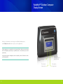
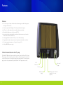
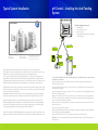
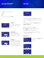
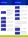
Model # RNOC2012 Ecosystem enabled OWNER’S MANUAL Leonardo™ Cell Easy to use with advanced features contents RadioNet™ RadioNet™ Outdoor Computer Display Screen 5 Features6 Typical System Installation 8 Installing the Acid Feeding System 9 Operating the RadioNet™ 10 Main menu 11 Changing pH Control12 Mineral Test13 Congratulations on your decision to purchase a RadioNet™ Outdoor Computer/Leonardo™ Cell. The Poolrite RadioNet™ Outdoor Computer contains many advanced features that are easy to set-up and control. Factory pre-set modes enable first time users to have an effective sanitation system and pH control from the outset. As competence in operating the system is acquired the numerous outstanding features of the RadioNet Outdoor Computer can be utilised. The Leonardo™ Cell has an innovative roller coaster design for high water velocity and far less resistance enabling efficient sanitation, reduced pump operating time and less energy consumption. This cell is optimised for low- flow energy saving pumps. 2 Super Sanitise Feature 13 Backwash Mode Feature 14 Settings screen 16 Changing Program Times 17 System Setup Feature 18 Winter Mode Feature 21 Input Port Feature 22 On screen Messages 25 Restore Defaults 26 System History Feature 26 Changing from Salt to MagnaPool 26 Leonardo™ Cell 27 Managing water quality 31 Customer Care & Checklist 37 Trouble-Shooting Guide 41 Warranty 45 3 RadioNet™ Outdoor Computer Display Screen Should you not find what you are looking for in this Owner Handbook please email [email protected] and we can point you in the right direction. Poolrite equipment is not intended for use by young children or infirm persons unless they have been adequately supervised by a responsible person to ensure that they can use the system safely. If any power supply cord is damaged, it must be replaced by a Service Technician in order to avoid a safety hazard. Press to select menu options Press arrow to change values 4 Press to select manual, automatic or system off mode Press arrow to change values 5 Features Features • For use on any pool system and the intuitive software design is suitable for beginners through to advanced users. • • • • Software is optimised for MagnaPool™ and compatible with salt systems. • • • • Six (6) programmable run times for full pool control. Control by days. pH Control - reliable and probeless via predictive dosing as standard. Mated with the high water velocity Leonardo™ Cell. Improved pool water chemistry balance and control helps save money on chemicals and increases sanitation effectiveness. Programmable sanitation output to suit pool requirements and weather conditions. Soft start programming ramps up cell output for longer cell life. Auxiliary 240V/50Hz power supply. *When Paired with Gemini Twin™ pump The RadioNet™ Outdoor Computer is enabled to remotely control the Gemini Twin™ pump. The advantage of this combination is that the Auxiliary Power Supply can then be used to control other accessories such as lights, heater pumps or water features. The auxiliary power supply can then be operated remotely with the Gemini Twin™ pump remote control. Cell Power out pH control pump Power in AUX power supply 6 Comm ports for command signals to Pool covers, spas, etc... 7 Typical System Installation pH Control – Installing the Acid Feeding System Typical Installation out in 6 2 Lengh of PVC Tube for Acid 5 4 Length of PVC Tube for acid 3 RadioNet Controller 1 4 Backwash Tank 1 RadioNet OC1 Controller 2 Leonardo CellCell 5 Gemini Twin Pump 2 Leonardo Titan VMF FilterFilter 6 3 3 Titan VMF Hummerbird Heater 1 The Acid Feeding unit consists of: • Acid bottle lid • 3m of PVC tube for acid • Non-return valve • Tapping band with acid injection nozzle (for O.D. 50mm pipe) 4 Backwash Tank 5 Gemini Twin Pump 6 Hummerbird Heater * Diagram is illustrative only, please refer to your Poolrite Professional if you are unsure of the correct system position or set-up. Non-Return Valve Tapping Band for O.D. 50mm pipe The equipment must be installed more than 3.5m away from the pool to avoid splash back. The Leonardo cell should be installed in a position within 1.2 metres of a vertical wall or fence to allow the RadioNet to be easily mounted without the need to provide an additional post. The cell may be installed vertically or horizontally (level) within +/- 5 degrees in the return pool line. Ensure that the pool water flows in the direction of the arrow indicated on the body of the Leonardo Cell.Heaters and other equipment in the return to pool line must be before the cell i.e. between the cell and filter. The pH Dosing System must be installed after the cell i.e. between the cell and the pool. The RadioNet Power Pack must be mounted on a vertical wall or fence within 1.2 metres of the cell and at least 1 metre above the ground. Also, it must be in a position to allow its supply lead to be plugged into a 10 amp 220-240 volt power point. Remember the filter pump power lead does not need to be plugged into the power pack if using the Gemini Twin pump. If using any other pump the power lead must be plugged into this Power Pack. Start by selecting a suitable place to attach the Mounting Bracket using the two screws provided. The Mounting Bracket must be fixed with the screws horizontal and the vent louvres facing upwards. If no suitable wall is available, then install a 100mm x 100mm hardwood post with a vertical weather proof mounting board 400mm wide x 300mm high x 18mm thick attached. Hook the Power Pack onto the Mounting Bracket by the top edge at the rear of the box. When secure, plug the power lead into a suitable 220-240 volt power point but do not switch the RadioNet Power on. Acid Feeder Lid 5L Acid Bottle To successfully install the pH Control Acid Feeding System for your RadioNet Outdoor Computer (ensure all equipment is turned off) : 1. Remove the supplied cap on the 5L Acid Bottle and replace it with the Acid Bottle Lid supplied with the RadioNet Outdoor Computer. 2. Cut the required length of PVC tube to connect to the “IN” port on the Acid Pump located on the back of the RadioNet Outdoor Computer. 3. Cut a second length of PVC tube to connect the “OUT” port on the Acid Pump to the Tapping Band. This tube will connect to the Tapping Band. 4. Approx. 10cm from the end of the PVC tube from the “OUT” port which will connect to the Tapping Band, cut the PVC tube and insert the Non-return Valve, (the arrow must point to the the tapping band) ensuring the 10cm cut tube is reconnected after the Non-return Valve. 5. Select the position for the Tapping Band on a straight section of pipe (must be after the Leonardo Cell on the return line to the pool). 6. Cut out a section of pipe 40mm in length. 7. Fit the Tapping Band to the return line of the swimming pool and adhere with an ABS compatible gluing agent. (NB: PVC gluing agent will damage ABS fittings) 8. Connect the PVC tube from the “OUT” port via the Non-return Valve to the Tapping band. Please note – do not store the acid drum directly below the RadioNet Outdoor Computer or where fumes may harm equipment. 8 9 Operating the RadioNet™ The RadioNet™ has three distinct operating modes: System Off Automatic Manual Main Menu SYSTEM OFF MAGNAPOOL menu mode You can cycle through these modes by pressing mode. To access the menu features, simply press menu button from the home screen or any screen where the menu option appears in the bottom left corner of the display. System Off SYSTEM OFF MAGNAPOOL menu mode In ‘System Off’ mode all menus and controls are accessible. No program times will run in this mode. Please note all features programmed under the main menu work in both Automatic and Manual modes. To access the menu features, simply press menu Pressing or will cycle through the available menu features. Pressing enter will enter the menu feature displayed. 10:30amAUTO SANITISER: 70% OUTPUT menu mode Automatic Mode In ‘Automatic’ mode the RadioNet™ will operate at the programmed time settings. All of the menus and controls are available in this mode. Manual Mode 10:30amMANUAL SANITISER: 70% OUTPUT menu mode In ‘Manual Mode’ the RadioNet™ operates immediately. Programmed times are ignored, and the unit will operate until the user selects ‘System Off’ or ‘Automatic Mode’. All of the menus and controls are available in this mode. To exit the menu, repeatedly press esc until the main screen re-appears, or wait and it will reset automatically. Main Menu Features PH CONTROL MINERAL TEST SUPER SANITISE esc enter BACKWASH SETTINGS SYSTEM HISTORY esc enter To select a feature press enter. or then press AUXILIARY SOCKET esc 10 enter 11 Changing pH Control Mineral Test Your RadioNet™ Outdoor Computer’s default pH level is set to 7.4. This is the optimal level for bather comfort and sanitation effectiveness. Poolrite recommends keeping the pH level between 7.2 – 7.6. The Mineral Test (or Salt Test) feature instructs the RadioNet to perform an approximate measurement of the Mineral concentration in the pool water. It is recommended that the actual Mineral concentration be measured regularly by your pool professional. The Mineral Test is also performed automatically by the RadioNet controller on a daily basis. In “System Setup” you can choose to turn on the pH Control feature. If you have chosen to turn this feature off you must manually maintain your pH level. Setting up pH control TESTING MINERALS pH control menu: Enter pH Value is used following a water chemistry test by you or your pool professional. The value entered may trigger a “catch up” dose of acid. ENTER pH VALUE pH DOSING TRIM MANUAL ACID DOSE esc enter ENTER pH VALUE 7.4 esc set pH DOSING TRIM +10% (DECREASE pH) esc pH DOSING TRIM -10% (INCREASE pH) esc Please refer to Managing Water Quality (page 31) for further details regarding Mineral Concentration. pH DOSING TRIM is used to make adjustments to the amount of acid dosed to achieve optimal pH balance. Manual ACID DOSE is used to trigger an immediate measured dose of acid to the pool To change the pH value press press set. or then To change the pH dosing trim (decrease pH) press then press set. set To change the pH dosing trim (increase pH) press then press set. set TESTING MINERALS POSSIBLE LOW MINERALS If a result of ‘Possible Low Minerals’ is returned please see your pool profession to determine the required mineral dosage. TESTING MINERALS MINERALS OK ‘Minerals OK’ indicates the RadioNet Controller has determined a satisfactory level Mineral concentration is present. Super Sanitise Feature The Super Sanitise feature instructs the RadioNet™ to run continuously for a set duration with the Leonardo™ Cell at 80% output. This will override any pre-set runtime and once complete the unit will return to normal settings. SUPER SANITISE DURATION 08:00h esc ACID DOSE 0200 mL esc start To adjust the Super Sanitise duration (hours), press or then press start to begin super sanitising. Manual Acid Dose screen. start To change the acid dose value press then press start. or SUPER SANITISE REMAINING 07:59h 12 A progress bar will be shown on the screen during a Mineral Test to indicate the time remaining until completion. stop Super Sanitise screen display when start is pressed. Press stop to end. 13 Backwash Mode Feature To access the Backwash Mode, select the press enter. Entering the ‘Backwash’ feature instructs PRESS next TO START BACKWASH esc menu and scroll down to BACKWASH and 1 the unit to guide you through the next backwash process. Starting a ‘Backwash’ will automatically pause any currently running program. Simply follow the instructions and press next after completing each step. SET VALVE TO RINSE esc Set the valve on the top of your filter to esc 2 ‘Backwash’ then press next. next PRESS next TO TURN PUMP ON esc The backwash will run for 60 seconds or 4 alternatively if the sight glass on the valve becomes clear then press next to stop the REPEAT BACKWASH? NO 5 Repeat backwash? Select yes if the sight set pump. glass was not clear at the end of the 60 second backwash, or no to proceed to next step. 7 8 SET VALVE TO FILTER 9 The Rinse will run for 60 seconds or alternatively press next to turn pump off. Set the valve to ‘Filter’ then press next. next BACKWASH COMPLETE esc Press next to turn pump on. next RINSE TIMER PRESS next TO TURN PUMP OFF esc next esc next BACKWASH TIMER:60 PRESS next IF THE SIGHT GLASS IS CLEAR esc next 14 3 Press next to turn pump on. Set the valve to ‘Rinse’ and then press next. next PRESS next TO TURN PUMP ON esc SET VALVE TO BACKWASH 6 10 The backwash is complete. next Ensure filter pressure gauge has returned to normal pressure. If not, repeat process. If the pressure remains high talk to your local Poolrite Professional. 15 Settings Screen Changing Program Times To get to the Settings Screen from the home screen press the menu button and scroll down to the Settings option and select. Settings allows you to change all Programs, Winter Mode, System Setup, Input/Output Control and Restore Defaults. To access the programs, select the menu, scroll down and select settings, then the program times. The ‘Program Times’ feature controls what times and days of the week your RadioNet™ will operate automatically. There are six individual programs available which allow the user to set the times of automatic operation. The RadioNet™ Outdoor Computer’s default setting operates Program 1 in the morning for 4 hours and Program 2 in the evening for 4 hours. To set a program press the enter button on the program selection screen. PROGRAM TIMES WINTER MODE SYSTEM SETUP esc To select a setting press enter INPUT/OUTPUT CONTROL RESTORE DEFAULTS esc enter or then press PROGRAM 1 PROGRAM 2 PROGRAM 3 esc ON ON OFF enter enter. PROGRAM 1 STATUS: ON SANITISER:100% esc edit Select Sanitiser Output (0% up to 100%). PROGRAM 1 START: 06:00am FINISH: 10:00am esc edit Select Start and Finish Time. Arrow up or down to adjust Time or Days. PROGRAM 1 DAYS MTWTFSS PUMP SPEED LOW esc AUXILIARY STATUS: ON DAYS: MTWTFSS esc AUXILIARY START: 06:00PM FINISH: 10:00PM esc For each program you need to set: Select On or Off edit edit Select Days of the Week the program will operate. Select Pump Speed (if using the Gemini Twin pump). Select AUXILIARY to control the Auxiliary power supply ( if using the Gemini Twin Pump). Select ON or Off. Select DAYS of the week it will operate. Select START and FINISH time. edit Please note: when running two programs simultaneously the Program with the higher sanitation output and pump speed will override the program with lower settings. 16 17 System Setup Feature SYSTEM SETUP POOL INTERIOR? FIBREGLASS esc SYSTEM SETUP POOL VOLUME? 50,000L prev SYSTEM SETUP SURFACE AREA? 50m2 prev SYSTEM SETUP POOL TYPE? MAGNAPOOL prev SYSTEM SETUP pH CONTROL? ON prev set To turn pH Control on or off press or then press set to confirm and proceed to the next screen. set or To adjust the target pH setting press then press set to confirm and proceed to the next screen. set or then To repeat pump setup press press set to confirm and proceed to the next screen. set To adjust the type of pool interior, press or then press set to confirm and proceed to the next screen. PUMP SETUP GEMINI PUMP (EXTERN POWER SOCKET) prev set or then To adjust pump setup press press set to confirm and proceed to the next screen. set To adjust the pool volume press or then press set to confirm and proceed to the next screen. POOL VOLUME = L x W x Avg Depth set To adjust the pool surface area press or then press set to confirm and proceed to the next screen. POOL SURFACE AREA = L x W If using a Gemini Twin Pump it is recommended to plug it into a separate 240v power supply and select ( EXTERN POWER SOCKET). If no sockets are available the Gemini Twin Pump can be connected via the 240v Auxiliary socket and select (INTERN POWER SOCKET). A standard single speed pump can also be used and must always be installed via the 240v auxiliary socket, STANDARD PUMP (SINGLE SPEED). By Default when you first turn on your RadioNet™ Outdoor Computer you will be prompted with the System Setup screen. SYSTEM SETUP POOL INTERIOR? FIBREGLASS esc System Setup Feature set set To clear your current System Setup, enter the menu select settings and scroll down to the Restore Defaults option and press Enter. This will bring you back to the System Setup screen. To modify your current system setup enter the menu, select Settings and scroll down to System Setup. Please note Automatic and Manual modes will not operate until you have configured the System Setup. To adjust the pool type press or then press set to confirm and proceed to the next screen. Select MagnaPool ONLY if using genuine MagnaPool minerals in the pool. SYSTEM SETUP TARGET pH? 7.4 prev PUMP SETUP REPEAT PUMP SETUP? NO prev How to pair the Gemini Twin pump for wireless control PUMP PAIRING HOLD DOWN MODE ON PUMP FOR 5 SECONDS prev To pair a Gemini Twin pump with RadioNet™ controller hold down mode on pump for 5 seconds. PUMP PAIRING GEMINI PUMP DETECTED Gemini pump detected will be displayed on the screen when the controller has detected the pump then press next to confirm and proceed to the next screen. prev 18 next 19 System Setup Feature Activating / Deactivating Winter Mode PUMP PAIRING PAIRING Pump and controller are pairing. SYSTEM SETUP AUDIBLE ALARM? ON prev SYSTEM SETUP NEVA RUN DRY ON prev SYSTEM SETUP TIME? 10.30AM prev SYSTEM SETUP DATE? 01 JAN 2012 (SUN) prev SYSTEM SETUP COMPLETE The RadioNet Outdoor Computer will start-up with Winter Mode activated. To Activate or Deactivate Winter Mode: From the home screen press menu and scroll down to ‘SETTINGS’ and push enter. PUMP PAIRING PAIR SUCCESSFUL Winter Mode Feature next Pairing of pump and controller has been successful. Press next to proceed with the next screen. set To turn the audible alarm on or off press or then press set to confirm and proceed to the next screen. set To turn the Neva Run Dry pump protection feature on or off press or then press set to proceed to the next screen. set To adjust the current Time press or then press set to confirm and proceed to the next screen. set To adjust the DAY, MONTH and YEAR press or then press set to confirm and proceed to the next screen. Then scroll down to ‘WINTER MODE’ and push enter. When ‘Status’ is flashing, push edit. Use the up or down arrows to turn on or off. The ‘Winter Mode’ feature instructs the RadioNet™ to automatically reduce the sanitiser output of the Automatic programs during winter. The ‘Winter Mode’ feature has three settings: The sanitiser output reduction (0%, 10%, 20%, 30%, 40%, 50% or 60%). The start date (month and day). The stop date (month and day). WINTER MODE STATUS: ON REDUCTION: 030% esc WINTER MODE START DAY: 02 START MONTH: JUN esc set set To adjust the sanitiser reduction amount, press or then press set to confirm and proceed to the next screen. To adjust the start and stop dates use or then press set to confirm and proceed to the next screen. System setup is complete. NB: Single speed pumps must be plugged into the auxiliary power supply located on the back of the RadioNet™ Outdoor Computer. 20 21 Input/Output Port Feature The RadioNet OC1 has 4 x RJ45 connections and 1 x 3.5mm Stereo Jack Socket. The I/O Ports are wired to connectors labelled 1 and 2 (RJ45) and 3 (3.5mm Jack) ONLY, do not use connectors labelled 4 and 5, these are reserved for future RadioNet Controller features. The 3.5mm Stereo Jack Socket is a no-volt (short-circuit) input that should be activated by a switch or relay. The wiring of the Stereo Jack connector is shown in the figure below. To activate this port, use Input Port 1 in the RadioNet software. Not Used Wire 1 RadioNet™ Input/Output Software Setup To setup the inputs in the software, enter the menu and select ‘Settings’, then Input/Output Control’. Select the input to be used then change the settings as per below: INPUT PORT 1 OFF INPUT PORT 2 OFF INPUT PORT 3 ON esc INPUT PORT 1 STATUS: ON MODE: ALWAYS ON esc INPUT PORT 1 SANITISER: 010% PUMP SPEED: LOW esc enter edit edit Wire 2 The RJ45 connectors are wired in parallel (either or both connectors can be used) with each pair of the wires in the 8-core cable shown in the figure below. OUTPUT PORT STATUS: ON DAYS: M T W T F S S esc Select On or Off edit 22 OUTPUT PORT PUMP INTERLOCK: ON esc For the input port you need to program: Select Sanitiser Output (0% to 100%) Select Pump Speed ( if using a Gemini Twin Pump)’ Select Timer duration ( if using Timer Control Mode) For the output port you need to program: OUTPUT PORT START: 06:00PM FINISH: 10:00PM esc edit 1 & 2 – Auxiliary Output [White-Green: +12V; Green: Ground] 3 & 4 – Input 3 (5-24V AC/DC) [White-Orange; Blue] 5 & 6 – Input 4 (5-24V AC/DC) [White-Blue; Orange] 7 & 8 – Input 2 (Short Circuit) [White-Brown; Brown] For each port you need to program: Select On or Off Select Mode of operation: Always On (actions are commenced immediately when an input signal is present) During Progs (actions occur only during a scheduled program) Timer Control (actions commence immediately and run for a set period of time) Select Days of operation Select Start and Finish time. Set the Pump Interlock ON or OFF. edit NB: Activating the Pump Interlock feature ensures the Output port is never active if the main pump (Gemini Twin or standard single-speed) is not running. 23 On screen Messages Example Input/Output Setups NB: Power should be turned off to the RadioNet when performing any wiring. The voltage activated inputs are rated for a maximum 24V AC/DC. Do not exceed this rating or the device may be damaged. Example 1: Connection to Pool heater for Heat-On-Demand operation. • Connect I/O Port 1 or 2 (RJ45) with a cat5 cable to a suitable output from the heater (5-24V AC/DC) using wire pair 5 & 6. • Enter the menu, select ‘Settings’, then ‘Input/Output Control’. • Select ‘Input Port 4’ • Set Status to ‘ON’ and Mode to ‘Always On’. • Set Sanitiser to desired level (or 0% for pump only) and Pump Speed to desired level. The RadioNet Controller will periodically display messages on the screen to let the user know of certain events that have occurred. Some of these messages are purely for information, whereas some are indications of a system shutdown that requires the user to restart the RadioNet Controller. CHECK WATER FLOW No water flow is detected in the Leonardo Cell. Action - Check for any blockages + refer to p38-39 AUXILIARY ON The Auxiliary Socket is currently powered on Action - None is required. RF COMMS ERROR RF communication to the Gemini Pump has been interrupted. Action - Check pairing with pump or repair both devices (connect). HIGH TEMPERATURE The RadioNet has detected a high temperature and will limit sanitizer output. Action - None is required. The unit will self correct once it cools down. SHUTDOWN: NRD FAULT A Neva Run Dry event has occurred and the RadioNet has shutdown to avoid damage to the pump. Action - Ensure the pump is primed + restart. SHUTDOWN: OVER_TEMP An Over Temperature event has occurred and the RadioNet has shutdown to avoid internal component damage. Action - Allow controller to cool before operating again. SHUTDOWN: OVER_CURR An Over Current event has occurred and the RadioNet has shutdown to avoid internal component damage. Action - None is required, however if this happens regularly consult your Poolrite Professional. Example 2: Automation Controller for heating and pool/spa control • Setup as per example 1 above for pump control using a suitable output from the controller (5-24V AC/DC). • For spa control, connect I/O Port 1 or 2 (RJ45) with a cat5 cable to a suitable output from the controller (5-24V AC/DC) using wire pair 3 & 4. • Enter the menu, select ‘Settings’, then ‘Input/Output Control’. • Select ‘Input Port 3’ • Set Status to ‘ON’ and Mode to ‘Always On’ (always active when the spa mode signal is present) or ‘During Progs’ (active only during the scheduled program times). • Set Sanitiser to desired level (10-20% recommended level for spas) and Pump Speed to desired level. Example 3: Auxiliary Timer using the Output Port • The Output Port delivers a 12V DC signal of up to 50mA to activate an isolated external device such as a relay or contactor. • Connect I/O Port 1 or 2 (RJ45) with a cat5 cable to a suitable device using wire pair 1 (+12V DC) & 2 (GND). • Enter the menu, select ‘Settings’, then ‘Input/Output Control’. • Select ‘Output Port’ • Set Status to ‘ON’ and select the desired days of operation. • Set the Start and Finish time. • Enable the Pump Interlock to limit activation of the Output Port only when the main pump is running. 24 10:30am PROG 1 AUTO PUMP SPEED: LOW OUTPUT: * R menu mode During Auto mode operation, a number of quick reference messages may display next to the output bar graph: *R – Gemini Pump speed has been overridden by a hand-held Remote *I – An Input Port is currently active *T – High temperature has been detected *P – Gemini Pump is currently priming before changing to low speed *M – Multiple programs are currently active *W – Winter mode is currently active 25 Restore Defaults To reset your RadioNet™ Outdoor Computer to the factory default settings, simply select the Menu option and scroll to find Settings, then scroll down to Restore Defaults. This allows you to set up all settings again. NB: Restoring defaults allows you to change from salt to MagnaPool and vice versa. RESTORE DEFAULTS ALL SETTINGS WILL BE LOST. CONTINUE? esc next Restores defaults, all settings will be lost press next to continue with the restore or press esc to cancel. The next screen prompts for system setup ( refer to p16). System History Feature The System History feature enables a full report of all the controller’s stats. CELL RUN TIME: TOTAL OUTPUT: ACID DOSED: esc 01000 100.0 50 next Displays cell run time (hours), total output (KA/hrs) and acid dosed amount (L), press next to proceed to next display screen. LOW MINERALS: NEVA RUN DRY: NO FLOW: prev 001 001 000 next Displays low minerals (hours) Neva Run Dry (events) and No Flow (hours), press next to proceed to next display screen. OVER HIGH OVER prev 000 000 000 next Displays Over Current (events), High Temperature (events) and over temperature readings, press next to proceed to next display screen. RF COMMS: 000 RESTARTS:100 VERSION:1.0.04.12 prev esc Displays RF Comms (events), Restarts (events) and software version number, press esc to exit the system history. CURRENT: TEMP: TEMP: Leonardo™ Cell Changing From SALT to MagnaPool This function will enable changing from Salt to MagnaPool or from MagnaPool to Salt. From the home screen press menu and scroll down to ‘SETTINGS’ and push enter. Scroll down to ‘SYSTEM SETUP’ and push enter. To scroll through all the set-up options press set until the option ‘POOL TYPE’ is shown. On this screen push the up or down arrow to change from Salt to MagnaPool or vice versa. Please note: all system set-up options will be retained unless changed. 26 27 Leonardo™ Cell Cell Installation Installation includes the following steps: 1. Mounting the controller to the wall; 2. Mounting the Leonardo™ cell to the pipe work and 3. Assembly of the acid lines. CHECKLIST Controller is attached to the wall using the included wall mounting bracket and screws. The cell is then installed in such a way so that the indicator arrows embossed on the housing are pointing towards water flow. The Leonardo™ cell can be installed either horizontally or vertically. In the case of a vertical installation, please make sure that the electrodes (plates) of the cell are on top. Before calling your Poolrite Professional, carefully read the instructions contained in this user Manual. Note: Failure to observe the following responsibilities may result in a service fee being charged. If the Leonardo™ cell is installed below the water level of the pool. The Babych valve assembly must be replaced with the blank plug. Acid lines assembly includes the steps of gluing the T-piece (allows acid to mix with the pool water) after Leonardo™ cell. Also be sure to fit isolating valves for servicing cell and equipment. Non-return valve has to be installed on the acid tube between the T-piece and the pump as close as practical to the acid pump. The acid bottle lid (from a standard 5L acid bottle) is recommended to be replaced with the provided lid. Every tube connection with acid pump, non-return valve, T-piece and the acid bottle has to be fitted with a supplied clip. 28 29 Managing water quality 30 31 MagnaPool Water Quality All Ecosystem™ enabled products are optimised for MagnaPool and compatible with salt pools. Here are some tips on maintaining healthy pool water. Pool water needs to be balanced to maintain its quality so that swimming is healthy, pleasant and enjoyable. STEP 3 Total Alkalinity Total Alkalinity is a measure of several chemicals in the water that help to maintain pH stability. It is recommended that a water sample is taken to your local Poolrite professional to measure the Total Alkalinity level. To maintain water quality some key elements need to be monitored. Simple measurements can be done using the 2-in-1 Test Kit supplied by your builder or a water sample can be taken to your local Poolrite Professional for a more detailed analysis and expert advice on the correct treatment to keep your mineral water balanced. The recommended Total Alkalinity range is: MagnaPool and Salt Concrete 100-150 ppm Vinyl-lined 80-120 ppm The following step-by-step guide will assist with maintaining the quality of your pool water. It is recommended you perform water quality tests regularly. Fibreglass 80-120 ppm STEP 1 Sanitiser STEP 4 Calcium Hardness The RadioNet™ Outdoor Computer and Leonardo™ Cell automatically generates chlorine as the sanitising agent. The recommended available (i.e. free) sanitiser concentration range for MagnaPool is between 0.5 ppm (parts per million) and 2.0 ppm. For salt pools it is 1ppm to 3ppm. Follow the instructions in the 2-in-1 Test Kit to measure the free sanitiser level. Calcium Hardness is a measure of the calcium compounds dissolved in the water. Calcium Hardness levels should be as low as practical to minimise the build-up of calcium deposits on the Leonardo™ cell and pool surfaces. The recommended Calcium Hardness range is: Note: Please refer to the governing authority tasked with setting relevant standards in your local area. STEP 2 pH The pH is the central measure which affects the performance of all other pool water elements required for optimal water quality and bather comfort. The pH of your pool must be maintained between 7.2 and 7.6. Follow the instructions in the 2-in-1 Test Kit to measure the pH level. If the pH is too high, add acid If the pH is too low, add pH buffer or pH increaser The 2-in-1 Test Kit also allows you to determine the corrective actions required to maintain the correct pH of your pool (Acid Demand Test). If Total Alkalinity is too high, add acid. If Total Alkalinity is too low, add pH buffer. Concrete 100-200 ppm Vinyl-lined 0-150 ppm Fibreglass 0-150 ppm If Calcium Hardness is too high, dilution with water is required If Calcium Hardness is too low, add a calcium increasing agent Note: It is important that a Total Hardness Test is not used to measure the calcium hardness of a pool. Only a Poolrite Professional can perform a Calcium Hardness Test. STEP 5 Mineral Concentration If the RadioNet™ Controller has been setup as a MagnaPool then Mineral concentration should be maintained between 3,000 ppm to 4,000 ppm (TDS). The Radionet™ Outdoor Computer will display ‘Possible Low Minerals’ when the minerals are low, however it is recommended that this be regularly tested by your MagnaPool Professional. Alternatively if RadioNet™ Controller is configured for salt, then concentration should be between 4,500ppm to 6,000ppm (TDS). If the mineral or salt level is low, add MagnaPool minerals or salt (see ‘Adding Extra Minerals’) If the mineral or salt level is too high, leave as is until the pool water is progressively diluted by rain, or dilute with fresh water. 32 33 STEP 6 Water Temperature Dissolving the Minerals The recommended water temperature range for residential pools is between 5°C and 32°C. Before operating the RadioNetTM the minerals must be fully dissolved in the pool water. This is best achieved by circulating the water, with the RadioNetTM turned off, for 24 hours. Cloudiness and some foaming may be observed in the water until the minerals are fully dissolved. To assist with dissolving regularly brush the floor of the pool with a pool broom. Adding Extra Minerals If your RadioNet™ displays ‘Check Mineral Level’ take a water sample to your Poolrite Professional who can advise you of the number of bags of MagnaPool minerals required. If you are operating a salt system take a water sample to your Pool Professional who will also advise the amount of salt required. Off-peak Installations The RadioNet Outdoor Computer is suitable for off-peak installation. Adding Minerals Dosage The dosage rate for start-up of a MagnaPool™ is 40kg per 10,000L – this dosage rate is designed to produce a concentration of approximately 3,000 parts per million of minerals in the main body of pool water. Calculating Start-up Minerals to be Added The table below can be used to determine the amount of 10 kg bags of minerals for start-up of a given pool volume. Pool Volume (L) No. of 10kg bags of MagnaPoolMinerals No. of 10kg bags of Salt 5,000 2 3 20,000 8 12 10,000 30,000 4 12 18 20 30 40,000 16 60,000 24 50,000 70,000 80,000 90,000 100,000 110,000 120,000 6 28 32 36 40 44 48 24 Failure to add and properly dissolve the start-up dosage of minerals before operating the RadioNet™ may result in the unit making a constant beeping noise, followed by the Never Run Dry™ feature switching the pump off. POOL SURFACE Please refer to the manufacturer’s instructions on when Minerals/Salt can be added. WARNING During the six-week period the builder is responsible for any MagnaPool™ system failures that are determined to be attributable to disabling of the Never Run DryTM feature. WARNING Builders that install quartzite wall surfaces are advised to disable the Never Run DryTM feature of the RadioNetTM as part of the start-up routine, then enable the Never Run DryTM feature after six weeks. 36 42 48 Calculating Maintenance Minerals to be Added 60 The Mineral Test function can be used to help this process 72 The table below can be used to determine the amount of 10kg bags of minerals for ongoing maintenance to 3,000 parts per million of a given pool volume. 54 66 Start-up dosage of MagnaPool™ Minerals and salt in 10kg bags 34 WARNING 35 Calculating Maintenance Minerals to be Added The Mineral Test function can be used to help this process The table below can be used to determine the amount of 10kg bags of minerals for ongoing maintenance to 3,000 parts per million of a given pool volume. Current Mineral Level (ppm) Adding Minerals Pool Volume (L) 5,000 10,000 15,000 20,000 30,000 40,000 50,000 1,000 1.5 3 4 5.5 8 11 13.5 2,000 1 1.5 1 2 1.5 3 2 3 5.5 3.5 7 60,000 70,000 80,000 90,000 100,000 110,000 120,000 16 19 22 24 27 29.5 32 13.5 7 15 7.5 16 500 1,500 2 1 2,5000 500 1 20 1,000 1,500 12 2,5000 4 2,000 8 3.5 2 23.5 5 3 27 14 16 5 5.5 10 11 Current Salt Level (ppm) Adding Salt 2,500 3,000 6 20 37 22 10 40 24 Customer Care & Checklist 8 15,000 20,000 30,000 40,000 50,000 1.5 3 4.5 6 9 12 15 1 1.5 1 1 3 4 3.5 0 60,000 70,000 80,000 18 18 24 1 22 2 5.5 1 25 3 28 7 4 2 3 90,000 100,000 110,000 120,000 27 30 33 36 14 16 18 5,500 3 3.5 4 5 7 8 18 1.5 32 9 6 14 10 12 6 11 8 2 4,000 5,000 36 18 12 33,5 8 17 10,000 2 5,500 3,000 30 6 4 13.5 5,000 1.5 2,500 4 10 Pool Volume (L) 4,000 5,000 7 36 40 20 22 6 6 10 11 5 44 24 12 7 37 Customer Care & Checklist Checklist Both skimmer box basket and pump basket are clean and correctly in place. Before calling your Poolrite Professional, carefully read the instructions contained in this Handbook. Vacuum-cleaning is done with the valve in ‘Filter’ position only and not in ‘Backwash’ position. Note: It is important that a Total Hardness Test is not used to measure the calcium hardness of a pool. Only a Poolrite Professional can perform a Calcium Hardness Test. Radionet™ Outdoor Computer and Leonardo™ Cell Check correct operation of power point by connecting another known working appliance. Program times are set as per instructions. The filter valve handle is not operated while the pump is operating. Leonardo™ Cell Cleaning The Leonardo™ Cell is designed to operate for extended periods with minimum maintenance. The cell cleaning function is performed automatically, however manual cleaning on a regular basis will enhance sanitiser production and extend equipment life. This is provided in the Fixed Price servicing, however, here is how to clean the Leonardo™ Cell. SAFETY PRECAUTIONS: Ensure that all safety guides for the handling of the acid solution as detailed by the manufacturer are followed. If Gemini Twin pump is used, is it paired to the device. Pump electrical connection is secure. Water chemistry maintained as per instructions. Cell has been maintained as per instructions. 1. Remove Leonardo™ Cell controller (ie: RadioNet) unplug from 240 volt power point. 2. Remove cell from plumbing disconnect cell wiring). (do not Unit has not been tampered with by un-authorised persons. • If the power supply cord is damaged, then it should be repaired by an authorised service agent. Filter and Pump Assembly Double-adaptors and/or extension leads have not been used to connect components. The pool water level is maintained to at least 2/3 up the skimmer box opening. 3. Place cell on the cleaning stand. Tighten the nut to seal and ensure the plates are at the bottom as shown. 4. Prepare a 8:1 acid cleaning solution by measuring 2 litres of water into a suitable 38 39 plastic container and then carefully adding 250ml of Hydrochloric Acid and stir thoroughly. 5. Carefully pour sufficient cleaning solution into the cell so as to fully cover the metal electrodes. 6. Allow to stand for 10 minutes then flush out with clean water. 7. If electrodes still show white deposits, repeat steps 5 and 6. Use extreme caution when pouring mixture into cell 8. It is recommended that a warm water detergent solution be used to soak the electrodes at this point if there is any evidence of body fats, oils or grease. Trouble-Shooting Guide 9. Reinstall the cell ensuring both rubber “O” ring seals are in place and indicator arrow points towards water flow. 10.Re-connect the power pack (ie: RadioNet plug to 240 volt power point and switch on. Note: Care must be taken to ensure that the cell wiring does not come into contact with the acid solution. This system is fitted with a backup battery and real time clock. The time will not require resetting during power outages after performing manual Cell Cleaning. 40 41 Trouble-Shooting Guide RadioNet™ does not turn on Power may not be getting to the unit, check: • that the mains power point is switched on • whether the mains power point is working by plugging in a known working appliance to ensure power is available Filter pressure builds up rapidly There may be a restriction or blockage in the system, check: • the return water inlets for obstructions • the Leonardo cell for obstructions • that vacuum cleaning has not been attempted with the filter valve in BACKWASH position Air bubbles going back to the pool There may be a leak in the suction line, check: • that return water inlets have good pressure • that pipe connectors are tight • the pump lid seal is clean, lubricated with silicone grease and correctly fitted and tightened The pump runs but loses suction power and there is little or no water flow There may be a leak or obstruction in the system, check: • that strainer baskets in pump and skimmer box are not blocked with debris NOTE: after opening the pump strainer pot lid air will have entered the filtration system. Re-priming the pump may be necessary when the system is started again • check filter condition via pressure gauge and backwash if pressure is too high • that the pump is primed. If necessary, re-prime as per instructions • for air bubbles under the lid – tighten lid if necessary • that all pipe connectors are tight • that valves before and after the pump are fully open Pump is leaking Internal components may be damaged, check: • for water on the ground under the pump, which can indicate a damaged pump shaft seal – this must be repaired immediately by your Poolrite Professional or further damage may occur Pump motor seems noisy Internal components may be damaged, check: • with your Poolrite Professional to have the pump motor serviced The pump motor does not run Power may not be getting to the motor or motor internal components may be damaged, check: • the mains power point by plugging in a known working appliance to ensure power is available • fuses and main power supply switch for serviceability • whether the motor has ‘overload tripped’ – Poolrite motors incorporate an internal thermal overload switch that will reset automatically after the motor has cooled down 42 • for blockages in the pump lint pot preventing the motor from rotating • for a burning smell that might indicate the motor has fused or burnt out – consult your Poolrite Professional as replacement may be required 43 Warranty 44 45 Warranty Product Details Limitations Important Information • The Poolrite RadioNet™ Outdoor Computer and Leonardo™ Cell, operated and maintained strictly in accordance with Poolrite instructions, and installed by agents duly authorised by Poolrite strictly in accordance with Poolrite instructions without alterations or modifications of any nature whatsoever. The RadioNet™ Outdoor Computer and Leonardo™ Cell are manufactured to the highest possible standards using the most current technology. In the unlikely event that a problem occurs resulting from faulty manufacture or materials this product is covered under warranty. In the event of a product fault that is covered under the Warranty Terms and Conditions the purchaser must, in the first instance, contact the nearest authorised Poolrite Professional for assistance or Poolrite on 1300 855 894 or visit www.poolrite.com Terms and Conditions Should examination by Poolrite confirm to its satisfaction that the RadioNet™ Outdoor Computer or Leonardo™ Cell has failed due to faulty manufacture or materials, Poolrite warrants the original purchaser of the system and specified components for the following periods from the date of original purchase: RadioNet™ POWER PACK Leonardo™ Cell This Warranty extends only to: • The Poolrite RadioNet™ Outdoor Computer and Leonardo™ Cell returned at the purchaser’s expense, to Poolrite or the authorised Poolrite Professional from which it was originally purchased. Poolrite does not accept responsibility for goods while in transit. Exclusions This warranty excludes: • Faults confirmed after examination to be caused by reasonable wear and tear. 1 YEAR • Faults confirmed after examination to be caused by any of the following: 2 YEARS plus 3 Year fixed price servicing* Incorrect Water Chemistry The System has been operated subsequent to detection of a fault This Warranty is applicable to workmanship and/or materials. Poolrite or an authorised Poolrite Professional will repair or replace, at no charge, all parts returned freight paid, which display faulty workmanship and/or materials. Poolrite does not accept responsibility for loss, damage or injury to persons or property arising from warranty-related failure of equipment, or installation of that equipment. Unless with the express prior written approval of Poolrite, any repair or replacement shall be provided only by Poolrite or its authorised Poolrite Professionals, and this Warranty shall not extend to any expenditure otherwise incurred by the original purchaser. 46 The use of Non-Genuine Spare Parts • Faults arising from abnormal use, lack of care, extreme exposure to the elements or harmful substances, insect/vermin infestation, negligence and/or Acts of God, or any other factors beyond the control of Poolrite. This Poolrite Warranty supersedes all other warranties whether expressed or implied. 47 Leonardo™ Cell – 3 Year Fixed Price Servicing Explained This service is only available as workshop service only (not in-field) Part of Poolrite’s Leonardo™ Cell warranty includes fixed price servicing which is a plan for yearly preventative servicing capped at $80 plus GST ($88.00 incl GST) per annum. Where the unit must be returned to the nearest Poolrite Branch or service Centre, the price excludes freight. All parts and labour required for the fixed price service are included in the AUD $80 plus GST (AUD $88.00 incl GST) per year Service Charge. The Planned Maintenance includes the following: 1. Visually check cell for wear, damage and signs of use in pool water with metal based algaecides present (Blue or Green discolouration of cell plates) 2. Record Service History 3. Acid clean with a 8:1 water-acid solution 4. Degrease cell with warm water and detergent solution 5. Check O-rings and gaskets 6. Visually check Cell Housing 7. Remove, clean and check Babych Valve 8. Remove, clean and check Water Probe 9. Check brass terminal nuts for corrosion and tightness 10.Check cell power lead for wear and damage 11.Reassemble and check operation 12.Complete 10 Point Service Checklist and Report 48 49 50 51 Head Office Poolrite 415, Creek Road Mt Gravatt, 4122, QLD Australia E: [email protected] W:poolrite.com www.poolrite.tv [email protected] 415 Creek Rd, Mt Gravatt QLD 4122, Australia © Poolrite 2012 PR005 JUNE2012