1
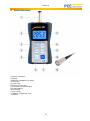
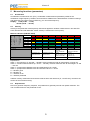
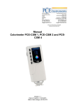
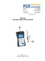
PCE Americas Inc.
711 Commerce Way
Suite 8
Jupiter
FL-33458
USA
From outside US: +1
Tel: (561) 320-9162
Fax: (561) 320-9176
[email protected]
PCE Instruments UK Ltd.
Units 12/13
Southpoint Business Park
Ensign way
Hampshire / Southampton
United Kingdom, SO31 4RF
From outside UK: +44
Tel: (0) 2380 98703 0
Fax: (0) 2380 98703 9
[email protected]
www.pce-instruments.com/english
www.pce-instruments.com
Manual
Vibration Meter PCE-VT2700
Version 2.0
Date of creation: 17.03.2015
Date of last change: 22.04.2015
Manual
Contents
1
Introduction ............................................................................................................. 3
2
Safety notes ............................................................................................................. 3
3
Specifications .......................................................................................................... 3
4
System description ................................................................................................. 4
5
Measuring functions (parameters) ........................................................................ 5
5.1
Acceleration ................................................................................................................................ 5
5.2
Velocity ....................................................................................................................................... 5
5.3
Displacement .............................................................................................................................. 5
6
Instructions.............................................................................................................. 6
6.1
Measurement .............................................................................................................................. 6
6.2
Battery replacement ................................................................................................................... 6
7
Further information on vibration measurement ................................................... 6
8
Disposal ................................................................................................................... 7
9
Contact ..................................................................................................................... 7
9.1
PCE Instruments UK .................................................................................................................. 7
9.2
PCE Americas ............................................................................................................................ 7
2
Manual
1
Introduction
Thank you for purchasing a vibration meter PCE-VT2700 from PCE Instruments.
This vibration meter is perfectly suitable for maintenance as it tests vibrating parts, machines and
equipment easily and quickly. With the PCE-VT2700, you can measure acceleration (m/s²), displacement
(mm), frequency (Hz, F) as well as velocity (RPM). This means that you can detect and trace imbalance
easily and reliably and avoid bearing damage by localising the source of undesirable vibration. By means
of an integrated RS-232 interface, you can transfer data directly from the meter to a PC. In addition to the
device, the delivery includes two measuring tips, a sensor, a magnetic plate, a carrying case and this
manual. An ISO calibration certificate is optionally available.
2
Safety notes
Please read this manual carefully and completely before you use the device for the first time. The device
may only be used by qualified personnel and repaired by PCE Instruments personnel. There is no
warranty of damages or injuries caused by non-observance of the manual.
- The device may only be used in the approved temperature range.
- The case should only be opened by qualified personnel of PCE Instruments.
- The instrument should never be placed with the user interface facing an object (e.g. keyboard side on a
table).
- You should not make any technical changes to the device.
- The appliance should only be cleaned with a damp cloth / use only pH-neutral cleaner.
This manual is published by PCE Instruments without any guarantee.
We expressly point to our general guarantee terms which can be found in our general terms of business.
If you have any questions please contact PCE Instruments.
3
Specifications
Measurement range
Resolution
Accuracy
Frequency range
Display
Interface
Battery
Operating conditions
Dimensions
Weight
acceleration
0.1 … 400.0 m/s² (Peak)
velocity
0.1 … 400.0 mm/s (RMS)
displacement 0.001 … 4.000 mm (P-P)
revolutions
5 … 100.000 rpm
0.1 m/s²; 0.1 mm/s; 1 µm, 1 rpm
± 5%
acceleration
10 Hz … 10 kHz
velocity
10 Hz … 1 kHz
displacement 10 Hz … 1 kHz
4-digit LC display,
value last measured is displayed
RS-232
4 x 1.5 V AAA batteries
battery life up to 4.5 hours at continuous operation
0 … 50 °C, < 90% RH
124 x 62 x 30 mm
240 g
3
Manual
4
System description
1) Sensor connection
2) Display
3) METRIC / IMPERIAL key (units)
4) HOLD key
5) Volume key
6) Earphone connection
7) Connection for RS-232 cable
8) FUNCTION key
9) FILTER key
10) On / off key
11) Battery compartment cover
12) Sensor
4
Manual
5
Measuring functions (parameters)
5.1
Acceleration
Acceleration is measured in m/s² (F/s²). Acceleration measurement is particularly useful for the
localisation of high-frequency vibration and is therefore suitable for the determination of faults in bearings
and gearboxes. By means of the FILTER key, you can set the frequency.
Display: 1 kHz (10 Hz … 1 kHz)
10 kHz (10 Hz … 10 kHz)
5.2
Velocity
Velocity is the parameter most frequently used and is applied to vibration measurement in line with ISO
2372, BS 4675 and VDI 2056 ISO 10816. Velocity is measured in mm/s (inch/s).
Base
Description
Group
Vibration velocity
mm/s RMS
10 – 1000 Hz n ˃800
min -1
(1– 1000 Hz n ˃120
min -1)
Machine vibration (DIN ISO 10816)
11.00 … ∞
7.10 … 11
4.50 … 7.10
3.50 … 4.50
2.80 … 3.50
2.30 … 2.80
1.40 … 2.30
0.0 … 1.40
hard
stretch
pumps ˃ 15 kW
hard
stretch
pumps ˃15 kW
multiblade rotor
with direct drive
multiblade rotor with
separate drive
4
3
hard
stretch
medium-sized
machines
15 kW ˂P˂300 kW
motors
160 mm ˂H˂315 mm
(≈6.30" ˂H˂12.40")
2
hard
stretch
big machines
300 kW ˂P˂50 MW
motors
315 mm ˂H
(≈12.40" ˂H)
1
Explanations:
Class 1 – big machines (P: 300 kW … 50 MW), electrical machines with an axle height h of ≥315 mm
Class 2 – medium-sized machines (P: 15 kW … 300 kW), electrical machines with an axle height h of 160
… 315 mm
Class 3 – pumps with multiblade rotors and separate drive P ˃15 kW
Class 4 – pumps with multiblade rotors and und direct drive P ˃ 15 kW
A – vibration good
B – vibration ok
C – vibration not ok
D – vibration prohibited
Vibration velocity measurements should be made in three axis directions (X, Y and Z axis), vertical to the
surface of the machine housing.
5.3
Displacement
Due to its good low-frequency response, this parameter is generally used for low-speed machines. The
unit of measurement for this parameter is mm.
5
Manual
6
Instructions
6.1
Measurement
Connect the sensor you have chosen to the device. Switch on the device by means of the Power key and
place the sensor at the object to be measured. For even surfaces, the magnet included in the delivery
content is very suitable. By means of the function key “FUNC.”, you can select the measurement function
which is either acceleration measurement (m/s²), velocity measurement (mm/s), displacement
measurement (mm), frequency measurement (Hz F) or revolutions measurement (rpm). To make a
selection, press the “FUNC.” Key several times until the desired measurement function is displayed. By
pressing the “HOLD” button, you can hold the maximum value of your measurement. “MAX” will appear in
the upper area of the display. You can deactivate this function by pressing “HOLD” again. The “METRIC /
IMPERIAL” key is used to set the units. For acceleration measurement, the units m/s² and F/s² are
available, for velocity measurement, you can select inch/s or mm/s and for displacement measurement,
the units mm and mil can be selected. When you work with headphones, you can control the volume (1 …
8) by pressing the “VOL” key several times until the desired value is indicated in the display. If machines
or bearings are operated under the same circumstances, you can use this device to carry out reference
measurements. By analysing these data, irregularities of the individual machines can be detected to
recognise possible faults at an early stage. Make sure that these measurements are always carried out at
the same spots in order to achieve high accuracy.
6.2
Battery replacement
Switch off the device and remove the battery compartment cover. Remove the batteries and insert some
new ones (4 x 1.5 AAA batteries). Close the battery compartment cover.
7
Further information on vibration measurement
Vibration measurement provides reliable information that allows conclusions regarding the mechanical
condition of a machine or product. Ideally, a machine has very little or no vibration as this indicates that
the motor as well as the peripheral devices such as gears, fans, compressors and other devices are
sufficiently balanced and aligned and correctly installed. In practice, a high percentage of installations are
far from ideal which is due to incorrect alignment and balancing and results in higher strain on loadbearing parts like bearings. This causes high strain on and wear of important parts and thus inefficiency,
heat generation and production downtime. Of course, this normally happens at the most inconvenient and
economically most inappropriate time and causes expensive production losses. Vibration increases as
wear and deterioration of mechanical parts rises. By regularly controlling the vibration of faultless
mechanical parts, you can detect deteriorations before they cause problems. This means that you are in a
position to order replacement parts in time and maintenance work must only be carried out when
required. This is to avoid expensive and unnecessary stocks of replacement parts, which brings financial
advantages. Unanticipated interruptions cause production downtime. Defective machines and equipment
are often repaired in a hurry so that production can be continued as soon as possible. Regardless of how
precisely the staff works, it is not always possible under these circumstances to carry out repairs
correctly. This can in turn lead to machine and equipment downtime again. A predictive maintenance
schedule according to which important factors like vibration are measured on a regular basis does not
only allow you to reduce interruptions in production but also to make maintenance work more effective.
This increases product quality and productivity.
The term “trend” is very important to know in connection with vibration measurement. A trend indicates
how a monitored parameter behaves over time. If vibration measurements have been made and plotted
over a certain period of time, the resulting graph shows the progress or the deterioration of a certain
machine. Immediately after installation, it is possible that the vibration level decreases slightly as the
machine is run in, no matter if the machine is new or was repaired. This period is followed by the normal
operating time of the machine, which is a longer period of time during which the vibration level does not
change. The next period will be one during which the vibration level will increase due to wear of machine
components before the machine eventually stops working. Such a trend enables the engineer to predict
the approximate downtime, to maximise the benefit of the machine, to order replacement parts and at the
same time to adapt maintenance work to the production schedule.
6
Manual
8
Disposal
For the disposal of batteries, the 2006/66/EC directive of the European Parliament applies. Due to the
contained pollutants, batteries must not be disposed of as household waste. They must be given to
collection points designed for that purpose.
In order to comply with the EU directive 2012/19/EU we take our devices back. We either re-use them or
give them to a recycling company which disposes of the devices in line with law.
If you have any questions, please contact PCE Instruments.
9
Contact
If you have any questions about our range of products or measuring instruments please contact PCE
Instruments.
9.1
PCE Instruments UK
By post:
PCE Instruments UK Ltd.
Units 12/13 Southpoint Business Park
Ensign Way, Southampton
Hampshire
United Kingdom, SO31 4RF
By phone:
02380 987 035
9.2
PCE Americas
By post:
PCE Americas Inc.
711 Commerce Way
Suite 8
Jupiter
33458 FL
USA
By phone:
561 320 9162
7