1
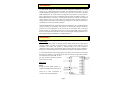
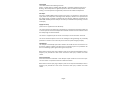
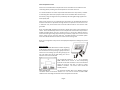
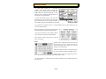
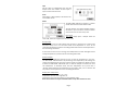
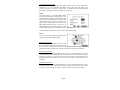
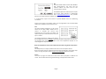
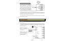
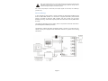
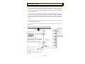
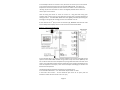
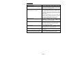
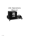
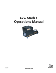
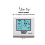
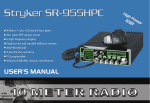
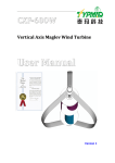
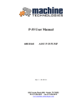
 EASY ZONE TOUCH Installer Manual It is recommended that this manual be used in conjunction with the user manual. Ver 1.0 Index Index 2 Introduction 3 Installation 3 System Design 3 Relay Card 3 Wall Controller 5 Installer Menu 6 Wiring Examples 10 Basic Wiring 10 Advanced Wirings 11 Application Notes 12 Specifications 15 Page 2 Introduction The EASY ZONE TOUCH is a zone control system designed to complement a heating cooling or air conditioning system of almost any manufacture that does not have zoning capability by adding active or passive zone control for up to 6 Zones. The EASY ZONE TOUCH does not interfere with the operation or electronics of any system nor does it affect the warranty of any heating & cooling system if installed correctly. The EASY ZONE TOUCH is a “parasitic” control system; it does not override any heating & cooling system control or interfere with any heating & cooling system operation. It simply monitors and waits for the heating & cooling to turn on and then directs the conditioned air to the zone with the demand. The EASY ZONE TOUCH can re‐broadcast the zone temperature to a suitable heating & cooling controller if compatible. This permits the heating & cooling controller to measure the zone temperature in the zone under control rather than in one fixed distant location. So, if the bedroom zone is on, then the heating & cooling controller will “see” the bedroom temperature and turn the heating & cooling equipment on or off to maintain the set temperature in the bedroom zone. Installation System Design Great effort has been taken to making the EASY ZONE TOUCH zone control system intuitive, reliable and easy to install. Using a common sense approach to the installation will ensure this product is installed easily and to the customer’s satisfaction. Please read and understand this instruction manual so that installation, testing and commissioning process is undertaken in an efficient and effective manner. It is recommended that when designing the duct layout, that all zones are connected directly to the supply air, and that all branch sizes are similar in length where possible and oversized by at least 15% to carry the extra air flow that may be present when zones are closed. Relay Card Wiring Wiring the EASY ZONE TOUCH is a simple and straight forward procedure. There are 6 basic connections to consider, each is detailed below. Page 3 Status LEDS These LEDS indicate the following functions. Power – system power is available. Slow blink OK ‐ rapid blink communications error. Heating – Duct temperature is significantly warmer than the ambient temperature. Cooling – Duct temperature is significantly cooler than the ambient temperature. 24V Input. Connect a suitable 24VAC power supply to this input. It is important to note that this input powers all components including all zone dampers; therefore it is important that the power supply is capable of switching all zone dampers. (200mA is needed for the EASY ZONE TOUCH plus each damper can draw up to 350mA each depending on brand of damper) Supply Air Temp (This sensor is supplied and must be fitted). This input monitors the discharge air temperature of the heating & cooling system and is used to open all zones if this temperature exceeds set limits. It is also used to control the damper logic in advanced mode. This sensor is supplied as part of the kit. If necessary it can be extended – 10m max. This sensor should be place as close to the heating & cooling discharge as practicably possible to in order to ensure accuracy and to react to system changes promptly. Spill Damper This damper automatically opens when installer set number of zones are closed. It can be used to supply a common zone when there is capacity to spare or as protection for the air conditioning system against closing too many zones. Both a RJ12 connector (for plug in dampers) and a three way terminal block (for wire in dampers) are provided for zone motor connection drive open, common and drive closed. Zone input/output Each of the 6 zones is fitted with a zone damper output as well as a zone sensor input. The zone sensor is required for Normal or Advanced modes. Both a RJ12 connector (for plug in dampers) and a three way terminal block (for wire in dampers) are provided for zone motor connection drive open, common and drive closed. Page 4 Zone Temperature sensor Each zone can be fitted with a temperature sensor that will be re‐transmitted to the controlling device providing accurate temperature control for that zone. It is recommended to use Smart Temp thermostats with Smart Temp sensors, however if controlling other brands of equipment that cant be controlled with a Smart Temp thermostat, using the original sensors provided by the heating & cooling supplier will work equally well. Smart Temp sensors are non polarised two wire devices. A recommended maximum distance of 20 meters is permitted. If longer distance is required or the sensors are run in electrical noisy environments then screened cable should be used and the drain grounded. Note: The EASY ZONE TOUCH wall controller is fitted with a Smart Temp temperature sensor. This is automatically used for zone 1 temperature measurement. If you wish to disable this fitted sensor and use a remote sensor or a sensor of a different value to match the heating & cooling equipment being controlled, simply wire a sensor into the Zone 1 sensor input on the main relay card. The INFO window in the installer option menu will indicate whether the local or remote sensor is being used. Note, if not using Smart Temp sensors the displayed temperature readings may not be accurate. Wall Controller Open the EASY ZONE TOUCH wall controller by placing a flat blade screwdriver in the slot on the bottom of the thermostat case and pushing in gently inwards to release the case locking clip and then gently pry the two case half’s apart at the base taking care not to twist the case and crack the LCD. The 4 terminals marked “1 2 3 4” on the EASY ZONE TOUCH must connect to the corresponding terminals on the wall controller. 4 core screened cable should be used for this with a 0.2mm or larger diameter conductor. The screen drain should be suitably earthed. The terminals marked “AB” are for Modbus network connection while the terminals marked “TT”” are used to connect the EASY ZONE TOUCH to the controlling thermostats remote temperature terminals. Page 5 Installer Menu The EASY ZONE TOUCH has a concealed installer menu where system settings and safeties can be adjusted to ensure the EASY ZONE TOUCH is matched perfectly to the demands of the heating & cooling system as well as the users requirements. To enter the installer menu, press and hold the status bar for 10 seconds. You may get better results if you use your fingernail rather than a finger tip given the relatively thin status bar. The functions and settings shown in reverse (white text on black boxes) are the currently selected items. After pressing the status bar for 10 seconds, the LCD will change and show the Installer Menu. There are 9 submenus in the installer options, these options are explained in detail below. Press “Back” or wait 30 seconds to exit this menu at any time. Name Select the zone number from the column on the left and then the zone name you wish to associate with that zone number. Zone 1 in this example is named “Master”. There are 2 pages of names, “next” permits you to scroll to the second page of available names. Selecting “Not” Used” will disable that zone. This is handy when the installation requires less than 6 zones. The Zone numbers in the left column correspond with the zone numbers printed on the relay card. Page 6 Spill Set this value to automatically open the spill damper when the number of zones open is equal or lower than this value. Units Select deg C or deg F display in all relevant user and installer menus. Mode The EASY ZONE TOUCH can operate in 3 similar modes with variations within these modes. The spill function and system safeties apply to all modes so you can limit the minimum number of zones the user can close at any time. Basic mode This mode simply opens a damper when the zone is ON, and closes it again when the zone is off. Normal mode In this mode the user can select which zones are open or closed just as in basic mode described above, but it can also select which zone temperature is “sent” to the controlling thermostat so that the controlling thermostat measures the temperature in the zone being conditioned. If more than one zone is set to sensing, those temperatures are then averaged and the average temperature is passed onto the controlling thermostat. Advanced Mode Advanced mode additionally permits the user to limit the temperature in any zone. The EASY ZONE TOUCH does this by monitoring zone temperature, the heating and cooling set temperature for that zone and the supply air temperature. Based on these 3 factors the EASY ZONE TOUCH will open or close the damper to maintain the zone set temperature. In advanced mode, the zone temperature of any zone that is “Sensing” will be passed to the thermostat. Any zone that is “Off”, “On” or “Active” will not pass the zone temperature to the controlling thermostat. Display Zone Temperature. Selecting “Yes” will show the zone temperature of each zone regardless of whether the zone is Off, On, Sensing or active. Default is OFF. Note: this function can only be used when Smart Temp Zone sensors are used. Page 7 Thermostat output enabled. If the project does not require EASY ZONE TOUCH to pass zone temperature information on to the controlling thermostat select “NO” from this option. This removes the need to maintain a sensing zone, normally essential if the controlling thermostat is relying on a remote temperature sensor value. Safety The safety system on the EASY ZONE TOUCH monitors the discharge air temperature of the heating & cooling system via the supplied “Duct Sensor” and if a temperature above the Heat alarm temperature is measured or below the cooling alarm temperature is measured the EASY ZONE TOUCH will open all zones in an attempt to improve air flow through the indoor coils hopefully bringing the coil temperature to a safer value. The user will be informed of this situation via a status bar message. Zones The zone menu options will vary based on other settings within the EASY ZONE TOUCH. Minimum open zones. This sets the minimum number of open zones (not including the spill) that must be kept open. If the user tries to close too many zones they will get an alert on the status bar indicating that they must maintain a minimum number of open zones at all times. Maximum Active Zones As an active zone can automatically close based on room & set temperature this zone is considered by the EASY ZONE TOUCH as a “Closed Zone”. So that the user cannot set all zones as active (as in theory all zones can close as they all reach the Zone set temperature) this menu option can set a limit on the number of active zones the user can apply. Minimum Sensing zones The sensing zone reports the zone temperature to the controlling thermostat. In most installations where normal or advanced mode is selected it is important that at least one zone is set at “Sensing” at all times. This menu option provides this protection. Page 8 Net The EASY ZONE TOUCH is fitted with Modbus RTU communications. This menu sets the network address and baud rate for this communications protocol. The Modbus objects list obtained upon request from Smart Temp Australia or downloaded from www.thermostat.com.au and provides detail on the communications capability of the EASY ZONE TOUCH. It is beyond the scope of this manual to provide Modbus data and networking connections. Custom zone names and company names can be programmed into the EASY ZONE TOUCH via this Modbus communications port. Info This page provides information on the current status of the EASY ZONE TOUCH and its sensors. It provides the current zone temperature (if zone sensors are fitted), the system temperature and whether the zones are open or closed. The average temperature shown on this page is the average of the current “Sensing” zones and only when using Smart Temp sensors. This Average value should be the same as the room temperature display on the controlling Smart Temp thermostat. Note: the temperature sensor data is ONLY accurate when using Smart Temp sensors Sensor This will permit you to adjust / calibrate the various zone and system sensors. Note: this should never be needed and should only be considered if using Smart Temp sensors. If using third party sensors under no circumstances adjust these values. Screen Touch the top right and lower left of the screen when prompted to calibrate the screen. This should be done during commissioning of the system for best results. Page 9 Temperature Sensor switching logic The EASY ZONE TOUCH key advantage over other add on zone management system is the ability to measure the zone temperature and faithfully reproduce it to the controlling device. This way, regardless of brand the EASY ZONE TOUCH can accurately manage the space temperature provided the sensors measuring the space match the profile of the controlling device; i.e. are of the same brand. The EASY ZONE TOUCH permits the user to select which zone the temperature is monitored by selecting “Sensing” zones. If more than 1 sensing zone is selected the EASY ZONE TOUCH averages these temperatures. The average value of all “Sensing” can be shown in the info screen in the installer menu described previously. Wiring Examples (note – these examples only show zone 1 damper and sensor) Basic Wiring The EASY ZONE TOUCH in its most basic form will simply open and close 24V dampers on command from the user. It has no temperature monitoring function nor does it rely on feedback of equipment status. However, the supplied supply air sensor is provided and must be fitted. Dampers can be hard wired, or if preferred dampers fitted with RJ12 can be used. Wiring to the wall controller should be 4 core screened cable with conductor diameter of 0.2mm or greater. Page 10 Note, If you intend to wire two or more zone dampers to the same zone output of the EASY ZONE TOUCH be aware that some brands of dampers feedback voltage whilst in motion causing the dampers to continuously move. Use a Smart Temp damper or check with your damper supplier to ensure they are suitable for parallel wiring. Advanced Wirings In this example all control wiring is shown including the thermostat feedback wiring from the EASY ZONE TOUCH “TT” Terminals to a typical thermostat. (A thermostat output is provided on both the wall controller and main control card to permit flexibility of wiring – both these outputs provide the same value and only ONE should be used). The supply air discharge sensor is shown, which is required for advanced mode and to provide equipment feedback protection. Thermostat to heating & cooling equipment wiring is shown as a guide only; you should consult your equipment and thermostat manual for specific control wiring information. Page 11 Application Notes Many heating & cooling systems including variable capacity ducted systems (typically named Inverters) must use their own thermostat controller to control their set point and operational mode, however some brands are fitted with a remote temperature sensor input; this sensor is typically placed in the return air duct to get an average of the space temperature. Wiring this input into the EASY ZONE TOUCH and then placing temperature sensors of the same brand in each of the zones will permit these sensor values to be digitally switched into the EASY ZONE TOUCH. Now, when you select a Zone you can bring that zone temperature to the Air conditioning system controller for managed temperature control. This permits you to zone a system not normally capable of zoning and without invalidating system warranties. There are two ways to successfully interface with third party systems not normally able to zone. Option 1 – digitally switch third party temperature sensors Page 12 In this example a brand “X” inverter is used, the return air sensor input on the inverter is connected to the thermostat output on the EASY ZONE TOUCH. Then brand “X” temperature sensors are placed into each of the zones. When a zone is switched to “Sensing” by the user the brand “X” sensors are digitally switched to the return air sensor input on the inverter. Think of having the brand “X” return air sensor on a long lead and having your customer take it from room to room with them as they wish to change temperature sensing locations. The EASY ZONE TOUCH does this digitally, faithfully reproducing the readings (or average of the readings) as zones are switched on or off. As this method uses 3rd party sensors of unknown type, NORMAL mode must be used and the temperature display values cannot be used and should be disabled. Option 2 – limit zone temperatures In this example there is no direct connection between the inverter heating & cooling systems and the EASY ZONE TOUCH. Using a Smart Temp zone sensor (PN RS‐1) the user is able to limit each zones temperature by using Advanced mode and active zone control. This mode will compare the zone temperature, the supply air temperature and zone set temperature and open / close the zone damper accordingly to maintain the desired zone temperature. The following settings should be confirmed in the installer menu. In the Control mode section – set “Thermostat output enable” to “OFF”. In the Zones menu section ‐ set the minimum open zones to “0” (zero) and the maximum number of active zones is set to “6” (six). Page 13 Error Messages Message Memory chip Failure Explanation This is a critical fault – power down reset and monitor. If the fault returns the EASY ZONE TOUCH is terminal and should be replaced. If this message is appearing often check the zone safely threshold settings (under the safety menu in the installer options). Increase the number of zones that must be open (increase minimum zone setting) or change the spill setting to ensure it will open at a larger number. If using adjustable dampers such as Smart Temp STB dampers, set the minimum closed value on all zone to permit a bleed past when the zone is closed. Fit an additional barometric by‐pass damer. The sensor monitoring the air conditioning duct temperature is missing or faulty. Replace the sensor, check for loose connections. Check the wiring between the EASY ZONE TOUCH wall controller and relay card. Ensure the cable used is screened and the screen is properly earthed. Power down reset and monitor A zone temperature sensor is missing or faulty. Check the wiring and sensor. If long sensor runs are used (>30M) use screened single pair wire. Check wiring of the zone motor for reversed connections Any fault detected will cause the EASY ZONE TOUCH
to enter protection mode and open all zones System temperature is too low System temperature is too high System Sensor Fault Communication breakdown Zone Sensor Fault Zones open when they should close etc All zones are open and will not respond to commands from the wall controller Page 14 Notes: Page 15 Specifications Wall Controller Input Voltage Operating Temperature Operating RH Storage Temperature Size Display Size Backlight Display type Memory type Communications 24VAC 50/60 Htz +/‐ 15%. 0‐50C (32 to 122F). 0‐95% (non condensing). 0‐65C (32 to 150F). 113 x 103 x 23mm. 69.5 x 46.3mm. Blue EL (On for 30 seconds after last button press). 240 x 320 pixel FSTN touch panel. Non volatile – Settings do not require battery backup. Modbus RTU 9600 baud 1 stop bit 1 start bit no parity. Main Relay Card Input Voltage Operating Temperature Operating RH Storage Temperature Size Memory type Zone / Spill Relays Zone Sensor input AC sensor input 24VAC 50/60 Htz +/‐ 15%. 0‐50C (32 to 122F). 0‐95% (non condensing). 0‐65C (32 to 150F). 110 x 200mm. Non volatile – Settings do not require battery backup 24V @ 2amps max 2 to 50K (10KTypeII NTC required for advanced mode). 10KTypeII NTC only (Smart Temp PN Rs‐D) Common Approvals Warranty FCC (Part 15) (pending), C‐tick. 3 years RTB. Great care has been taken in the preparation of this manual. Smart Temp Australia P/L takes no responsibility for errors or omissions contained in this document. It is the responsibility of the user to ensure this controller, or equipment connected to it is operating to their respective specifications and in a safe manner. Due to ongoing product improvement Smart Temp Australia P/L reserves the right to change the specifications of the EASY ZONE TOUCH (or its components) without notice. All rights reserved. © Smart Temp Australia P/L 2009 Intellectual rights apply. Page 16