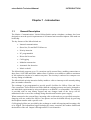
1
PLFUR6ZLWFK 7(&+1,&$/0$18$/ Version 1.1.12- firmware © Marine Communications Limited 1998 Marine Communications Limited 59 Bownham Park, Rodborough Common, Stroud, Glos GL5 5BZ England Telephone: Fax: Email: Web: +44 (0)1453 873399 +44 (0)1453 873344 [email protected] http://www.marinex.co.uk November, 1998 PLFUR6ZLWFK7HFKQLFDO0DQXDO &217(176 CONTENTS &KDSWHU Introduction ...........................................................1 1.1 1.1.1 1.1.2 1.1.3 1.1.4 General Description ........................................................................................... 1 Specifications.................................................................................................... 3 Basic Specifications.......................................................................................... 3 Environmental Specifications........................................................................... 4 Power Supply.................................................................................................... 4 1.2 Requirements ..................................................................................................... 4 1.3 MicroAid ........................................................................................................... 4 1.4 Extension Facilities ........................................................................................... 4 &KDSWHU Installation.............................................................5 2.1 Pre-Installation Checks...................................................................................... 5 2.2 Physical Installation........................................................................................... 5 2.3 Locating The Unit.............................................................................................. 6 2.4 Power Connections ............................................................................................ 8 2.5 Exchange Connections ...................................................................................... 8 2.6 2.6.1 RS232 Call Log Serial Interface Connections................................................. 10 Printer Data Format ........................................................................................ 11 2.7 2.7.1 Set Up Terminal Connections.......................................................................... 11 Terminal Data Format..................................................................................... 11 2.8 2.8.1 2.8.2 2.8.3 2.8.4 Engineering Checks ......................................................................................... 12 Installation Checks.......................................................................................... 12 Bell Check ...................................................................................................... 12 Extension Number Check ............................................................................... 12 Off-Hook (locked out) Extensions.................................................................. 12 &KDSWHU System Configuration......................................... 13 3.1 General............................................................................................................. 13 3.2 3.2.1 3.2.2 3.2.3 3.2.4 3.2.5 Factory Configuration...................................................................................... 14 First Dialled Digit ........................................................................................... 14 Dial 6 Access .................................................................................................. 14 Dial 9 Access .................................................................................................. 14 * (Star) Features From Dial Tone ................................................................... 15 Features from Recall....................................................................................... 15 i &217(176 PLFUR6ZLWFK7HFKQLFDO0DQXDO 3.2.6 3.2.7 3.2.8 3.2.9 * (Star) Features from Recall.......................................................................... 15 Features from Recall – Engaged or NU.......................................................... 15 * (Star) Features from Engaged...................................................................... 15 * (Star) Features from Ringing....................................................................... 15 3.3 3.3.1 3.3.2 Changing The Configuration........................................................................... 16 Engineering Facility Mode ............................................................................. 16 Engineering Function List .............................................................................. 17 3.4 Distinctive Ring Style...................................................................................... 19 3.5 Single ‘9’ Tie Line Access .............................................................................. 19 3.6 Tie Line Gain Settings..................................................................................... 19 3.7 3.7.1 3.7.2 3.7.3 Timings............................................................................................................ 19 Variable 2nd Designated Number access ........................................................ 19 DISA Activation ............................................................................................. 20 Release of tie lines.......................................................................................... 20 3.8 3.8.1 Pin Number...................................................................................................... 20 Printing PIN numbers ..................................................................................... 20 3.9 Phone Reset Facility........................................................................................ 20 &KDSWHU Maintenance ........................................................ 21 4.1 Routine Maintenance....................................................................................... 21 4.2 Battery Replacement........................................................................................ 21 4.3 Fault Finding ................................................................................................... 22 4.3.1 All Telephones Dead ...................................................................................... 22 4.3.2 One Telephone Dead ...................................................................................... 22 4.3.3 All Telephones Live, But No Dial Tone......................................................... 22 4.3.4 One Telephone Live, But No Dial Tone......................................................... 23 4.3.5 Wrong Extension Obtained When Dialling.................................................... 23 4.3.6 Telephone Always Busy When Dialled.......................................................... 23 4.3.7 Telephone Always Unobtainable When Dialled ............................................ 23 4.3.8 All Telephones Fail to Ring, But Ring Tone can be Heard by Caller ............ 24 4.3.9 One Telephone Fails to Ring, But Ring Tone can be Heard by Caller........... 24 4.3.10 Intermittent Dial Tone .................................................................................... 24 4.3.11 Crosstalk on Conversation.............................................................................. 24 4.3.12 Unable to Obtain Shore Line. ......................................................................... 25 4.3.13 Incoming Call Not Received .......................................................................... 25 4.3.14 Call Logging Not Outputting Data ................................................................. 25 4.3.15 Loss or Change of Facilities ........................................................................... 25 Appendix A - Factory Configuration......................................... 27 ii PLFUR6ZLWFK7HFKQLFDO0DQXDO ,1752'8&7,21 &KDSWHU Introduction 1.1 General Description The Marine Communications Limited MicroSwitch marine telephone exchange has been designed to meet the special requirements of all internal and external telephone calls made on board ship. The key features of the MicroSwitch are: • Internal communications • Shore line, PA and SATCOM access • Priority intrusion • PC programmable • Direct dial in and out • Call logging • Modular construction • Automatic fax detection • Music on hold The MicroSwitch supports up to 32 extensions and 8 external lines, enabling connections to shore lines, SATCOM and Public Address lines. Facilities are available to enable a maximum of 4/8 connection circuits to be made at any time. The circuitry is enclosed in a compact case for easy fitting to bulkheads. The MicroSwitch priority intrusion facility enables a caller to interrupt a call currently taking place on another extension. The exchange is pre-programmed to provide specific facilities for Officer Class and Crew Class extensions. These facilities are held within the exchange memory and can be changed to suit individual requirements by using a telephone or an IBM PC (or compatible). The memory is provided with its own battery support and any changes made to the set-up will be maintained in the event of the exchange being disconnected from the power supply. When connected to the external lines, incoming calls are directed to a pre-specified extension. Outgoing calls are enabled for Officer Class phones and can be dialled directly by prefixing the telephone number with a specific code. Call-logging facilities are provided by the exchange to enable all outgoing and incoming calls to be logged. The information logged includes the source extension, the number dialled and the duration of the call. Output is through an RS232 serial interface. 1 ,1752'8&7,21 PLFUR6ZLWFK7HFKQLFDO0DQXDO Future expansion and servicing of the exchange is carried out simply by adding or replacing plug-in modules. To assist with maintenance and fault finding, a number of indicators are provided on the modules to show the status of the exchange and the extension lines. MicroSwitch will detect an incoming fax call tone and automatically transfer it to the designated extension. In the event of a power failure external lines are connected directly to specified extensions. Please note that satisfactory performance cannot be guaranteed for every allowed combination of host and subsidiary apparatus, in particular, certain modern electronic phones when set to LD mode may not be recognised correctly. CAUTION microSwitch is designed for use on board ships. It may not comply with specific statutory requirements such as EMC/PTT standards for use on land based applications. 2 PLFUR6ZLWFK7HFKQLFDO0DQXDO 1.1.1 Specifications 1.1.2 Basic Specifications ,1752'8&7,21 Capacity (maximum) 32 internal extensions (in blocks of 8). 8 external lines (in blocks of 2). Maximum of 8 circuits can be made at any time. External Connections Shore lines, SATCOMs, P.A. lines External Signalling Push-button dual tone multi-frequency (DTMF) preferred. Loop disconnect LD (Impulse) can be used, but with reduced facilities. Battery life programme memory 5 years minimum Frequency Range 300Hz to 5Khz at 3dB points Cabling 2 wire throughout Input Voltages 24V D.C. +/-10%, 2A peak, 1A nominal average. 250 mV ripple. Indicators show if the D.C. supply is available. Fuses - DC 5A anti surge 20mm MTBF 10,000 hours (fully loaded system) MTTR 30 minutes Dimensions 320mm (H) x 390mm (W) x 150mm (D) Weight Approx. 5Kg 3 ,1752'8&7,21 1.1.3 PLFUR6ZLWFK7HFKQLFDO0DQXDO Environmental Specifications The MicroSwitch exchange has been tested and meets with Lloyds Register ENV2 type approval requirements. 1.1.4 Temperature Operating Storage 0 to +55 deg C 0 to +70 deg C Humidity 5 to 95% relative humidity Vibration 1.0mm amplitude at 2 to 13.2Hz 1g at 13.2 to 100Hz Power Supply It is recommended that the microSwitch is not powered directly from the ship’s emergency supply as this will increase the background noise heard on the extensions. 1.2 Requirements An IBM PC (or compatible) with a serial interface and the microAid program or a DTMF telephone are required to program a MicroSwitch exchange. 1.3 MicroAid microAid is a software utility to enable you to reconfigure the MicroSwitch. Full details about microAid are provided in the microAid help file which is available from Marine Communications Limited at the address given in the front of this handbook. 1.4 Extension Facilities The MicroSwitch extensions are grouped into two user categories: • Category A - Officer Class extensions • Category B - Crew Class extensions In addition there are Engineering facilities which are only available through a PIN access code. The Officer Class and Crew Class facilities are described in the MicroSwitch User Manual; the Engineering facilities are described in this manual. 4 PLFUR6ZLWFK7HFKQLFDO0DQXDO ,167$//$7,21 &KDSWHU Installation 2.1 Pre-Installation Checks Before unpacking the MicroSwitch exchange, check the packing carton for signs of damage. Any damage to the carton should be reported to the supplier before proceeding. Open the carton, carefully remove the contents and check for any signs of mechanical damage. Check that the documentation is present: MicroSwitch User Manual 2.2 Physical Installation The MicroSwitch should be installed in a location away from electrical noise and excess vibration. Where possible the equipment should be located in a well ventilated area where it will not be adversely affected by salt water and extremes of heat. When locating the unit make sure you can access the modules and cable connectors. Clearance should be allowed on each side of the case to avoid contact with neighbouring equipment through vibration and shock. The unit is supplied with the lid unsecured. This is to allow you to fit the lid so that it opens either right handed or left handed depending on which is most convenient. In Figure 2-2 the lid is hinged to the left. 5 ,167$//$7,21 2.3 PLFUR6ZLWFK7HFKQLFDO0DQXDO Locating The Unit Figure 1 identifies the cabinet dimensions. Please refer to these when you are locating the MicroSwitch in its permanent position. Figure 1 Cabinet Dimensions Loosely fit the top screw and manoeuvre the cabinet so that the screw slots into the top hole on the rear of the cabinet. There is a covering cap on the hole for the top screw which needs to be removed in order to place the unit and replaced once the unit has been placed and the screw tightened. The bottom two screws are accessed from the front of the cabinet. See Figure 2 on the next page. 6 PLFUR6ZLWFK7HFKQLFDO0DQXDO ,167$//$7,21 F D A 2 1 3 4 5 E G B C Figure 2 MicroSwitch Unit - Front View In the diagram, above the MicroSwitch is shown with the panel removed from the lower section of the unit to show B and C screw positions. This section houses the terminal strips, the power terminal block and the printer connection. To open the door of the unit you need to undo screws D and E. Rotate each screw one quarter turn anti-clockwise and release the catches. Once the unit has been put in place all three screws A, B and C must be tightened firmly. To access B and C you need to remove the cover from the bottom panel of the unit. NOTE: If you have more than 16 extensions then you need to remove one pair of modules (Pair 4 in Figure 2-2), to access screw A. To unplug the modules you need to remove the top and bottom strips F and G by undoing the screws at either end of the strips. WARNING Failure to tighten screws a, b, c firmly may cause the unit to loosen from its mountings during continued vibration and so cause damage to the cabinet and/or the modules. 7 ,167$//$7,21 PLFUR6ZLWFK7HFKQLFDO0DQXDO Ensure that the exchange is securely sited and that all cables to the exchange are arranged tidily and secured such that they cannot pull the connectors out of the exchange. Check that all the modules are fully plugged into the chassis and correctly located in their card guides before applying power for the first time. A module could become loosened from the chassis if there was excessive vibration. Two metal strips F and G provide additional stability for the modules and must be fitted to prevent the modules from vibrating out of position. 2.4 Power Connections Power connection is via a two-way terminal block mounted in the lower right hand side of the bottom section of the MicroSwitch unit. When connecting to the terminals, the power leads should be pushed through from under the unit where there are a series of holes. (Remove the grommet from the relevant hole.) See Figure 3 below. Power Terminal RESET / PRINTER - - - - - - - - + 24 V D.C. Figure 3 Power Terminal Connections 2.5 Exchange Connections Connections between the exchange and the external equipment are through terminal screw type connectors. Refer to Figure 4 for the connection pattern. 8 PLFUR6ZLWFK7HFKQLFDO0DQXDO ,167$//$7,21 Figure 4 Exchange Connections 9 ,167$//$7,21 PLFUR6ZLWFK7HFKQLFDO0DQXDO Processor Board Power Board Switch Module Main Power Fuse Bias Fuse RS232 Computer Port 9 way D Ringing Fuse Extension LED’s Extension LED’s Ringing LED Always flashing Tie Lines No board in slot 1 ringing Shore Occupied Power Power Tie Lines ringing SATCOM Bias LED 12V LED Occupied 5V LED Figure 5 microSwitch LED’s This Figure 5 illustrates the position of the LED’s and fuses on the appropriate boards. The diagram shows one switch module but you may have up to four modules. The latest power boards do not have the Bias or Ringing fuses. 2.6 RS232 Call Log Serial Interface Connections These connections are provided by an orange two part screw terminal strip located at the bottom of the MicroSwitch. All the pins 1 to 8 are used with the exception of pin 6 which is unconnected. The wiring to a 9-way PC serial connector is shown in the table. An 8 pin connector is supplied with the unit. 10 PLFUR6ZLWFK7HFKQLFDO0DQXDO PIN SIGNAL ,167$//$7,21 PC 9 way 1 Signal Ground 5 2 Transmitted data from MicroSwitch 3 3 Received data to MicroSwitch 2 4 Ready To Send (RTS) - output from MicroSwitch 8 5 Clear To Send (CTS) - input to MicroSwitch 7 6 Not connected - 7 Reset 1 - 8 Reset 2 - *Connect Pins 7 and 8 together to reset MicroSwitch to user configuration. 2.6.1 Printer Data Format The RS232 call log interface is configured to operate at 9600 baud, no parity, 8-bit data and one stop bit. If hardware control (RTS/CTS) is not being used then Pins 4 and 5 should be connected together. 2.7 Set Up Terminal Connections The terminal used for setting up the MicroSwitch is connected to a 9-way ‘D’ socket on the front of the processor card. To access this connector, it is necessary to open the front panel. The wiring to a 9-way PC serial connector is also shown in the table below. PIN 2.7.1 SIGNAL PC 9 way 2 Transmit data from the microSwitch 5 3 Receive data to the MicroSwitch 3 5 0V 2 7 Ready To Send (RTS) - output from MicroSwitch 8 8 Clear To Send (CTS) - input to MicroSwitch 7 Terminal Data Format The terminal port is configured to operate at 9600 baud, no parity, 8-bit data and one stop bit. 11 ,167$//$7,21 2.8 Engineering Checks 2.8.1 Installation Checks PLFUR6ZLWFK7HFKQLFDO0DQXDO Once the equipment has been installed, the MicroSwitch exchange should be powered up and the indicator observed on the front panel to ensure that power is reaching the unit. Each installed board should have the power LED illuminated. A systematic check should now be made of all ‘in-service’ telephones to ensure that each telephone is capable of dialling another telephone and is capable of being dialled. The speech quality of each telephone should also be checked when each telephone is dialled. Having verified the basic operation of each telephone, one of the Officer Class telephones should be used to check the operation of each external line and to check that all the features are working It is recommended that no special programming of the MicroSwitch exchange should be performed until satisfactory operation of the complete system has been established. In the event of a fault being found during the installation checks, the following engineering checks should prove useful in identifying the cause. Further help can be obtained by referring to the Fault Finding section later in this document. 2.8.2 Bell Check If you lift the receiver, dial *6, then replace the receiver, the telephone should ring to enable the amplitude and operation of the bell to be checked. 2.8.3 Extension Number Check If you dial your own extension number a high pitched ‘busy’ ringing tone should be heard. 2.8.4 Off-Hook (locked out) Extensions A print out of all off-hook (locked out) extensions can be obtained from the call logging port by dialling 73 when in Engineering Facility mode. 12 PLFUR6ZLWFK7HFKQLFDO0DQXDO 6<67(0&21),*85$7,21 &KDSWHU System Configuration 3.1 General The MicroSwitch is supplied from the factory with a range of facilities already configured. The Crew and Officer class facilities are described in the MicroSwitch User Manual. Facilities requiring Engineering access mode are discussed in this manual. The default configuration can be modified to suit on-board requirements by using a program called microAid. The microAid software is available on a floppy diskette and is described in a separate handbook. Limited reconfiguration can be carried out using a security PIN number which allows access to the MicroSwitch system via a DTMF telephone. If you reconfigure the MicroSwitch exchange we recommend that you print a record of the new configuration details and keep them with this manual for reference. IMPORTANT You are strongly advised to ensure the satisfactory operation of the complete system as described in the installation checks before you implement any modifications to the factory configuration. 13 6<67(0&21),*85$7,21 3.2 PLFUR6ZLWFK7HFKQLFDO0DQXDO Factory Configuration The MicroSwitch exchange is supplied with the following configurations already defined: 3.2.1 First Dialled Digit 0 1 2 3 4 5 6 7 8 9 * # 3.2.2 + xx (00-99) +x (0-9) + xx (00-99) +x (0-9) + xx (00-99) +x (0-9) + xx (00-99) +x (0-9) +x or or or or Public address ‘65’ For 3 digit extension number For 2 digit extension number For 3 digit extension number For 2 digit extension number For 3 digit extension number For 2 digit extension number For 3 digit extension number For 2 digit extension number Hold numbers Public Address access Reserved Night Bell pick-up Outsides line access Star features Engineering Dial 6 Access A pin number may be required to be entered before the access digit. 1 2 3 4 5 6 7 8 3.2.3 Individual P.A. access number Individual P.A. access number Individual P.A. access number Individual P.A. access number Group P.A. access or ‘0’ access Group P.A. access Group P.A. access Group P.A. access Dial 9 Access A pin number may be required to be entered before the access digit. 2 3 4 5 6 7 8 9 14 SATCOM 1 SATCOM 2 SATCOM 3 Land 1 Land 2 Land 3 SATCOM hunt group Land hunt group PLFUR6ZLWFK7HFKQLFDO0DQXDO 3.2.4 6<67(0&21),*85$7,21 * (Star) Features From Dial Tone *2 *3 *5 *6 *8 *9 3.2.5 + extension number Remote call forward + extension number call forward HHMM Alarm Set Self test ring back + extension number Pick up ringing phone Group Pickup **2 cancel **2 cancel Features from Recall 1 2 3 4 5 3.2.6 *5 *0 3.2.7 1 3.2.8 *1 *6 3.2.9 *6 + xx (00-99) +x (0-9) + xx (00-99) +x (0-9) + xx (00-99) +x (0-9) + xx (00-99) +x (0-9) +x or or or or Transfer to a 3 digit extension number Transfer to a 2 digit extension number Transfer to a 3 digit extension number Transfer to a 2 digit extension number Transfer to a 3 digit extension number Transfer to a 2 digit extension number Transfer to a 3 digit extension number Transfer to a 2 digit extension number Hold numbers * (Star) Features from Recall Conference Broker Features from Recall – Engaged or NU Return to original call * (Star) Features from Engaged Priority (intrusion) Call back when free * (Star) Features from Ringing Call back when free 15 6<67(0&21),*85$7,21 PLFUR6ZLWFK7HFKQLFDO0DQXDO 3.3 Changing The Configuration 3.3.1 Engineering Facility Mode There are a number of functions (engineering facilities) which are only available using an access code. To enter the Engineering facility mode complete the following two steps: Dial #. The number unobtainable tone will be heard. ô Enter the Engineer PIN number (factory default is 5768). An intermittent dial tone will be heard. You can now carry out changes to the facilities, for example change a class of service or change a PIN number and so on. Refer to the next table which lists the format. If the change has been entered correctly you will hear the normal dial tone. However, if the entry is incorrect the number unobtainable tone will be transmitted, in which case replace the handset and retry. Care should be taken to enter each change correctly. The exchange does not need to be rebooted after a change has been made. NOTE: Only one change can be carried out each time the facility is used. WARNING If disable engineering pin is used then the only way to regain the function is by using microAid. 16 PLFUR6ZLWFK7HFKQLFDO0DQXDO 3.3.2 6<67(0&21),*85$7,21 Engineering Function List These following functions are set from a DTMF telephone and require the supervisors PIN code. DIAL DIGIT(s) 0 14 15 21 22 23 24 25 26 27 28 29 20 31 32 33 34 35 FUNCTION RESERVED Set Date Set Time Change Designated extension 1 Change Designated extension 2 Set to DTMF Set to LD Turn Pin number ON/OFF for all ties. Turn Pin number ON/OFF for all P.A.’s Turn DISA ON Turn DISA OFF Set the Tie Line Gain Set the distinctive ring style Change Current Ext No Change Remote Ext No Change Current CoS Change Remote CoS Change dialling style Current Ext 36 Change dialling style Remote Ext 37 Select Tie line for single ‘9’ access -Current Ext Select Tie line for single ‘9’ access -Remote Ext 38 41 42 40 Set time before Ext2/MCF is called on incoming calls Set time before DISA is activated on incoming calls Set time for incoming ringing to be recognised as stopped FORMAT DDMMYY # HHMMSS # Tie No (Z) # Ext No (XXX) # Tie No (Z) # Ext No (XXX) # Tie No (Z) # Tie No (Z) # 1=ON, 0=OFF 1=ON, 0=OFF (Z)# (Z)# (Z)#TXRX# (See below) (Z)# distinctive ring number(0-3) # New Ext No (XXX) # Remote Ext No (XXX) # New Ext No (XXX) # Class Digit (W) # Remote Ext No (XXX) # Class Digit (W) # 1 = Both 2 = DTMF 3 = LD 4 = Tie Access -Yes 5 = Tie Access - No 6 = PA Access - Yes 7 = PA Access - No Remote Ext No (XXX) # Style (N) XXX = 987 to cover all extensions except 100 N = one of the following: 1 = Both 2 = DTMF 3 = LD 4 = Tie Access -Yes 5 = Tie Access - No 6 = PA Access - Yes 7 = PA Access - No Tie line group number (2 - 9) To cancel and return to 9X access - 0 Remote Ext No (XXX) # Tie line group (N) N = one of the following: Tie line group number (2 - 9) Cancel and return to 9X access - 0 (Z)# time in seconds # The time is a 2 digit number (00 - 99) (Z)# time in seconds # The time is a 2 digit number (00 - 99) (Z)# time in seconds # the time (2 digits) must be 1½ times the ring interval 17 6<67(0&21),*85$7,21 DIAL DIGIT(s) 50 51 53 6 71 72 73 74 8 91 92 93 94 95 96 STAR * HASH # FUNCTION Factory Configuration Reset User Configuration Reset Disable Engineering RESERVED Print Directory Print Wiring List Print Off Hook extensions which have timed out Print PIN Numbers Change PIN Number Turn all logging OFF Log internal calls Log all external calls Log all calls Log incoming calls Log outgoing calls RESERVED RESERVED Date and Time DD = Day 01-31 MM = Month 01-12 YY = Year 00-99 HH = Hours 00 MM = Minutes 00-59 SS = Seconds 00-59 Extension Numbers XXX represents the dialled number Pin ID QQQ = the pin ID (001-255). The leading zeros MUST be entered 18 PLFUR6ZLWFK7HFKQLFDO0DQXDO FORMAT #5* 1 = 000-032; 2 = 033-064; 3 = 065-096 4 = 097-128; 5 = 129-160; 6 = 161-192 7 = 193-224; 8 = 225-255 Pin ID (QQQ) # new PIN code (PPPP) # Tie Line Codes Z is the system number of a tie line Land 1 is 1 SatCom 1 is 2 Land 2 is 3 SatCom 2 is 4 Land 3 is 5 SatCom 3 is 6 Land 4 is 7 SatCom 4 is 8 Class of Service codes: W = 1 for Officer class W = 2 for Crew class Pin Number PPPP = new 4 digit number (0000-9999). PLFUR6ZLWFK7HFKQLFDO0DQXDO 6<67(0&21),*85$7,21 NOTES: 1. If a new extension number is entered which is already in use, then the number unobtainable tone will be heard. 2. Similarly, if a new PIN number is entered which is already in use, then the number unobtainable tone will be heard. 3. When printing, allow current print to finish before requesting another print. 3.4 Distinctive Ring Style Distinctive ringing cadences can be made available for incoming calls. Up to three different cadences can be used to show say the whether a call was being made from a shore line or from SATCOM. These ringing cadences are only available on the incoming telephone. They will not be available when the call is transferred. Note: If microAid (version 1.1.3) is used to re-program the exchange the distinctive ring style settings will be changed back to the standard default cadence. 3.5 Single ‘9’ Tie Line Access Extensions can be programmed to access a tie line group using ‘9’ without needing to enter the tie line group number as the second digit. If another tie line group needs to be accessed then the access code 7x can be used where x is the group number. Note: If microAid (version 1.1.3) is used to re-program the exchange the distinctive ring style settings will be changed back to the standard default cadence. 3.6 Tie Line Gain Settings The transmit and receive levels on the tie lines can be changed. This may improve the volume levels, however the background noise may be increased to unacceptable levels. It is suggested that the tie line is accessed from the normal telephone and another internal extension used to set the tie line gain levels. The change in level will then be noticed on the normal phone to assess the suitability of the settings. The factory setting is a transmit level (TX) of 0dB and a receive level (RX) of 2.0dB (00 00) The range is 00 to 15. For the transmit level (TX) 00 is the loudest and 15 is the quietest. For the receive level (RX) 00 is the quietest and 15 is the loudest. 3.7 Timings 3.7.1 Variable 2nd Designated Number access The delay time before the 2nd designated number or Multiple Call Forward Group is rung can be changed from the standard 10 seconds. The delay can be set from 02 seconds to 99 seconds. Note: If microAid (version 1.1.3) is used to re-program the exchange the distinctive ring style settings will be changed back to the standard default cadence. 19 6<67(0&21),*85$7,21 3.7.2 PLFUR6ZLWFK7HFKQLFDO0DQXDO DISA Activation The time before DISA is activated can now be changed. The time can be set from 02 seconds to 99 seconds before the second dial tone is presented to the caller for entry of extension numbers. Note: If microAid (version 1.1.3) is used to re-program the exchange the distinctive ring style settings will be changed back to the standard default cadence. 3.7.3 Release of tie lines The time period when a tie line is released can be set by this command. This allows for longer intervals between ringing cadences to be recognised without the line being dropped. The time interval can be set from 02 seconds to 99 seconds. The interval should be set to 1½ times the tie line cadence. Note: If microAid (version 1.1.3) is used to re-program the exchange the distinctive ring style settings will be changed back to the standard default cadence. 3.8 Pin Number A PIN number is a four digit Personal Identification Number. This allows access to an outside line or the PA system from an extension which does not have that facility. (Crew class extensions do not normally have access.) A PIN number can only be assigned as an Engineer facility. A Pin number is assigned to a Pin ID. Up to 255 PIN ID's are available with corresponding PIN numbers ranging from 0000 to 9999. If a PIN number system is in use then ALL access to external lines will need the use of a PIN number. A routine is available to change a PIN number if necessary, for example, for security reasons. See the Engineering Functions table. 3.8.1 Printing PIN numbers You can request a printout of PIN numbers. They are printed in blocks of thirty two. Dialling 74 followed by 1 will print the PIN ID's 001 to 032 with their corresponding PIN numbers; 74 followed by 2 will print the PIN ID's 033 to 064 with their corresponding PIN numbers and so on. See the Engineering Functions table for the complete list. 3.9 Phone Reset Facility Supervisors PIN number + 51 This is a housekeeping task which clears down all the extensions and returns to the configurations you have set. For example if there is a ‘Call forward’ or a ‘Call back on busy’ on any extension then these will be cleared. 20 PLFUR6ZLWFK7HFKQLFDO0DQXDO 0$,17(1$1&( &KDSWHU Maintenance 4.1 Routine Maintenance No routine maintenance is required for the MicroSwitch exchange. Should the operation of any part of the system be in doubt, carry out the Engineering checks described in the Installation section. 4.2 Battery Replacement Any changes made to the facilities within the MicroSwitch exchange are stored in battery backed non-volatile memory on the Processor card. The battery is an ‘in-socket’ lithium cell with an expected life of 10 years. To replace the battery proceed as follows : Use microAid to take a copy of the current user configuration. ô Remove power from the MicroSwitch exchange, then unplug the processor card. í The battery is located in position U1 on the processor card, with the memory plugged into the top of the battery. Unplug the memory chip and place on static free matting. Unplug the battery, then fit a new one in its place. Plug the memory back into the new battery ensuring that the semicircle cut-out in the memory body is at the end nearest the small capacitor. WARNING Extreme care must be taken when fitting the new battery and connecting the memory to ensure that all pins are correctly inserted into their sockets and not bent under. The processor card contains static sensitive devices and additional care must be taken to ensure full anti-static precautions are taken when handling these devices. Under no circumstances should the old lithium battery be crushed or incinerated. Plug the Processor card back into the MicroSwitch exchange, then power up the exchange. Any special facilities will need to be re-programmed as described in Chapter 4. 21 0$,17(1$1&( 4.3 PLFUR6ZLWFK7HFKQLFDO0DQXDO Fault Finding The following information is intended to assist with fault finding to module level only. All MicroSwitch exchanges and modules are fully tested before despatch from the factory. Should problems be experienced when the exchange is first powered up, you are advised to carefully check all wiring and the presence of power supplies before proceeding. No module should be removed from, or inserted into the MicroSwitch exchange whilst the exchange is powered up. The MicroSwitch exchange contains static sensitive devices and special antistatic precautions should be exercised when handling the MicroSwitch modules. 4.3.1 All Telephones Dead If no sound can be heard at the telephone ear piece when you blow into the mouth piece, then the telephone is considered to be dead. If all telephones exhibit this fault : 4.3.2 Check that the MicroSwitch exchange is powered up and that the power indicators on the front of the PSU. If they are not lit, check the fuses. If the fuses are correct replace the Power card. One Telephone Dead If the symptoms are as described above for one telephone only : Check the wiring to the telephone. Check the operation of the telephone on another extension. Replace as necessary. ô Check that the appropriate LED on the front of the switch card lights when the telephone is ‘off-hook’. If it does not, replace the Switch module. 4.3.3 All Telephones Live, But No Dial Tone Sound can be heard at the ear piece when you blow into the mouth piece, but no dial tones can be heard when calling another telephone. If all telephones exhibit this fault : 22 Check that the MicroSwitch exchange is powered up and that the power indicators are lit on the front of the PSU. If they are not lit, check the fuses. If the fuses are correct replace the Power card. ô Check the in/out of service telephones. Refer to the factory set configurations list. If you have re-programmed the MicroSwitch exchange, print out the current configuration. í Reset the MicroSwitch by connecting pins 7 and 8 together on the two part orange RS232 connector. ÷ If the programming appears correct, replace the Processor card, but note that any special programming for your exchange will need to be repeated. PLFUR6ZLWFK7HFKQLFDO0DQXDO 4.3.4 0$,17(1$1&( One Telephone Live, But No Dial Tone If the symptoms are as described above but affecting one telephone only: Check the in/out of service telephones. Refer to the factory set configurations list. If you have re-programmed the MicroSwitch exchange, print out the current configuration. ô Check the wiring to the telephone. Check the operation of the telephone on another extension. Replace as necessary. í Replace the Switch module. 4.3.5 Wrong Extension Obtained When Dialling Check if ‘Call Forward’ set on telephone. ô Check the directory to the equipment numbers. Re-allocate the number or re-wire the extension. í Check all wiring from the back plane through to the telephone. 4.3.6 Telephone Always Busy When Dialled Check if ‘Call Forward’ set on telephone. ô Check the wiring to the telephone. Check the operation of the telephone on another extension. Replace as necessary. í Check that the appropriate LED on the front of the Switch module lights when the telephone is ‘off-hook’. If it does not, replace the Switch module. 4.3.7 Telephone Always Unobtainable When Dialled Check the in/out of service telephones. Check if extension set to ‘night bell’. Refer to the factory set configurations list. If you have re-programmed the MicroSwitch exchange, print out the current configuration. ô Check the directory to the equipment numbers. Re-allocate the number or re-wire the extension. í Check all wiring from the back plane through to the telephone. ÷ Check the wiring to the telephone. Check the operation of the telephone on another extension. Replace as necessary. û Check that the appropriate LED on the front of the Switch module lights when the telephone is ‘off-hook’. If it does not, replace the Switch module. 23 0$,17(1$1&( 4.3.8 All Telephones Fail to Ring, But Ring Tone can be Heard by Caller Check if ‘ringing’ indicator on front of the PSU is illuminated when ringing a phone. If not, replace the fuse. ô If fault still present, replace PSU. í If fault still present, replace Switch module board in slot 1. ÷ If installing new system, ensure all telephones do not have the bell turned off. Check also, if ‘master’ boxes required for telephone connection, and check the wiring of the telephones. 4.3.9 One Telephone Fails to Ring, But Ring Tone can be Heard by Caller Check destination telephone by dialling *6 (self test). If telephone rings, check directory to the equipment numbers. ô Check if the bell is turned off on the telephone. Check the wiring to the telephone. Check the operation of the telephone on another extension. Replace as necessary. í Check if a ‘master’ box is required for the telephone connection. ÷ Replace the Switch module. 4.3.10 Intermittent Dial Tone Check if ‘Call Forward’ or ‘Call Transfer’ has been selected. The dial tone will automatically change to intermittent when these features have been selected, or during self test. ô Check if dialling has been disabled. This is often the case with emergency telephones or the night bell. 4.3.11 24 PLFUR6ZLWFK7HFKQLFDO0DQXDO Crosstalk on Conversation Check for intrusion from officer class telephone. ô Check if telephone set up as an emergency telephone, since this facility allows any other telephone to intrude on a current call. í Check the wiring. This is the most probable cause in a new installation. ÷ Change the appropriate Switch module. PLFUR6ZLWFK7HFKQLFDO0DQXDO 4.3.12 0$,17(1$1&( Unable to Obtain Shore Line. Check that the line is connected correctly right through from the MicroSwitch to the shore based exchange. If there is a break in the line, the MicroSwitch will give no tone. ô Check the programming to verify that the shore line is set and programmed correctly. See the factory set configurations list. If you have re-programmed the MicroSwitch exchange, print out the current configuration. í Check if PIN number access is required. ÷ Change the Switch module. 4.3.13 Incoming Call Not Received Check that the designated telephone is connected and operating correctly. If a night bell has been selected, check that this is operating correctly. ô Check for ‘Call Forward’ of external calls. í Check the programming of the shore lines . Refer to the factory set configurations list. If you have re-programmed the MicroSwitch exchange, print out the current configuration. ÷ Change the Switch module. 4.3.14 Call Logging Not Outputting Data Check that the printer is connected correctly and that the cable is plugged into the serial port and not the parallel port. It is important that transmitted data (pin 2) from the MicroSwitch is connected to the printer receive data line. The system is set up for hardware handshaking operation as standard. ô Check that the printer is set up to operate at 9600 baud with no parity, 8-bit data and one stop bit and hardware handshaking. í Check that the printer has paper, a useable ribbon and is ‘on-line’. ÷ Change the Processor card. 4.3.15 Loss or Change of Facilities Print out the current configuration to check that the facilities have changed. ô If they have changed, this is probably due to a failure of the battery support for the non volatile RAM on the Processor card and will only be apparent after the MicroSwitch has been powered down. The expected life of the battery is 10 years, so failure is unlikely during this period. Refer to the Maintenance section for details of how to change the battery. í If the fault persists, replace the Processor card then re-program any special facilities. 25 PLFUR6ZLWFK7HFKQLFDO0DQXDO $33(1',;$ Appendix A - Factory Configuration Slot Position 1-1 1-2 1-3 1-4 1-5 1-6 1-7 1-8 1-L 1-S 1-PM 1-PS 2-1 2-2 2-3 2-4 2-5 2-6 2-7 2-8 2-L 2-S 2-PM 2-PS 3-1 3-2 3-3 3-4 3-5 3-6 3-7 3-8 3-L 3-S 3-PM 3-PS 4-1 Equip No. 1 2 3 4 5 6 7 8 9 10 11 12 13 14 15 16 17 18 19 20 21 22 23 24 25 Ext. No. 100 101 102 103 104 105 106 107 108 109 110 111 112 113 114 115 116 117 118 119 120 121 122 123 124 Class Officer Officer Officer Officer Officer Crew Crew Crew Tie Line Tie Line PA PA Crew Crew Crew Crew Crew Crew Crew Crew Tie Line Tie Line PA PA Crew Crew Crew Crew Crew Crew Crew Crew Tie Line Tie Line PA PA Crew Name Captain First Officer Officer 2 Officer 3 Radio Officer Crew 1 Crew 2 Crew 3 Land 1 Satcom 1 PA 1 Mike PA 1 Switch Crew 4 Crew 5 Crew 6 Crew 7 Crew 8 Crew 9 Crew 10 Crew 11 Land 2 Satcom 2 PA 2 Mike PA 2 Switch Crew 12 Crew 13 Crew 14 Crew 15 Crew 16 Crew 17 Crew 18 Crew 19 Land 3 Satcom 3 PA 3 Mike PA 3 Switch Crew 20 System Failure Tie Line Fall Through Land 1 Satcom 1 Land 2 Satcom 2 Land 3 Satcom 3 Land 4 27 $33(1',;$ Slot Position 4-2 4-3 4-4 4-5 4-6 4-7 4-8 4-L 4-S 4-PM 4-PS 28 PLFUR6ZLWFK7HFKQLFDO0DQXDO Equip No. 26 27 28 29 30 31 32 - Ext. No. 125 126 127 128 129 130 131 - Class Crew Crew Crew Crew Crew Crew Crew Tie Line Tie Line PA PA Name Crew 21 Crew 22 Crew 23 Crew 24 Crew 25 Crew 26 Crew 27 Land 4 Satcom 4 PA 4 Mike PA 4 Switch System Failure Tie Line Fall Through Satcom 4