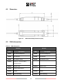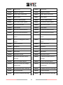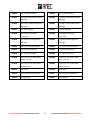
1
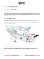
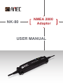
NK-80 NMEA 2000 Adaptor USER MANUAL COPYRIGHT The entire contents of this instruction manual, including any future updates, revisions, and modifications, shall remain the properties of AMEC at all times. Unauthorized copies or reproductions of this manual, either partial or whole, in any form of print and electronic media, are prohibited. The equipment mentioned in this manual can only be used in accordance with instructions contained in this manual. DISCLAIMER AMEC is devoted to publish and maintain this document. As we continue to improve our products and manuals, information presented in this document is subject to change without notice. AMEC does not make any representations or warranties (implied or otherwise) regarding the accuracy and completeness of this document and shall in no event be liable for any loss of profit or any commercial damages, including but not limited to special, incidental, consequential, or other damages. Contact us at: (Your Local Dealer/Agent Warranty Stamp) Technical Support: Sales & Marketing: Version 1.10 ALLTEK MARINE ELECTRONICS CO., LTD 5F, No. 37, Ji-Hu Road, Neihu District, Taipei, 11492, Taiwan TEL: +886 2 2627 1599 FAX: +886 2 2627 1600 www.alltekmarine.com 3 WARNING! The equipment said in this manual must only be used to which it was designed. Improper operation or installation may cause damage to the equipment. AMEC will not incur any liability as a result of equipment damage or data loss due to improper usage or installation of the equipment. It is strongly recommended reading this manual and the following safety instructions before proceeding to the installation or operation. WARNING! ELECTRICAL SHOCK HAZARD. Do not disassemble the equipment. Only qualified personnel should service the product. WARNING! PLEASE KEEP AWAY FROM DIRECT WATER CONTACT. Even though the equipment is waterproof, it is recommended to keep water away from reach. Water leaking into the equipment may cause electrical shock or fire. TURN OFF THE POWER IMMEDIATELY IF WATER LEAKS IN OR OBJECT DROPS ONTO THE EQUIPMENT. AVOID OPERATING THE EQUIPMENT WITH WET HANDS. Continue operating the equipment could hands. Despite the fact that it is safe, but like any other electric appliances, operate with dry cause electrical shock or fire. Contact your nearest distributor for service. FOREWORD AMEC thanks you for the purchase of your new NK-80 NMEA2000 adaptor. NK-80 is a clever little device that enables the communication between NMEA2000 and NMEA0183. With proper use, installation, and maintenance, the equipment will serve loyally and reliably at its optimum. For sales, services, and technical supports, please contact your local AMEC representatives or Alltek Marine Electronics Corp at [email protected] or [email protected]. You are always welcome to visit our website at www.alltekmarine.com for new product status and company update. Thank you once again. 4 Table of Contents Page 1 NK-80 INTRODUCTION ..............................................................6 1.1 What is NMEA2000? ....................................................................................... 6 1.2 NK-80 Overview .............................................................................................. 6 2 INSTALLATION ...........................................................................8 2.1 Items in the Package ....................................................................................... 8 2.2 Connection ..................................................................................................... 9 2.3 2.2.1 NMEA2000 Connections ............................................................................ 9 2.2.2 NMEA0183 Connections .......................................................................... 10 LED Indication............................................................................................... 11 3 Configuring NK-80 ................................................................... 13 3.1 Connect NK-80 to your PC ............................................................................. 13 3.2 Product Properties ........................................................................................ 14 3.2.1 NMEA 1083 baud rate setting .................................................................. 14 3.2.2 Flow Rate Setting ..................................................................................... 15 3.2.3 Device Instance ID .................................................................................... 15 3.3 Filter NMEA0183 / NMEA2000 Output Messages .......................................... 15 3.4 Save NMEA0183 Output Message Log ........................................................... 17 4 SPECIFICATIONS ...................................................................... 18 4.1 Product Specifications................................................................................... 18 4.2 Dimension .................................................................................................... 19 4.3 PGN Information........................................................................................... 19 4.4 NMEA0183 Information ................................................................................ 22 5 FCC INTERFERENCE STATEMENT ............................................... 23 6 DECLARATION OF CONFORMITY .............................................. 23 5 1 NK-80 INTRODUCTION 1.1 What is NMEA2000? The NMEA2000 transmits data through Controller Area Network (Can Bus). It simplifies the connections and enables information sharing among different devices through a single trunk cable. Compared with NMEA0183 in “RS422” interface, NMEA2000 has better transmission reliability and shares data easier in a network. 1.2 NK-80 Overview NK-80 NMEA2000 adaptor (as known as NK-80) is a gateway between NMEA0183 electronic devices and NMEA2000 device/network. NK-80 allows users to connect their existing NMEA 1083 devices to an NMEA2000 network. The key features of NK-80 are shown as follows: 1) Extend NMEA0183 Devices into NMEA2000 Network NK-80 is a gateway between NMEA0183 electronics devices and NMEA2000 device/network. NK-80 allows users to connect NMEA2000 network with their existing NMEA0183 devices. 6 2) Conversion between NMEA2000 and NMEA0183 3) Support Latest NMEA2000 Sentences NK-80 supports wide range of NMEA2000 sentences with latest NMEA association released documents. 4) User-friendly Configuration Utility NK-80 also provides a configuration tool which allow user to modify NK-80 baud rate and manage/filter NMEA2000/NMEA0183 sentences easily. 5) NMEA2000 Certified, ensures product quality is reliable in most extreme conditions. 6) Fully galvanically isolated for electrical spike protection. Isolated power is provided through NMEA2000 network, NK-80 requires no additional battery source. 7 2 INSTALLATION 2.1 Items in the Package The NK-80 standard package is listed in Table 1. It is also illustrated in Figure 1. Table 1 Standard Equipment List No. Description Qty 1 AMEC NK-80 NMEA2000 adaptor 1 2 Manual 1 3 Screw M4 4 4 CD 1 1. NK-80 x1 2. Manual x1 Figure 1 3. Screw M4 x4 Standard Package 8 4. CD x1 2.2 Connection Diagram below shows the physical attributes of NK-80. NMEA 2000 Micro -C male NMEA 0183 LED 1 LED 2 0.1 meter 2.2.1 1 meter NMEA2000 Connections The Micro-C male connector is an NMEA2000 standard connector. Connect this connector to any available Micro-C female connector in the NMEA2000 network. NET-S Shield 2 NET-C 3 3 3 Figure 2 1 5 3 3 4 NET-H 3 NET-L Pin Definitions of the Micro-C Male Connector 9 2.2.2 NMEA0183 Connections The NMEA0183 cable provides flexible wiring to devices. Please follow the NMEA0183 cable description below when wiring to an NMEA0183 device. Table 2 Wire Information for NMEA0183 Cable Pin Wire color Name 1 RED TXP Positive(+); NMEA0183 Data output 2 GREEN TXN Negative (-); NMEA0183 Data output 3 BLACK RXP Positive(+); NMEA0183 Data input 4 BLUE RXN Negative (-); NMEA0183 Data input 5 SHIELD GND Ground Function Wiring NMEA0183 to NMEA0183/RS-422 Device Please follow the wiring diagram below to connect an NMEA0183/RS-422 device. NK-80 NMEA0183 External NMEA0183/RS-422 device TXP (Red) RXP TXN (Green) RXN RXP (Black) TXP RXN (Blue) TXN Figure 3 NMEA0183 to RS-422 Connection NOTE: Please ensure the connecting device is fully NMEA0183 compliant. 10 Wiring NMEA0183 to RS-232/PC Please follow the wiring diagram below to connect to RS-232/PC NK-80 NMEA0183 External RS-232/PC TXP (Red) RX TXN (Green) GND RXP (Black) TX RXN (Blue) GND Figure 4 NMEA0183 to RS-232 Connection NOTE: Please ensure the wire definitions of RS-232/PC are correct during wiring. 2.3 LED Indication NK-80 has two LED indicators: LED 1 and LED 2. LED 1 flashes blue light when processing/receiving NMEA2000 messages. LED 2 flashes green light when processing/receiving NMEA0183 messages. Figure 5 LED Indication of NK-80 The details on indicators statuses are shown in the following table. 11 Table 3 Description of Indicator Statuses Indication Status Description LED 1 ●(Blue) Flash Receiving NMEA2000 messages LED 2 ●(Green) Flash Receiving NMEA0183 messages LED 1 ●(Blue) Flash simultaneously in a LED 2 ●(Green) 5 seconds interval LED 1 ●(Blue) LED 2 ●(Green) Steady Normal Operation During Firmware Upgrading LED 1 ●(Blue) Flash takes more than 5 LED 2 ●(Green) seconds System/Power Failure* *NOTE: If it takes more than 5 seconds to see LED activities, please verify your NMEA2000 network power output voltage. 12 3 Configuring NK-80 With the help of AMEC NK-80 Configuration Utility, NK-80 can be configured with other NMEA0183 baud rates, flow rates and NMEA 2000 device instance. The software delivers also comprehensive product information about your NMEA adaptor which is helpful for error diagnosis. For advanced applications, users can also filter NMEA0183 / NMEA2000 output messages and display the incoming NMEA 2000 sentences. 3.1 Connect NK-80 to your PC Step 1: Connect NK-80 adaptor to PC through RS-232/USB and ensure power is available from the NMEA2000 network. *NOTE: PC connection is required for advanced configuration. Step 2: Run AMEC NK-80 Configuration utility. In the window “Serial Port and Baud Rate Setting”, there are 2 options to connect the software with your NMEA adaptor: Auto: The system will scan all connected ports and their available baud rates and establish connection automatically. Manual: Configure baud rate and port manually. The default baud rate is 4800. Manually enter port value and NMEA0183 baud rate. If the baud rate is unknown, choose Auto. Then, click Connect to connect NK-80. Click on “Connect”, to connect AMEC NMEA Configuration utility with NK-80. Figure 6 AMEC NMEA Configuration Utility 13 3.2 Product Properties 3.2.1 NMEA 1083 baud rate setting The tab PROPERTIES delivers complete information about the adaptor, which should enable a better communication when technical support is needed: NMEA 0183 baud rate: default baud rate is 4800 and can be changed with the pull-down menu below with 4800, 9600, 38400 as options. After new baud rate is set, press “Apply” to confirm the choice and the device will be disconnected automatically. To reestablish the connection, choose the new baud rate and repeat the steps described in 3.1. Figure 7 Properties Tab 14 3.2.2 Flow Rate Setting The flow rate setting enables the users to configure how frequently received messages will be transmitted. When flow rate is set to 0, received messages will be transmitted immediately. When it´s set to 1 second, then received messages will be collected and transmitted every 1 second and so on and so forth. Lowest frequency available is 5 second. 3.2.3 Device Instance ID The adaptor comes with the device instance value set to 0 as default. If the adaptor is connected to multiple of same devices on a NMEA 2000 network, you may find it necessary to set the device instances of other devices of this type so that they are different. The further options enable you to change the upper device instance or lower device instance fields of the adaptor, provided that it supports modification of these fields over the network. 3.3 Filter NMEA0183 / NMEA2000 Output Messages Step 1: At the CONFIGURATION tab, expand the message list on the left and click on a desired message to configure. Figure 8 NMEA Message Filtering HINT: Double click to expand the message groups will show their message names. 15 Step 2: Once clicked on the desired message, the message properties will reveal on the right panel. On the panel choose the needed attributes and click on Apply. Figure 9 NMEA Message Filtering Note: All message settings are enabled in factory default. The Default button restores all message settings back to factory default. 16 3.4 Save NMEA0183 Output Message Log Click on the NMEA0183 DATA VIEW (OUTPUT) tab to view message log history. To record a log session, click on the disk button to start recording. The system will prompt you first to save the log. It continues logging till the icon is click again. Figure 10 NMEA0183 Data Log NOTE: NK-80 configuration utility can only log NMEA0183 output sentences processed from NMEA2000 messages. Shown below is the content of a log file. Figure 11 A Sample Log File 17 4 SPECIFICATIONS 4.1 Product Specifications APPLICABLE STANDARDS NMEA2000 standard version1.2 (2004) CERTIFICATIONS NMEA2000 ® Parameter Recessive bus voltage NMEA2000 CAN Bus line Transmitter Conditions VTXD = VDD; no load Min. 2.0V Max. 3.0V Dominant bus voltage NET-H VTXD = 0.8V 2.75V 4.5V Dominant bus voltage NET-L Recessive differential output voltage VTXD = 0.8V 0.5V 2.25V VTXD = 2V; no load -500mV 50mV 1.5V 3.0V Dominant differential output voltage 40Ω < RL < 60Ω NMEA2000 CAN Bus line Receiver NET-H, NET-L common-mode input resistance typical 100 KΩ Differential input resistance Configurable baud rate Operation temperature typical 100 KΩ NMEA0183 Baud Rate Settings 4800, 9600, 38400 bps (default is 38400 bps) Environmental -20°C~+55°C Storage temperature -25°C~+70°C Water proof IP54 Humidity Length 0~80% RH PHYSICAL 132 mm Width 30 mm Height 22.8 mm Cable Lengths NMEA2000 cable: 0.1m NMEA0183 cable: 1 m Weight < 150 g ELECTRICAL NMEA2000 LEN (Load Equivalency Number) 1 (under 50 mA) POWER SUPPLY Supply Voltage from CAN Bu 12VDC / 24VDC (Typical) 18 4.2 Dimension Figure 12 NK-80 Main Body Dimension (mm) 4.3 PGN Information Table 4 PGN Information Transmit PGN Receive Description PGN Description 59392 ISO Acknowledgment 59392 ISO Acknowledgment 59904 ISO Request 59904 ISO Request 60928 ISO Address Claim 60928 ISO Address Claim 126464 PGN List - Transmit PGN's 126992 System Time group function 126992 System Time 126996 Product Information 127245 Rudder 127245 Rudder 127250 Vessel Heading 127250 Vessel Heading 19 127251 Rate of Turn 127251 Rate of Turn 127258 Magnetic Variation 127258 Magnetic Variation 128259 Speed, Water referenced 128259 Speed, Water referenced 128267 Water Depth 128267 Water Depth 129025 Position, Rapid Update 129025 Position, Rapid Update 129026 COG & SOG, Rapid Update 129026 COG & SOG, Rapid Update 129029 GNSS Position Data 129029 GNSS Position Data 129033 Time & Date 129033 Time & Date 129038 AIS Class A Position Report 129038 AIS Class A Position Report 129039 AIS Class B Position Report 129039 AIS Class B Position Report 129040 AIS Class B Extended Position 129040 AIS Class B Extended Position Report 129041 Report AIS Aids to Navigation (AtoN) 129041 Report AIS Aids to Navigation (AtoN) Report 129283 Cross Track Error 129283 Cross Track Error 129284 Navigation 129284 Navigation 129291 Set & Drift, Rapid Update 129291 Set & Drift, Rapid Update 129539 GNSS DOPs 129539 GNSS DOPs 129540 GNSS Sats in View 129540 GNSS Sats in View 129792 AIS DGNSS Broadcast Binary 129792 AIS DGNSS Broadcast Binary Message Message 129793 AIS UTC and Date Report 129793 AIS UTC and Date Report 129794 AIS Class A Static and Voyage 129794 AIS Class A Static and Voyage Related Data Related Data 129795 AIS Addressed Binary Message 129795 AIS Addressed Binary Message 129796 AIS Acknowledge 129796 AIS Acknowledge 129797 AIS Binary Broadcast Message 129797 AIS Binary Broadcast Message 20 129800 AIS UTC/Date Inquiry 129800 AIS UTC/Date Inquiry 129801 AIS Addressed Safety Related 129801 AIS Addressed Safety Related Message 129802 Message AIS Safety Related Broadcast 129802 Message AIS Safety Related Broadcast Message 129803 AIS Interrogation 129803 AIS Interrogation 129804 AIS Assignment Mode 129804 AIS Assignment Mode Command 129805 Command AIS Data Link Management 129805 Message AIS Data Link Management Message 129806 AIS Class A Position Report 129806 AIS Class A Position Report 129807 AIS Group Assignment 129807 AIS Group Assignment 129808 DSC Call Information 129808 DSC Call Information 129809 AIS Class B “CS” Static Data 129809 AIS Class B “CS” Static Data Report, Part A 129810 Report, Part A AIS Class B “CS” Static Data 129810 Report, Part B AIS Class B “CS” Static Data Report, Part B 130306 Wind Data 130306 Wind Data 130311 Environmental Parameters 130311 Environmental Parameters 130312 Temperature 130312 Temperature 21 4.4 NMEA0183 Information Table 5 NMEA0183 Information Formatter mnemonic code Name RMC Recommended minimum specific GNSS data GSA GNSS DOP and active satellites GGA Global positioning system (GPS) fix data GSV GNSS satellites in view GLL Geographic position–latitude/longitude VTG Course over ground and ground speed ZDA Time and date VDM AIS VHF data-link message VDO AIS VHF data-link own-vessel report DSC Digital selective calling information RSA Rudder sensor angle VHW Water speed and heading VLW Dual ground/water distance DPT Depth DBT Depth below transducer XTE Cross-track error, measured APB Heading/track controller (autopilot) sentence B ROT Rate of turn VWR Relative Wind Speed and Angle MWV Wind speed and angle MWD Wind direction and speed MTW Water temperature VDR Set and drift BWC Bearing and distance to waypoint – great circle BWR Bearing and distance to waypoint – rhumb line 22 5 FCC INTERFERENCE STATEMENT This equipment has been tested and found to comply with the limits for a Class A digital device, pursuant to Part 15 of FCC Rules. These limits are designed to provide reasonable protection against harmful interference in a residential installation. This equipment generates uses and can radiate radio frequency energy and, if not installed and used in accordance with the instructions, may cause harmful interference to radio communications. However, there is no guarantee that interference will not occur in a particular installation. If this equipment does cause harmful interference to radio or television reception, which can be determined by turning the equipment off and on, the user is encouraged to try to correct the interference by one of the following measures: Reorient or relocate the receiving antenna. Increase the separation between the equipment and receiver. Connect the equipment into an outlet on a circuit different from that to which the receiver is connected. Consult the dealer or an experienced radio/TV technician for help. This device complies with Part 15 of the FCC Rules. Operation is subject to the following two conditions: 1) This device may not cause harmful interference, and 2) This device must accept any interference received, including interference that may cause undesired operation. 6 DECLARATION OF CONFORMITY Hereby, Alltek Marine Electronics Corp. (AMEC) declares that this NK-80 is in compliance with the essential requirements and other relevant provisions of Directive 1999/5/EC. 23