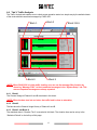
1
1 COPYRIGHT The entire contents of this instruction manual, including any future updates, revisions, and modifications, shall remain the property of AMEC at all times. Unauthorized copies or reproduction of this manual, either in part or whole, in any form of print and electronic media, is prohibited. The contents herein can only be used for the intended purpose of this manual. DISCLAIMER AMEC is devoted to publish and maintain this product manual. As we continue to improve our AIS products to satisfy all customers’ needs, information in this document is subject to change without notice. AMEC does not make any representations or warranties (implied or otherwise) regarding the accuracy and completeness of this document and shall in no event be liable for any loss of profit or any commercial damage, including but not limited to special, incidental, consequential, or other damage. Contact us at: Technical Support: (Your Local Dealer/Agent Warranty Stamp) Sales & Marketing: ALLTEK MARINE ELECTRONICS CO., LTD Version 1.02 5F, No. 37, Ji-Hu Road, Neihu District, Taipei, 11492, Taiwan TEL: +886 2 2627 1599 FAX: +886 2 2627 1600 www.alltekmarine.com I WARNING! FOR USERS IN THE UNITED STATES OF AMERICA ONLY WARNING: It is a violation of the rules of the Federal Communications Commission to input an MMSI that has not been properly assigned to the end user, or to otherwise input any inaccurate data in this device. ★ The entry of static data into this device shall be performed by the vendor of the device or by an appropriately qualified person in the business of installing marine communications equipment on board vessels. ★ Instructions on how to accurately enter and confirm static data in the device can be found in Section 4 of this user manual. The equipment said in this manual must only be used to which it was designed. Improper operation or installation may cause damage to the equipment or injury to personnel. AMEC will not incur any liability of equipment damage or personal injury due to improper use or installation of the equipment. It is strongly recommended to read this manual and the following safety instructions before proceeding to installation or operation. SAFETY INSTRUCTIONS WARNING WARNING ELECTRICAL SHOCK HAZARD. TURN OFF THE POWER IMMEDIATELY IF THE EQUIPMENT IS EMMITTING SMOKE OR FIRE. Do not open the case of the equipment Only qualified personnel could work on the interior of the equipment. Continue operating the equipment could cause electrical shock or fire. Contact your nearest distributor for service. TURN OFF THE POWER IMMEDIATELY IF WATER LEAKS INTO THE EQUIPMENT OR OBJECT DROPS INTO THE EQUIPMENT. EVENTHOUGH THE EQUIPMENT IS WATERPROOF, PLEASE AVOID DIRECT CONTACT WITH RAIN OR SPLASHING WATER. Continue operating the equipment could cause electrical shock or fire. Contact your nearest distributor for service. Electrical shock or fire could be resulted if water leaks into the equipment. DO NOT DISASSEMBLE OR MODIFY THE EQUIPMENT. DO NOT PLACE ANY LIQUID-FILLED CONTAINER ON TOP OF THE EQUIPMENT. Improper disassemble or modification could cause electrical shocks, fire, or personal injury. Electrical shocks could be resulted if the device is contaminated with liquid. AVOID OPERATING THE EQUIPMENT WITH WET HANDS. Electrical shocks could be resulted if operating with wet hands. II Table of Contents 1 2 I. COPYRIGHT & DISCLAIMER II. WARNING & SAFETY INSTRUCTION INTRODUCTION ........................................................................................................................ 1 1.1 PASO-350 Overview ................................................................................................................. 1 1.2 PASO-350 Features .................................................................................................................. 1 1.3 About This Manual ................................................................................................................... 1 INSTALLATION.......................................................................................................................... 2 2.1 General ..................................................................................................................................... 2 2.2 Installation Requirement Overview ......................................................................................... 2 2.2.1 2.3 Installation Material ...................................................................................................... 2 2.2.1.1 Items in the Package ............................................................................................... 2 2.2.1.2 Recommended Tools............................................................................................... 3 Installation Procedures ........................................................................................................... 4 2.3.1 Step by Step Installation Instructions ......................................................................... 4 2.3.2 Connector Pin Definition and Wiring .......................................................................... 4 2.3.2.1 LCT (local Craft Terminal) Connector ...................................................................... 4 2.3.2.2 NMEA 0183 Connector ............................................................................................ 4 2.3.2.3 ALARM Connector................................................................................................... 4 2.3.3 Ground Terminal and Connection ............................................................................... 5 2.4 VHF Antenna Installation ......................................................................................................... 5 2.5 GPS Antenna Installation ........................................................................................................ 5 2.6 Antenna Cabling ...................................................................................................................... 5 2.7 Lightning Protection ................................................................................................................ 6 2.8 PASO-350 External Connections ............................................................................................ 6 2.9 AMEC AIS Repeater Manager Software Installation .............................................................. 7 III 3 4 GET STARTED......................................................................................................................... 11 3.1 Turing Power On / Off ............................................................................................................ 11 3.2 Front Panel Indicators ........................................................................................................... 11 AMEC AIS Repeater Manager ................................................................................................ 13 4.1 General ................................................................................................................................... 13 4.2 Tab 1: System Indication ....................................................................................................... 14 4.3 4.4 4.5 4.6 4.2.1 Block 1: ED Indicator & Testing Button .................................................................... 15 4.2.2 Block 2: Marquee Message ........................................................................................ 15 4.2.3 Block 3: System Time ................................................................................................ 16 Tab 2: GPS Information ......................................................................................................... 16 4.3.1 Block 1: LED Indicator & Testing Button .................................................................. 16 4.3.2 Block 2: Marquee Message ........................................................................................ 16 4.3.3 Block 3: Satellite Signal Strength .............................................................................. 16 Tab 3: Traffic Analysis ........................................................................................................... 17 4.4.1 Block 1 ........................................................................................................................ 17 4.4.2 Block 2 ........................................................................................................................ 17 4.4.3 Block 3 and Block 6.................................................................................................... 17 4.4.4 Block 4 ........................................................................................................................ 18 4.4.5 Block 5 ........................................................................................................................ 18 Tab 4: System Status ............................................................................................................. 18 4.5.1 General ........................................................................................................................ 18 4.5.2 Processor Kernel ........................................................................................................ 18 4.5.3 Interface ...................................................................................................................... 18 4.5.4 Device ID ..................................................................................................................... 19 4.5.5 GPS Functionality....................................................................................................... 19 4.5.6 System Status Tester ................................................................................................. 19 Tab 5: System Setup .............................................................................................................. 19 4.6.1 General Settings ......................................................................................................... 19 4.6.2 Transceiver Setting .................................................................................................... 20 IV 5 4.6.3 Message Filter ............................................................................................................ 21 4.6.4 About ........................................................................................................................... 22 Appendix ................................................................................................................................. 23 5.1 Product Specification ............................................................................................................ 23 5.2 Dimensions ............................................................................................................................ 25 5.3 Accessories (Optional) .......................................................................................................... 26 6 AMEC WORLDWIDE WARRANTY .......................................................................................... 27 7 DECLARATION OF CONFORMITY ......................................................................................... 28 8 ABBREVIATIONS .................................................................................................................... 29 V 1 INTRODUCTION 1.1 PASO-350 Overview AMEC PASO-350 is a Simplex AIS Repeater. It complies with all the requirements and regulations imposed by the international standard. As a repeater, PASO-350 extends AIS coverage and attempts to overcome terrain obstacles that block AIS radio propagation. Within the AIS service network, PASO-350 is on the same layer as AIS base stations. There is direct access to the VHF/RF domain equipments for reception and transmission of AIS VDL messages. The PASO-350 AIS Repeater doubles the VDL link load for AIS mobile stations and should only be used in areas with relatively low AIS traffic density. If the installation site’s AIS traffic loading is very high, some VDL message dropping could occur due to AIS repeater standards. It is recommended that the installation sites for PASO-350 have less than 25% of the VDL link load. 1.2 PASO-350 Features Provides a gap-filler at remote and isolated locations During retransmission different timeslot is used, however messages are sent out on the same channel where they were received. Comply with international standards ensuring AIS system integrity Synchronize on any AIS station that has direct UTC Modularized structure Clear indications for GPS and device status Additional features for LED test, ACO (Alarm Cut Off) and LCT (Local Craft Terminal) for easy maintenance operations Relay contact for external alarm 1.3 About This Manual The manual contains installation instructions and operating information for PASO-350. While most of the installation can be performed by user, a final commissioning can be done by your local agent/dealer where needed or required. AMEC and the local agent/dealer will not bear any responsibilities over any damages resulted in improper installation by unauthorized agent/dealer. 1 2 INSTALLATION 2.1 General This section describes on-site PASO-350 installation and cable connections. PC or laptop is required for configuration and future maintenance if necessary. 2.2 Installation Requirement Overview Ensure that deployment site is well suited: Ensure the environment is suitable for the installation and operation. Site has lightning rod installed with proper grounding to avoid lightning strikes. Site has a basic ventilated environment. If necessary install cable ladders at the site when needed. Standard 19-inch rack is installed for the repeater. Site electrical installation is well completed and inspected. Power source is installed and tested for +24V DC and/or 100~240 VAC. The rack and the repeater are both grounded to minimize risks of lighting damages or accidents. VHF and GPS Antenna systems are installed and tested. Both cables are equipped with gas-tube or arrestor to avoid lightning strikes. Cabling and sensors for external alarms are installed. 2.2.1 Installation Material This section contains lists of hardware, tools and requirements for installation. 2.2.1.1 Items in the Package PASO-350 package comes with the following items. If any item is missing, notify AMEC or your local dealer immediately. PASO-350 main unit Power cable for 100~240V AC (1.8m) One LCT Cable (1.2m) CD-ROM with AMEC AIS Repeater Manager and the digital copy of this user manual Frame grounding cable (1.5m; AWG#12) M5 screws x 4 2 2.2.1.2 Recommended Tools The following tools may be required for the installation. Tool Description Screwdriver Knife Plate shears Cable cutter Multi-meter 3 2.3 Installation Procedures 2.3.1 Step by Step Installation Instructions Please follow the steps below to install PASO-350. 1. Ensure the standard 19-inch rack is firmly fixed. 2. Position PASO-350 on the rack and aligning the holes on the brackets with the holes on the rack, and then use the screws to mount PASO-350. 3. Connect 100 ~ 240V AC or +24V DC cable from battery bank to PASO-350’s power terminals. 4. Ensure the power terminals for 100 ~ 240V AC and/or +24V DC are proper fixed. 5. Connect LCT cable (from PASO-350 front panel) to laptop or PC to configure PASO-350. 2.3.2 Connector Pin Definition and Wiring The wiring details of the LCT/ NMEA 0183/ ALARM connectors are listed below. 2.3.2.1 LCT (local Craft Terminal) Connector Pin Name Function 2 Rx LCT data receiver 3 Tx LCT data transmitter 5 GND Ground 2.3.2.2 NMEA 0183 Connector Pin Name Function 1 RXP Positive(+); NMEA0183 Data input 2 RXN Negative (-); NMEA0183 Data input 3 TXP Positive(+); NMEA0183 Data output 4 TXN Negative (-); NMEA0183 Data output 2.3.2.3 ALARM Connector Pin Name Function 1 ALM A Alarm contact A 2 ALM B Alarm contact B 4 2.3.3 Ground Terminal and Connection User the provided 1.4m ground cable and connect the end of lug to the ground terminal on PASO-350 and other end to one of the protection grounds at rack. If the ground cable is too long, please cut it to a proper length. 2.4 VHF Antenna Installation The quality and positioning of the antenna is the most important factor dictating AIS performance. It is recommended that a VHF antenna with omni directional vertical polarization be specifically tuned for AIS operation band. Since the range of VHF signals is largely decided by line of sight distance, AIS antenna should be placed as high as possible and at least 5 meters away from any constructions made of conductive materials. To avoid interference, the VHF antenna location should be placed in accordance to the figure below. Ensure a free 360˚ horizon with a vertical observation of 5˚. 5˚ High power transmitting antenna Ensure the GPS antenna is not within the transmitting beam of other high power transmitting antenna. VHF Antenna The recommended . vertical distance between antennas is 2m. Other VHF Antenna 3m The recommended horizontal distance between GPS antennas and other antennas is 3m. 10m The recommended horizontal distance between antennas is 10m. Other transmitting antenna We recommend you choose AMEC AIS VHF antenna. To save space, you can also choose VHF/GPS combo antenna provided by AMEC. 2.5 GPS Antenna Installation The GPS antenna must be installed where it has a clear view of the sky, so that it accesses the horizon freely through 360°, with a vertical observation of 5 to 90 degrees above the horizon. We recommend you choose AMEC AIS GPS antenna. To save space, you can also choose VHF/GPS combo antenna provided by AMEC. 2.6 Antenna Cabling When connecting the PASO-350 with cables(s), take note of the following precautions. Do not bend the cables (s). Each coaxial cable should be setup separately and can only be setup in a single cable tube. Each coaxial cable should keep a 10m safe distance with the power cable. Connecting port of the coaxial cable should be insulated. 5 2.7 Lightning Protection For both VHF and GPS, lightning arrestors are required for both antenna cables. There are a lot of coaxial arrestors available from various suppliers. It is required to specify applied frequency and the maximum output when choosing lighting arrestors. 2.8 PASO-350 External Connections Fuse (10A) ECS Local Craft Terminal VHF Antenna (Connector -M Jack) GND 100-240V AC 24V DC ALARM GND Cable GPS Antenna 6 2.9 AMEC AIS Repeater Manager Software Installation The AMEC AIS Repeater Manager provides users with AIS information on computer; users may browse the relative positions of surrounding vessels and the dynamic and static information regulated by IMO. For professional users or further details, we suggest connecting AMEC PASO-350 with other marine electronic products such as ECS or Radar to achieve better performances. Please find the AMEC AIS Repeater Manager in the CD-ROM we provided; and follow the steps below to install the program. Please find the AMEC AIS Repeater Manager in the CD-ROM we provided; and follow the steps below to install the program. Step 1: Put the CD-ROM into your computer, and double click on Step 2: A welcome window will pop up. Please click to continue. 7 . Step 3: Please read and accept the license agreement before clicking on Step 4: Please fill in the required user information and click on 8 to continue. to continue. Step 5: Please choose a folder to install the application; and then click on Step 6: Please click on to continue the installation. 9 to continue. Step 7: The AMEC AIS Repeater Manager starts to install, please wait for it to finish. Step 8: When the installation is completed, please click on setting. And run the AMEC AIS Repeater Manager program. 10 to complete the 3 GET STARTED 3.1 Turing Power On / Off TURNING POWER ON: Step 1: Check the input voltage. PASO-350 input voltage is 100 ~ 240V AC or 24V DC. Step 2: Connect the PASO-350 with power input(s). Step 3: Press the circuit-break at rear panel to “ON”. Then switch the power at front panel to “ON”. Step 4: The green power status indicator (DC IN /AC IN) will turn to solid from flashing. Step 5: When the power status indicator turns solid green, the unit functions normally and automatically. The “Rx” channel indicator flashes once when receiving AIS message and the “Tx” channel indicator flashes once when transmitting AIS message. TURNING POWER OFF: Step 1: Switch the power to “OFF”. Step 2: The unit shuts down and the power status indicator turns off. *NOTE1: PASO-350 uses 10A fuses. If a fuse was ever blown, unscrew the fuse cover at the rear side of the repeater and replace the bad fuse. 3.2 Front Panel Indicators Please see the table from below for the indicators description. 11 LED Indicators Indications Status Shape DC IN Rectangle Description Color Green DC will turn active when the 24 DC voltage is higher than the output voltage of AC adapter (built in PASO-350) POWER TESTING AC IN Rectangle Green AC will turn active when the voltage from AC adapter (built in PASO-350) is large or equal to 24 DC voltage Power Switch Rectangle Orange Main power switch for PASO-350 BIIT (Built-In Integration Test) Rectangle Red LED will turn on when BIIT fails UTCSync Rectangle Blue LED will turn on when GPS fix ACO (Alarm Cut Off) Round Red LED will turn on when ACO (switch) activates ACO (switch) LED Test Switch to cut off alarm signal Round Green All the LEDs at front panel will turn on LED Test (switch) CHANNEL LED will turn on when LED Test (switch) activates CHA_TX Yellow LED will flash when Channel A transmits AIS signal CHA_RX Green LED will flash when Channel A receives AIS signal CHB_TX Yellow LED will flash when Channel B transmits AIS signal CHB_RX Green LED will flash when Channel B receives AIS signal Rectangle 12 4 AMEC AIS Repeater Manager 4.1 General AMEC AIS Repeater Manager enables user to view system status and allows configuring PASO-350. When you start AMEC AIS Repeater Manager, the Device Wizard window pops up and prompt for connection setting. User can choose Auto or Manual Mode to connect AMEC AIS Repeater Manager and the device. *NOTE1: The PASO-350 can be connected later on by clicking the quick connect button lower left corner on the main view. at the *NOTE2: If the system is disconnected, functions in AMEC Repeater Manager are disabled. When the Connect button is clicked, the “Config AIS Serial Port” window pops up and enables user to reset the connection of the device. When the serial port cannot be identified in Auto Mode, click the Device Wizard to set a proper system connection. After entering the AMEC AIS Repeater Manager, user can access the five system tabs: System Indication, GPS Information, Traffic Analysis, System Status, and System Setup. 13 System Indication: User can check the operation status of the repeater. A marquee message will also notify system status and channel loading messages. GPS Information: GPS satellite messages will be shown in this tab. Traffic Analysis: Data including channel loading and repeater performance will be shown in this tab. User can also check the operating status of the channels in the dynamic slot map. System Status: system status and operating status are listed in this tab. System Setup: Functions for logging, message filtering and disabling the repeater can be found in this tab. 4.2 Tab 1: System Indication The System Indication Panel is divided to 3 blocks: LED Indicator, Testing Button, Marquee Message, and System Time. Block 2 Block 1 14 Block 3 4.2.1 Block 1: ED Indicator & Testing Button After AMEC AIS Repeater Manager is successfully connected to the device, the LED Indicator and Testing Button will synchronize with the front panel. For the description of LED indicators please refer to Table 3-2 Front Panel Indicators Description. 4.2.2 Block 2: Marquee Message The Marquee Message block shows the message listed below. No 1 2 Name Traffic Loading Repeater Performance Status Descriptions Low Channel Loading < 30% Normal 30 % < Channel Loading < 50% High Channel Loading > 50% Perfect: Channel Loading = 100% Good 90% < Repeater Performance < 99% Acceptable 80% < Repeater Performance < 89% Downgrade 10% < Repeater Performance < 79% Defective Repeater Performance < 10% Lost 3 GPS Status 2D 3D 12.5W 5W 4 Transmit Power 2W Unknown 5 Repeater Function 6 Processor Kernel 7 Interface On Off OK Fail OK Fail 15 System might have fault or malfunction 4.2.3 Block 3: System Time User can check the time set on the Laptop or PC in this block. 4.3 Tab 2: GPS Information User can check the GPS status of PASO-350 in the Global Positioning System tab. Block 1 Block 2 Block 3 4.3.1 Block 1: LED Indicator & Testing Button The received satellite locations will be shown on the earth globe figure. When the satellite messages are in use, the circle icons will turn to lime color. Otherwise, they stay blue. 4.3.2 Block 2: Marquee Message The columns show the UTC time and the location of PASO-350 from GPS. 4.3.3 Block 3: Satellite Signal Strength The columns show the strength and numbers of satellites signals. When the satellite messages are in use, the bars of Satellite Signal Strength will turn to lime color. Otherwise, stay blue. 16 4.4 Tab 3: Traffic Analysis The Traffic Analysis tab enables user to check recent operation status in a simple way by the statistical data of the received and transmitted messages by PASO-350. Block 1 Block 4 Block 2 Block 3 & 6 Block 5 *NOTE: When PASO-350 is in high traffic loading, user can use the message filter function by choosing “Message Filter” to block unwanted messages in the “System Setup” tab. This ensures important messages are always repeated. 4.4.1 Block 1 The Channel Usage of Channel A and B are shown in this block. *NOTE: When the bars turn into red color, the traffic load is close to saturation. 4.4.2 Block 2 The bars show the Channel Usage History of Channel A and B. 4.4.3 Block 3 and Block 6 The statistical data in “Duration Time” is recorded in this block. The duration time can be set up in the “Statistical Period” on the left top of this page. 17 4.4.4 Block 4 The two bars present the amount of Rx and Tx messages in Channel A and Channel B. Lime color represents received message numbers, and orange color represents transmitted message numbers. 4.4.5 Block 5 The Repeater Performance History on Channel A and B are shown in this block. 4.5 Tab 4: System Status 4.5.1 General User can check the monitoring information including “System Power”, “Background Noise”, “Transmit Power”, and “GPS Status”. System Power: DC or AC in use Background Noise: Channel background noise detecting value Transmit Power: 12.5W, 5W, 2W GPS Status: Lost, 2D, 3D 4.5.2 Processor Kernel User can check the kernel status including “CPU”, “RAM”, “ROM”, “CACHE”, and “DATAFLASH”. 4.5.3 Interface User can confirm the function including “LCT” and “NMEA-0183”. 18 4.5.4 Device ID User can see the PASO-350 information including “System Model”, “Serial No”, “Manufacturer No”, and “Firmware Version”. 4.5.5 GPS Functionality User can check the received GPS sentences including “GGA”, “GSV”, “RMA”, and “RMC”. 4.5.6 System Status Tester After the “Start Test” button is pressed, the system will collect the PASO-350 system information during the run time. 4.6 Tab 5: System Setup 4.6.1 General Settings User can select the Enable Auto Saving function to activate the log saving, and the system will record the operating status in PASO-350 in the time period which can be setup in “Record Time”. Click the button and a window will pop up allowing user to save the record with desired file name and file path. The system will automatically add the record date and time after the file name. (Ex: FileName20101010_094112.txt) 19 *NOTE: If the file path is not designated, the file will be automatically saved in the folder you installed AMEC AIS Repeater Manager. 4.6.2 Transceiver Setting Repeat Function: User can choose “ON” to enable the Repeat Function or choose “OFF” to disable the Repeat Function. Transmit Power: User can choose the desired transmit power (12.5W, 5W, 2W). 20 4.6.3 Message Filter User can choose the desired messages to be repeated in this page as filter function. 21 4.6.4 About The copyright statement will show in this page. 22 5 Appendix 5.1 Product Specification STANDARDS ITU 1371-3 24 / IALA A.126 IEC 61162-1/2 IEC 61108-1 VHF CHANNELS Frequency 161.975 MHz /162.025 MHz Frequency accuracy ± 500 Hz Channel Bandwidth 25 KHz Number of RF Channels Receivers x 2 /Transmitter x 1 Antenna Port Impedance 50 ohm TRANSMITTER Power Output 33, 37, and 41 dBm (2W, 5W, 12.5W) 50 ohm load Power Deviation ± 1.5 dB Data Rate 9600 bps Modulation Scheme GMSK/FM RECEIVER Sensitivity, 20% PER -107 dBm GNSS RECEIVER Receiving Channels 12 channels Output Rate 1 Hz POWER Main Input Power 100 ~ 240V AC, 50/60Hz Alternative Power 24V DC 23 LED 1. Two Power (Status) Indicators 2. Two Rx Channel Indicators 3. Two Tx Channel Indicators 4. One UTC Sync Indicator 5. One BIIT Indicator 6. One ACO (Alarm Cut Off) Indicator 7. One LED Test Indicator 24 5.2 Dimensions Front View Top View 25 Side View Back View 5.3 Accessories (Optional) The following accessories are available from AMEC. Contact our local dealer/agent for more details. Item Description Product Code 1 VHF Antenna TENTA-11 2 GPS Antenna AGGRESSOR-21 Remark Length: 1,200 mm Dimension: 90.5 mm(Diameter) x 108.5 mm(H) 3 VHF/GPS Combo Antenna TENTA-12 26 Length: 1,680 mm 6 AMEC WORLDWIDE WARRANTY Limited warranty Subject to the terms, conditions and limitations set forth in this Worldwide Limited Warranty (hereinafter the “Warranty”), AMEC warrants that its products, when properly installed and used, will be free from defects in material and workmanship for a period of twelve (12) months, from the date of first purchase (the ‘Warranty Period’) For the purposes of this warranty, ‘date of first purchase’ means the date that the product was purchased by the first retail customer, or by the institutional customer, or in the case of a product installed on a new vessel or any other marine related platform by a certified AMEC original equipment manufacturer (a ‘AMEC OEM’), the date that such vessel was purchased by the first retail customer. AMEC will, at its sole option, repair or replace any defective products or components returned during the Warranty Period in accordance with the terms, conditions and limitations set forth below. Such repairs or replacement will be the sole remedy of the customer under this Warranty. Standard Warranty Service To qualify for standard warranty service the product must be returned to a AMEC-certified service agent (i) within the Warranty Period, and (ii) within thirty (30) days of the alleged product failure. Any products returned must be securely packaged and sent pre-paid and insured to AMEC or to a AMEC-certified service agent. All products returned must be accompanied by a copy of the original sales receipt to be eligible for standard warranty service. Obtaining Warranty Service A list of AMEC-certified service agents is available from AMEC Technical Support at www.alltekmarine.com Other conditions This Warranty is fully transferable provided that you furnish the original proof of purchase to the AMEC certified service agent. This Warranty is void if the label bearing the serial number has been removed or defaced. Limitation and Exclusions In addition to any other limitations and exclusions set forth herein, AMEC is not responsible for, and this Warranty does not cover: Failure due to abuse, misuse, accident, unauthorized alteration, modification or repair, improper installation or operation (whether or not by a AMEC-certified service agent) or improper storage, shipping damage or corrosion; Costs associated with routine system checkouts, alignment/calibration, sea trials or commissioning; Defects or damage that result from the use of non-AMEC branded or certified products, accessories or other peripheral equipment, including without limitation housings, parts, or software; Aftermarket software (i.e. all software other than the original operating software sold with the products); Products that have been refurbished, reconditioned, or remanufactured (The foregoing does not apply to products repaired or replaced pursuant to the terms of this Warranty). 27 Products that have been dismantled resulting in the broken label on the Products; costs associated with overtime or premium labor costs; differences in material, coloring or size that may exist between actual products and the pictures or descriptions of such products in our advertising, advertising literature or on the Internet; TO THE EXTENT PERMITTED BY APPLICABLE LAW, THE FOREGOING WARRANTY IS AMEC’S SOLE WARRANTY AND IS APPLICABLE ONLY TO NEW PRODUCTS PURCHASED WORLDWIDE. THE PROVISIONS OF THIS WARRANTY ARE IN LIEU OF ANY OTHER WRITTEN WARRANTY, WHETHER EXPRESSED OR IMPLIED, WRITTEN OR ORAL, INCLUDING ANY WARRANTY OF MERCHANTABILITY OR FITNESS FOR A PARTICULAR PURPOSE. THE LIABILITY OF AMEC TO A CUSTOMER UNDER THIS WARRANTY, WHETHER FOR BREACH OF CONTRACT, TORT, BREACH OF STATUTORY DUTY OR OTHERWISE SHALL IN NO EVENT EXCEED AN AMOUNT EQUAL TO THE TOTAL PURCHASE PRICE OF THE PRODUCT GIVING RISE TO SUCH LIABILITY AND IN NO EVENT SHALL AMEC BE LIABLE FOR SPECIAL, INCIDENTAL, CONSEQUENTIAL OR INDIRECT DAMAGES OR LOST OF GOODWILL, REPUTATION, LOSS OF OPPORTUNITY OR INFORMATION, DATA, SOFTWARE OR APPLICATIONS. SOME JURISDICTIONS DO NOT ALLOW EXCLUSION OR LIMITATION OF INCIDENTAL OR CONSEQUENTIAL DAMAGES SO THE ABOVE LIMITATIONS OR EXCLUSIONS MAY NOT APPLY TO YOU. THIS WARRANTY GIVES YOU SPECIFIC LEGAL RIGHTS AND YOU MAY ALSO HAVE OTHER RIGHTS, WHICH VARY FROM JURISDICTION TO JURISDICTION. This Warranty supersedes and replaces all previous Warranties. In the event that any term or provision contained in this Warranty is found to be invalid, illegal or unenforceable by a court of competent jurisdiction, then such provision shall be deemed modified to the extent necessary to make such provision enforceable by such court, taking into account the intent of the parties. No oral or written representations made by AMEC or any seller, reseller or distributor of the products, including employees and agents thereof, shall create any additional warranty obligations, increase the scope, or otherwise modify in any manner the terms of this Warranty. All AMEC products sold or provided hereunder are merely aids to navigation. It is the responsibility of the user to exercise discretion and proper navigational skill independent of any AMEC product. 7 DECLARATION OF CONFORMITY Hereby, Alltek Marine Electronics Corp. (AMEC) declares that this PASO-350 is in compliance with the essential requirements and other relevant provisions of Directive 1999/5/EC. 28 8 ABBREVIATIONS AIS Automatic Identification System VDM AIS VHF Data-link Message COG Course Over Ground CPA Distance to Closest Point of Approach CSTDMA Carrier-Sense Time Division Multiple Access DSC Digital Selective Calling ECS Electronic Chart System ETA Estimated Time of Arrival GGA Global positioning system (GPS) fix data GPS Global Positioning System GSV GNSS satellites in view IMO International Maritime Organization MMSI Maritime Mobile Service Identity RMA Recommended minimum specific LORAN-C data RMC Recommended minimum specific GNSS data SOG Speed Over Ground SRM Safety Related Message TCPA Time to Closest Point of Approach TDMA Time Division Multiple Access UTC Coordinated Universal Time VHF Very High Frequency VTS Vessel Traffic Services 29