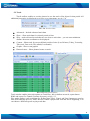
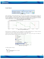
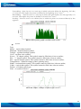
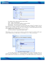
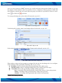
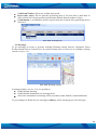
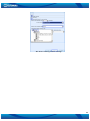
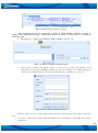
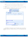
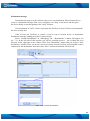
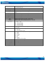
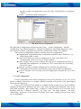
1
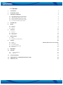
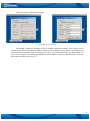
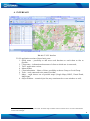
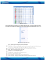
TAVL4 application user manual V1.3 DRAFT 1. Contents 1. CONTENTS 1 2. INTRODUCTION 2 3. GETTING STARTED 3 3.1 3.2 3.3 3.4 3.5 RECOMMENDED PC REQUIREMENTS .NET FRAMEWORK INSTALLATION CRYSTAL REPORTS INSTALLATION TAVL APPLICATION INSTALLATION LAUNCHING TAVL APPLICATION 3 3 3 3 4 4. INTERFACE 6 5. MAIN 7 5.1 5.2 5.3 6. OBJECTS TRACK OTHER EVENTS 6.1 6.2 6.3 7. EVENTS GEOFENCING WARNINGS MESSAGING 7.1 7.2 8. SMS GARMIN FUNCTIONALITY TOOLS 8.1 8.2 8.3 8.4 8.5 VIEW GROUPING CONFIGURATION BULK CONFIGURATION SETTINGS 7 9 12 12 12 14 18 20 20 24 30 ERROR! BOOKMARK NOT DEFINED. 30 34 36 37 9. REPORTS 39 10. FILTER 39 10.1 10.2 FILTER OBJECTS FILTER 39 40 11. LOCALIZATION 41 12. FREQUENTLY ASKED QUESTIONS (FAQ) 42 13. CHANGE LOG 43 1 2. INTRODUCTION TAVL application is software used to connect to the server and retrieve and display information that FM1100, FM1200, FM2200, FM3100, FM3200, FM4100, FM4200, FM5300 or/and GH 1201, GH 1202, GH 3000 stores there. TAVL user manual provides information to fully understand and operate TAVL applications basic functions. Here you will find application installation guide, interface, reports, configuration and event description, operation list. Note, that some operations or functions are not included in base version, but they can be enabled or disabled by server provider. WARNING: Teltonika reserves the right to change/add/remove functions. Also images and functions can be different from presented in Manual. Copyright © Teltonika 2013 All rights reserved. Reproduction, transfer, distribution or storage of part or all of the contents in this document in any form without the prior written permission of Teltonika is prohibited. 2 3. GETTING STARTED 3.1 Recommended PC requirements TAVL application runs on a PC with MS Windows XP (x86) with Service Pack 3 or later, MS Windows Vista (x86 & x64) with Service Pack 2 or later or MS Windows 7 (x86 & x64). MS .NET Framework v3.5 Service Pack 1 and Crystal Reports are also necessary components1. Personal Computer Requirements: Supported Architectures: 32-Bit (x86) 64-Bit (x64) Minimum Hardware requirements: Pentium IV Computer with 2.4 GHz or faster processor 2 GB RAM (Add +512 MB if running in a virtual machine) 100MB of available hard disk space DirectX 9 capable video card running at 1024 x 768 or higher – resolution display 3.2 .NET Framework installation Download .NET Framework 3.5 SP1 from Microsoft website and install it (url: http://www.microsoft.com/downloads/thankyou.aspx?familyId=ab99342f-5d1a-413d-831981da479ab0d7&displayLang=en. If the download doesn't start automatically, click on the "Start Download" button. 3.3 Crystal Reports installation Download and install Crystal Reports for .NET Framework http://avl1.teltonika.lt/downloads/tavl/Crystal%20Reports/CRforVS_redist_install_32bit_13_0.zip 3.4 TAVL application installation Download and extract latest available version of TAVL application (for more information contact one of our sales managers). 1 If TAVL Installer were used, all required software will be installed automatically. If only application used, all components must be installed. 3 3.5 Launching TAVL application You can enter TAVL client application as: User – has basic permissions. User see devices which is assigned to it only. Power User – have advanced permissions. Power User can see all devices from all groups. Administrator – have more advanced permissions (including User and Power User permissions and more), can connect to any user on the server, often this permission has owner of the server. Launch tavl.exe ( ) and enter your user name and password2, see pic. 3.1: Pic. 3.1. TAVL application initial window Additional settings can be found after clicking and language, see pic. 3.2. button: client name, destination server Pic. 3.2. TAVL application additional settings Client name – name of client you are trying to connect, if you are user or power user. Note: you may leave “Client” empty if connecting as administrator. 2 User name and password must provided by server provider 4 Also you can set Connection Settings: Default Connection Settings Proxy Connection Settings Pic. 3.3. Proxy settings By default Connection Settings are set to default connection settings, but if proxy server used to access the internet then in Address field type the IP address of the proxy server and in Port field enter the port number that is used by proxy server for client connections (by default 8080). If proxy server requires User name and Password, tick checkbox “Requires authentication” and enter user name and password, see pic 3.3. 5 4. INTERFACE Pic. 4.1. TAVL Interface TAVL application consists of these basic parts: 1. Quick menu – possibility to add most used functions to reach them as fast as possible; 2. Client name – information about name of client to which user is connected; 3. TAVL application version; 4. Menu toolbar; 5. Client information – Name of client, possibility to choose Group or Local Group. 6. Tools – tools connected to the name of toolbar; 7. Maps – could choose one of possible maps (Google Maps, BING, Virtual Earth, Map Point)3 8. Object Window – contain object list, may contain track or event windows as well; 3 On our server only Open Street Maps are used. All other maps could be used on Clients server. For more information contact sales manager. 6 5. MAIN 5.1 Objects Object window contains a list of all available objects that are available for the client. It is loaded with TAVL application by default, if you close the window and want to see it again you need to click “Objects” button in Main ribbon (see pic. 5.1). Pic. 5.1. Main Object – show objects list; Refresh – refresh objects list showing last possible possition of them; Zoom mode – used to zoom map after each refresh. Available three options: zoom all objects (all objects shown on map), follow concrete object (zoom to one choosen object) or turn off (no zoom mode used); Auto refresh – auto refresh objects list, refresh interval is configured in common settings, When objects list loaded, left to the “Number” column in objects grid is colored rectangular, which indicates the state of object (table 1): Table 1. Vehicle status indication Color RED GREEN YELLOW PURPLE State Idle Moving no FIX4 For some configurable amount of time no data came to server or when device first time attached to user and TAVL application loaded Date/Time column shows timestamp for the latest coordinate received from device along with other additional properties (for example: Speed, Comment, Ignition and ect. 5), see pic. 5.2. Sorting could be done by any column as in ascending order as in descending too. 4 Visibility of sattelites To see this properties configurations on FM(GH) (look at FM(GH)user manual) and server management (TAVL management) must be done. 5 7 Pic. 5.2. Objects list After clicking 'Objects' in toolbar, TAVL displays them on a map. Left-click on the object in the list centers view on that object. Right-click on the object displays the following menu, see pic. 5.3: Pic. 5.3. Object right-click menu Info – displays object information entered in database; Edit Object – ability to modify object number and comments for login with Administrator or Power User rights, login with simple user rights can only add comment. Local grouping – ability to group objects from list into groups for every user; Hide – hides current object from visible list; Unhide All – reveals all hidden objects Configuration – opens object configuration menu; Geofence – opens Geofence menu; Routes planning – ability to plane route by adress points. Send Command – displays available SMS commands for FM series devices; 8 5.2 Track 'Track' toolbar, enables to set time interval to see the track of the object for that period. All additional properties are displayed as well for every timestamp, see pic. 5.4. Pic. 5.4. Track toolbar Advanced – Include advanced track data Show – Show track data for selected period of time Skip – used to discard records that are too close to each other – you can enter minimum distance between coordinates to be displayed. Custom – Show track for one predefined periods of time (Last 24 hours, Today, Yesterday, This week, Last week, This month, Last month) Graphs – Show event graphic Planned routes – Show planned routes on track Pic. 5.5.Track functionalities Track window enables also such options as Track Play, Info in balloon on track, export data to KML and create Geo Tunnel (Geozone by route), see pic. 5.5. Play mode displays each coordinate for defined time. 'Play', 'Pause' and 'Stop' buttons are used to start, hold and stop preview, while 'Reverse' button replays track from the end to beginning. You can choose 6 different speeds to play track data. 9 Graphic Reports Pic. 5.6 Graphs After generating a track of the object you can open a new window with all properties changes in time scale graphics – speed, power voltage, CAN bus information, etc. Information provided here is same as displayed in 'Track' window, except that it is in graphic mode. Left-click on a record in 'Track' window shows a vertical line on a graph at specified timestamp, see pic. 5.7. Pic. 5.7. Graph vizualization Some functions to manipulate the view of graphics are available. Middle button of a mouse increases or decreases the scale of timeline, right-click displays a view settings menu. Image can be copied to clipboard, saved as picture format(*.emf, *.png, *.gif, *.jpg, *.tif, *.bmp), set page setup before printing or sent to printer, see picture 5.8. Pic. 5.8. Graph settings Available graphics settings: Line Show – enable/disable line on Graph Fill – fill the graph Step type: 10 ForwardStep – draw the curve as a stair-step in which each point defines the beginning (left side) of a new stair. This implies the points are defined at the beginning of an "event." ReawardStep – draw the curve as a stair-step in which each point defines the end (right side) of a new stair. This implies the points are defined at the end of an "event." NonStep – draw the curve as an ordinary line, in which the points are connected directly by line segments Pic. 5.9. Example of graphic when fill data is eneble .Symbol Type: Square – square-shaped symbol; Diamond – rhombus-shaped symbol; Triangle – equilateral triangle symbol; Circle – uniform circle symbol; Xcross – "X" shaped symbol. This symbol cannot be filled since it has no outline; Plus – "+" shaped symbol. This symbol cannot be filled since it has no outline; Star – asterisk-shaped symbol. This symbol cannot be filled since it has no outline; TriangleDown – unilateral triangle symbol, pointing down; Hdash – horizontal dash symbol. This symbol cannot be filled since it has no outline; Vdash – vertical dash symbol. This symbol cannot be filled since it has no outline; Default – a Default symbol type; None – no symbol is shown. Pic. 5.10. Graphic example of symbol type Circle 11 5.3 Other Route Planing Route planning is available on TAVL. There are two different kinds of route planning. From last object location to destination point; From point A to point B (user can add more than 2 points by adding additional route stops); Start planning route. Click “Main” and “Routing” (see figure 1) Fig. 1 Route planning menu bar When routing is selected user can start to plan your own route. Write your destination points and click “search for route”. Additional point can be added by selecting “Add route stop”. (see figure 2) Fig. 2 Route planning When all data is set click “Search for route”, trip duration and distance will be calculated below menu bar. Route will appear on the map. 6. EVENTS 6.1 Events To get event notifications in TAVL application press F9 and in opened Settings window in Events settings enable following (see pic. 6.1): Sound on events – enables sound in TAVL application when event occures; Trace event – when event ocures a window will be oppened with event information; Trace events interval – time interval when TAVL application checks for events. 12 Pic. 6.1 TAVL settings window To get event indication in TAVL application FMXXXX or GHXXXX module must be configured first. To configure module right mouse click on object and select configure. Module configuration has the same functions like base configurator. When configuration is made for the first time, all parameters (system, GPS, GSM, GPRS, SMS, Send parameter, Accelerometer, I/O) must be configured. When configuration is done press ΄Save Full‘ and wait, after some time configuration will be send to the device. It is possible to check configuration update status pressing refresh, see picture 6.2 . Pic 6.2. Module selection 'Event Configuration'menu allows configuring events for IO elements. In the picture a sample is shown how to configure Ignition event that will send email to defined recipient. Choose an IO lement from available in 'Available Events' window (more can be added by enabling IO elements in database) and click 'Add'. Enter minimum and maximum values and condition like do this before in I/O elements configuration in the fields. 13 Press ΄Details΄ in ΄Event Adress΄ field write GSM numer for sms or email adress, select transport format and write message text.When press ΄Save Changes΄ and wait, after some time configuration will be send to the device. You can check it by pressing refresh.When current value of IO elements drops below or raises above defined range, a email or sms will be sent to the recipient entered in 'Event Address' field, see pic. 6.3. Note. It is also possible to get events messages in Warning console (see warning console chapter of manual). Pic. 6.3. Event configuration Select Events tab and press find (pic. 6.4) event window will be oppened, where all the events will be shown (pic. 6.5) Pic. 6.4. Events tab Pic. 6.5. Events window 6.2 Geofencing GeoFence When coordinates are sent to the server, they are proceeded using application’s algorithms. If coordinate is in the specified area, a notification can be sent. In the toolbar click 'Events' – >'zones', see pic. 6.6. 14 Pic. 6.6. Geofencing tab Zone creation In the Zone window, see pic. 6.7, select New (1). Enter the name for the new zone (2) and then add some comments in the Comment’s line. Checkbox Enabled enables or disables geozone. If group of geozones is created in the line Zone group you can select it from the drop-down list to the right. Enter Margin value. This value shows how far the object has to go away from the defined geozone (in meters) for the action to be taken (the event to be generated). Choose a shape for your new geozone in Type line (3a) and enter the coordinates. It can be a square, a circle a polygon and road. To get the coordinates for the particular place on the map, to create a new geozone, click on the dotted square icon (3b) and then draw a shape on the map where you need your new geozone to be. T-AVL application will get the coordinates automatically. Then save new geozone (4) Pic. 6.7. New Geozone creation In order to get a warning when a certain object enters or leaves the determined zone the Warning Recipients, Warning Policies and geofencing rules must be configured (see pic. 6.8). Pic. 6.8. Warning recipients and policies In Warning policies, see pic. 6.9, create new policy (1), then pick a name (2), and save new warning policy 15 Pic. 6.9. Warning policies In warning policies setting of sending could be made: Name – name of warning policy Retry – number of retries when sending of warning is failed Retry timeout – time between retries (in minutes) Flood timeout – time (in minutes) to prevent exactly same warning. For example, if you set Flood timeout to 5 minutes, warning was sent and exactly the same warning(type, object, message, client, text and so on) will true to be sent, TAVL will ignore it. If after Flood timeout will come same warning as before, it will be sent. Comment – you can leave a comment about new policy Also you can choose to what group assign the policy. In Recipients, see pic. 6.10, create new recipient (1), then write a name for it, decide on policy type (email or SMS) and write GSM number or email address (3, 4, 5). Then save Recipient Pic. 6.10. Warning Recipients You can name recipient, choose how to inform it (SMS or Email), depending on how you will have to enter GSM number (i.e. +370XXXXXXXX) or email address. Valid hours show the time at which TAVL are allowed to send warning. To send SMS modem must be connected to 16 server or server must use SMPP6 protocol (we would not discuss this question further as it is not the purpose of this manual). Also it is possible to leave a comment or choose group to which add this recipient, recipient may be in more than one group. In toolbar it is possible to choose to create new ( ) or delete old ( ) recipient. To create geofencing rules select rules in Events tab, see pic.6.11: Pic. 6.11. Geofencing rules Geofencing rule creation, name it and asingn objects for this rule, see pic. 6.12: Pic. 6.12. Objects tab Select zones for rule (several Zones or Zone Groups can be selected), see pic. 6.13: Pic. 6.13. Zones and Zone Groups tab When objects, zones and zone groups are assigned for the rule, the last thing to do is to configure when warnings will be generated (‘Warnings’ tab, see pic. 6.14): Recipient: Select a recipient the geofencing warning will be delivered to Warning Policy: Select a warning sending policy you created in previous steps Transition: Select when geofencing warnings will be generated: Any: A warning will be generated when vehicle either enters or leaves the geozone. Inside: A warning will be generated when vehicle enters geozone. Outside: A warning will be generated when vehicle leaves geozone 6 SMPP – Short Message Peer-to-Peer 17 Valid from/Valid to: Select rule validity time period Reject older (days): Do not generate geofencing alerts if received data is older than 30 days (vehicle has crossed geozones later than the defined allowed number of days) Confirmation: A confirmation will be required from the recipient when geofencing alert is delivered. Pic. 6.14. Warnings tab 6.3 Warnings To get warnings on events or geozone warnings Warning console must be configured. Select Events tab and click on Console icon. In console window pres on Gear icon to configure warning console, see pic. 6.15. Pic. 6.15. Warning console In settings window, see pic. 6.16, it is possible to: Enable/disable warnings Enable/disable automatical new warning check Select how information of warning will be presented (sound, balloon, sound and baloon) To get warnings set Watch for new warnings as allways, and in warning types select All types 18 Pic. 6.16. Warning console settings 19 7. MESSAGING 7.1 SMS7 SMS operations There are four types of SMS operations: Sending/receiving SMS messages to/from virtual drivers; Sending SMS user templates; Object location request; SMS predefined commands sending; SMS mailbox can be found in “Messaging” section, see pic 7.1. SMS mailbox has two tabs: “SMS Mailbox” and “Object Location Request”, see pic. 7.2. Pic. 7.1. SMS Pic. 7.2. SMS Window In “SMS Mailbox” tab received and sent messages can be reviewed using date filter. User can select date interval: “Date from”, “Date to” and click “Refresh” for filtering SMS messages sent and received during that period, see pic. 7.3. 7 This functionality is not free. For more information please contact your sales manager. 20 Pic. 7.3. SMS Messages (Inbox/Outbox) New messages also can be composed in SMS SMS Mailbox window. In order to compose and send SMS message, virtual driver has to be created. Virtual driver is created by following steps: 1. Press green “+” sign in the middle of “SMS” window, see pic. 7.4. Pic. 7.4. Driver's window creation invoke 2. “New driver” window will appear. There is other way to invoke this window, more information in 8 chapter. Mandatory fields that need to be filled in for SMS sending are “Name” and “GSM number”. Fill in those fields and press “Add driver”, see pic. 7.5. Pic. 7.5. New Driver Creation Window 'Drivers' allows a user to create virtual SMS receivers. These receivers are used in following cases: 1. To enter a vehicle driver name and GSM number for a possibility to send SMS from TAVL application; 21 2. To enter a device number and GSM number for a possibility to send FM commands to the unit; 3. To enter object number or driver name and iButton ID or RFID for identification. After virtual driver is created, it will be available in the virtual drivers list and you can compose and send SMS: Select “SMS Mailbox” in “Messaging section”, enter text that you want to be sent in “SMS Message Text” field and choose virtual driver from available list, see picture 7.6. Pic. 7.6. Message Writting If same SMS text is used frequently, it can be saved as template. In order to create template, in “SMS Mailbox” window in “User templates” field click “+” sign and new window will pop-up. In this window enter “Template name”, “Message text” and press “Save” – new User template will be created, see pic. 7.7: 22 Pic. 7.7. Template Creation Table “Object Location Request” tab can be used to get location of objects, see pic. 7.8. Three request types are possible: Get 24 coordinate – requests object to send 24 coordinate SMS to server; Get Location – requests last stored GPS data to be sent to server; Flush using GPRS – requests all available records in FM series device memory, to be sent to server; Pic. 7.8. SMS Request After successful request new data about objects position will be available in TAVL application – position on map and data in “Objects” window. “Send Command” allows user to send predefined commands to FM units, see pic. 7.9. Commands are entered on in database using Management interface. SMS commands can be sent to objects by clicking right mouse button on object while operating in “Objects” window. Between options that appear, “Send command” and command itself can be chosen. Sent commands and answers to these commands can be reviewed in “SMS Mailbox”. Pic. 7.9. SMS Commands 23 It is possible to send the same command to multiple objects. To send SMS command to more than one unit, the SMS command must be common to these units. 7.2 Garmin functionality TAVL client application lets user to use the following features of GARMIN FMI: 1. Text messaging; 2. Destination message; 3. ETA request; Text messaging Text messaging feature lets user to communicate with driver (user that uses Garmin device) by sending text messages via GPRS. Message sending procedure is shown below: Select “Garmin Mailbox” in “Messaging” tab – “Garmin Mailbox” window will appear, see pic. 7.10. In top of window you will have Date filter for filtering messages sent/received messages. In the bottom part of window click “Send New Message” – “Send Garmin Message” will pop-up. Here you can select one or multiple objects with Garmin devices and enter message text that will be sent to Garmin device. Pic. 7.10. Garmin Text Messaging 24 Destination message Destination message is used to inform a driver of a new destination. When Garmin device receives a destination message from server it displays it as “Stop” to the driver and also gives the driver ability to start navigating to the “Stop” location. New destination in TAVL client is represented as GeoZone so new GeoZone (as destination) has to be created first. After at least one GeoZone is created, it can be sent to Garmin device as destination. Destination message sending procedure is shown below. Select “Garmin Destinations” in “Messaging” tab - “Destinations” window will appear, see pic. 7.11. In the left side of this window you will see available devices – one of them has to be selected. In the right part of the window click “New Destination” button and you will get “New Destination” window. Here you need to select previously created GeoZone and optionally create a comment for this destination. After this click “Save” and new destination will be saved. Pic. 7.11. Garmin Destination 25 After saving destinations, “Synchronize“ button has to be pressed in “Destinations“ window in order to send selected destinations to Garmin device. “Refresh” button needs to be pressed to update information in “Destinations” window. ETA request message ETA (Estimated Time of Arrival) request message is used when user wants to know expected arrival time to currently active destination in Garmin device and distance (in meters) from current object location to currently active destination. ETA requesting in TAVL client interface is shown below. Click “ETA” in “Messaging” tab - “ETA Request” window will appear, see pic. 7.12. Available objects will be shown in this window – select one or multiple devices and press “Request ETA” button. After a while you will get information about estimated time of arrival and distance from object to current destination in Garmin device. “Show on Map” button can be clicked in order to see current position of the object. “Refresh” button needs to be pressed to update information in “ETA Request” window. Pic. 7.12. Garmin ETA GPRS It is possible to send GPRS commands to FM5300 using TAVL application. When FM5300 sends records periodically to a server, a message could be sent from the server and FM5300 will reply to it. GPRS commands list can be found in Messaging tab -> GPRS window (pic. 7.13) Pic. 7.13. GPRS commands menu 26 To send GPRS command need press “Commands” icon (Pic. 7.14), select object to which need send command (pic. 7.15), press “Next”, select command from the list and press “Send”. Available GPRS command list and description show in table 2. Pic. 7.14. Object and module type window GPRS mail box, see pic. 7.15, allow monitor situation and check history about sent and received GPRS command for selected period. Pic. 7.15. GPRS commands mail box Note: FM5300 has to be connected to the server in order to receive commands. Table 2 . GPRS commands and description Command Description #GET DATAORDER Get info about records sorting parameter #SET Set records sorting parameter, X – profile, Y – value (0/1). 27 DATAORDERX=Y #GET RECTO #SET RECTO=X #GET VERSION #GET NETWORK #GET IMSI #GET OUT #DO REPORT #DO RESET=XXX #GET ROAMINGX=Y #SET ROAMINGX=Y,Z #GET REMIPX #SET REMIPX=Y:Z #GET AUPX #SET AUPX=Y,Z,W #GET REPRTX #SET REPRTX=Y #GET REPDISTX #SET REPDISTX=Y #GET REPANGX #SET REPANGX=Y #GET SENDPERIODX #SET SENDPERIODX=Y #GET REPMRX #SET REPMRX=Y #GET IBTNX #SET IBTNX=Y,Z #GET EXTERR #SET EXTERR=X getstatus getweektime getops readops# Get info about records refresh timeout parameter Set records refresh parameter, X = records refresh timeout Receive firmware version Get GSM operator to which device is connected Get IMSI of the device Get DOUT values Save a record Reset FM5300 or GPS module, XXX – FM5X or GPS Get operator from the list of a certain profile, X – profile, Y – operator number in a list Set operator to the list of a certain profile, X – profile, Y – operator number in a list, Z – operator code Get IP and port number from the configuration of a certain profile, X – profile Set IP and port number to the configuration of a certain profile, X – profile no, Y – IP or domain, Z – port number Get APN, user login and password from the configuration of a certain profile, X – profile Set APN, user login and password to the configuration of a certain profile, X – profile, Y – APN, Z –, user login W - password Get MinPeriod from the configuration of a certain profile, X – profile Set MinPeriod to the configuration of a certain profile, X – profile, Y – MinPeriod value Get MinDistance from the configuration of a certain profile, X – profile Set MinDistance to the configuration of a certain profile, X – profile, Y – MinDistance value Get MinAngle from the configuration of a certain profile, X – profile Set MinAngle to the configuration of a certain profile, X – profile, Y – MinAngle value Get SendPeriod from the configuration of a certain profile, X – profile Set SendPeriod to the configuration of a certain profile, X – profile, Y – SendPeriod value Get MinRecords from the configuration of a certain profile, X – profile Set MinRecords to the configuration of a certain profile, X – profile, Y – MinRecords value Get iButton value from the configuration of a certain profile, X – profile Set iButton value to the configuration of a certain profile, X – profile, Y – number on the list, Z – iButton value Get extended errors value Set extended errors value, X – 0/1 Modem Status information Current device time, Day of Week and amount of minutes passed since start of week List of currently used and available GSM operators Emergency gsm operator readout from active profile # - 1,2,3 1 – operators [1-20] 28 getnmeainfo getcfgtime getgps loadprofile# cpureset resetallprof getver getinfo deleterecords getio readio # setdigout XXXX Y1 Y2 Y3 Y4 getparam # setparam # # flush #,#,#,#,#,#,# sn x [x=0;1] banlist crashlog delete_all_sms braminfo getgnss 2 – operators [21-40] 3 – operators [41-50] Nmea error debug sms Date and Time of last successful configuration Current GPS data and time Load specified profile into RAM Engine Profile. # - number of profile to load Reset CPU Reset all FLASH profiles to default profile Device / Modem / Code version information Device runtime system information Delete all records saved on FLASH Readout digital inputs and outputs, analog inputs Readout input value according entered ID, # - ID value Set digital outputs 0 – OFF, 1 – ON Y1 – timeout for DO1 Y2 – timeout for DO2 Y3 – timeout for DO3 Y4 – timeout for DO4 Readout parameter value according entered ID. # - ID value. Set parameter value according entered ID and Value. 1.# - ID value. 2.# - New Parameter Value Initiates all data sending to specified target server 1.# - IMEI 2.# - APN 3.# - LOGIN 4.# - PASS 5.# - IP 6.# - PORT 7.# - MODE (0-TCP/1-UDP) Enable/disable static navigation Banlist information Crash log information Delete all read SMS BatRam info Current GNSS information 29 8. Tools 8.1 Grouping8 TAVL server administrator can allow or deny 'Power User' to use Grouping feature. This feature can define that certain object or driver belongs to certain group and the simple user, which belongs to the same group can see only those objects, while Power User can see all available objects, see pic. 8.1. Pic. 8.1. Grouping Like you can see above grouping feature have several dedicated buttons: 'Groups', 'Users', 'Drivers' and 'Objects'. Each button function is activated by mouse click on it. Main function is ‘Groups’ - it allows creating dedicated groups for each user, to which can be attached users, drivers or/and objects. Simple steps to create new groups: 1) Grouping > Groups > Add new (pic 8.2) Pic. 8.2. Add new Group 8 Not for simple user with Simple right, for more information contact sales manager. 30 2) And you will jump to table ‘Details’ where you must type information about your new group (pic. 8.3): Pic. 8.3. New Group Description 3) Push ‘Save’ icon. 4) Result (pic. 8.4): Pic. 8.4. Created Groups First decide which created users will be available for a User. Power User is allowed to create groups. Each user can be assigned to different groups. Power User can create a simple user logins for TAVL application (click Users button in the toolbar and select 'New'). Each simple user can be assigned to different groups. User grouping is available from Tools -> Grouping -> Users. The new user will be able to see only those objects that match his group, see pic. 8.5. Pic. 8.5. User Grouping 31 TAVL application can also store a driver list with assigned GSM numbers and it is possible to communicate with those drivers using SMS (see SMS Communication chapter for more information). Just like objects, each driver can be assigned to different groups too. Driver grouping is available from Tools -> Grouping -> Drivers, see pic. 8.6. Pic. 8.6. Driver Grouping Power User is allowed to create groups. Each Object can be assigned to different groups. Select objects one by one and assign a group to it. Note, that more than one group is available for one object. Object grouping is available from Tools -> Grouping -> Objects, see pic. 8.7. Pic. 8.7. Object Grouping Local grouping Local grouping - feature dedicated for ‘Simple User’. Function which is used in local mode. Local grouping gives possibility for user esasy create group and attache to it one by one objects from object list. To add new group move mouse on the object which you like and push right mouse button on it and you will see available functions list then go Local grouping > Add new, see pic. 8.8. 32 Pic. 8.8. Local Grouping New window with empty field pops-up where you can fill in group which you want to add, see pic. 8.9. Pic. 8.9. Add new local group And then new group will appear in available group list, see pic 8.10. This group will be already attached to object which you choice 33 Pic. 8.10. New Local Group When group is created it can be attached to all objects one by one. To ‘Delete” group uncheck it in all objects and then it will be not in use group will be erased automatically. If group is dedicated minimum to one object it can not be deleted. 8.2 Configuration Module Configuration TAVL application has an interface for remote FM configuration via GPRS and SMS. Note, that current SMS username and password saved on FM device configuration must match values entered on TAVL database, else all configuration attempts will result failure. Remote configuration can also be done by sending simple text SMS to the module with special commands (see FMxx user manual for more details). In the object list right-click on the object and choose ‘Configuration’, see picture 8.11. On the left side of configuration windows user can see a list of available configurations for module with different status. These can be: ‘Active’ – currently available configuration. Note, that when new object is added, server does not receive configuration from FM device and all fields are left blank. ‘Active’ configuration will show currently used values only when FM device is configured with TAVL application. ‘Template’ – this is a template configuration. ‘Template’ settings are not stored in FM device, they are stored on server. A selected configuration can be saved as template for one or mode modules. ‘New’ – new configuration is displayed when new settings are about to be sent to the device. ‘Synchronizing’ – a configuration that is queued for update. When saving new settings (configuration), new configuration is renamed to ‘Synchronizing’ until process is successful or time-out expires. If configuration is successful, then ‘Synchronizing’ is renamed to ‘Active’ and new data can be seen indicating when it 34 became available. If configuration is not successful, ‘Synchronizing’ is renamed to ‘Failure’. ‘Failure’ – last unsuccessful configuration. Pic. 8.11. Device Configuration The right side of configuration windows has three parts - ‘Event Configuration”, ‘Module Configuration’ and ‘Global Parameters’. ‘Module Configuration’ and ‘Global Parameters’ have same interface as FMxx configurator described in particular device FMxx User Manual. The bottom of configuration windows consists of tools for configuration: ‘Send Method’ field identifies how configuration should be sent to FM device – by GPRS, binary SMS, or both. ‘Save Full’ button saves selected configuration as ‘New’ and renames it to ‘Synchronizing’ when server tries to contact module. ‘Save Changes’ only saves new changes since last active configuration, but have in mind, that first configuration for module on TAVL always has to be saved using ‘Save Full” option. ‘Refresh’ refreshes available configuration list. This does not read current configuration from module, only refreshes status of all available configurations. ‘Save as Template’ saves currently selected configuration as template for one or more objects. 1. Event Configuration 'Event Configuration' menu allows configuring events for IO elements, see pic. 8.12. In the picture a sample is shown how to configure Ignition event that will generate event when Digital Input will enter High level. Choose an IO element from available in 'Available Events' window (more can be added by enabling IO elements in database) and click 'Add'. Enter minimum and maximum values in the fields 'Min' and 'Max' – these define range. ‘Condition‘ is same parameter as IO ‘Generate Event‘ parameter and has 5 different selections: ‘On range exit’, ‘On range entrance’, ‘On both’, ‘Monitoring’, ‘Hysteresis’. Event can be set as Panic Event. Also, Validity period of event can be set on configuration. 35 Pic. 8.12. Event Configuration 8.3 Bulk configuration TAVL configuration can be performed for several objects at the same time by TAVL administrators and Power users. Bulk configuration is available in Tools -> Bulk Configuration, see picture 8.13. Bulk configuration can be created, edited or deleted by right-clicking in 'Bulk Configuration' window and selecting an appropriate action. The same rules apply to configuration methods as in simple configuration: there are tree available configuration send methods: GPRS, SMS and GPRS or SMS. There are two send types available to send: full configuration or only difference between bulk and native module configuration (native module configuration should be performed using TAVL application. If you are not sure if module were configured using TAVL application, please select send type 'Full'). Pic. 8.13. Bulk Configuration 36 8.4 Settings Settings window allows you to customize TAVL applications settings. In the Tools -> Settings, see pic. 8.14, menu choose ‘Common’ button or hit F9 on keyboard to configure parameters, see pic. 8.15. Pic. 8.14. Settings Following parameter can be edited: 1) Data Representation a) Measure system – allows to choose measurement system for metric or imperial. b) Stop Speed – maximum speed value when object is treated as not moving. This is used when coordinates error occurs and object is displayed on new location. If speed will not be exceeded configured value, object will not change its location. 1) Driver info menu allows choosing either to show or not driver information in Objects window. Driver info can be acquired with: a) iButton; b) RFID; c) Tachograph. 2) Events. a) Sound on new event – enabled or disabled sound used for warnings b) Trace event - sets if program should automatically check for new events. c) Trace events interval - sets the period in seconds for new events checking. 3) Geofence a) Always Show Geozones - let you choose to show or not Geozones on map. Pic. 8.15. Common Settings b) Show geozone names on map – sets whether to show or not geofence names on map. If several geofence zones were created without names, it will be numbered. 4) Map 37 a) Draw only on active map – sets if track should be drawn on currently active map only or on all available maps. b) Exclude engine off points – excluded points in drawn track, where vehicle engine was off. c) Max speed between two adjacent points in track – program automatically calculates speed between two adjacent points (distance between points divided by elapsed time). If speed will be greater than this parameter, second point will not be shown in track. d) Min distance in track – if distance between points in track will be shorter than this parameter set second point will not be shown in track. e) Min distance in track when engine is off – same as ‘Min distance in track’ except that points is being removed only then engine is off. f) Min satellites in map – if record was made with lower number for satellites then this parameter then this point will not be shown in track. g) Min stop time to show stop point in track – time interval after which if all stop conditions are true object is treated as not moving. h) Object symbol size – determines object symbol size on map. It can be: Small, Big or Modern. i) Optimized map centering – if you will choose yes, map will be centered only when object is not visible in currently displayed map otherwise map will be centered always when you select object in object window. j) Route line color – sets route line color. k) Show address on map – lets you choose either to display address in pop up window next to object symbol. l) Show coordinates on map - lets you choose either to display coordinates in pop up window next to object symbol. m) Show geofence entries in track – sets either to show or not symbol on track when object enters or exit geofence zone. n) Show information about all intermediate stops – allows to display information in pop up window about stops in track where object was considered as not moving o) Show intermediate stop point – allows to display stops in track where object was considered as not moving p) Show object numbers on map – let you choose either to display or not object numbers on map even then object is not selected. q) Track line color – sets track line color r) Use Median Track Speed Filter – sets to use median filter to average speed while using track play function. s) Zone fill color – lets you choose geozone, which is displayed on map, filling color. 5) Misc a) Auto refresh interval - allows to set time interval in seconds to refresh the object window and map automatically. 38 9. REPORTS TAVL application has ability to generate statistic reports based on GPS data and/or external sensors or properties. These reports can be launched by clicking 'Reports' and choosing one of available. 10.FILTER Filtering enables object and data filters refine the information, see pic. 10.1. Pic. 10.1. Filtering 10.1 Filter Objects Loading lots of objects takes more time and sometimes it can be very confusing. Filtering lets you choose which object you want to view, and hides the rest. When refreshing objects, data is sent only about those that are marked, so it takes less time. In the TAVL toolbar click on 'Filter' or hit Ctrl + Shift + F, see pic. 10.2. Pic. 10.2. Object Filtering 39 In the new window click on object you want to be displayed and click 'Ok', see pic. 10.3. Before filtering 10.2 Pic. 10.3. Filtering Results After filtering Filter Pic. 10.4 Data Filtering To check which object do not send data or send rarely takes more time and sometimes it can be very confusing. Filtering lets to see which object do not send data for set period or send rarely, see 10.4. Filter type can be: No Data (able set data type: any or send other GPRS) or Less Data (able set message count by period) 40 11.LOCALIZATION TAVL language localization tool is used to build localized (translated) version of TAVL application. On excel file you will find all fields in english language, make changes on this file - translate each field named in english to desired name in your language. Localization will be completed by compiling this file. For more information and excel file for localization, please contact your sales manager. After Localization when you run the TAVL application, you will be able to set new language. 41 12. FREQUENTLY ASKED QUESTIONS (FAQ) 100 Horizontal Probability, % 1. Why doesn't objects trail match roads that are shown in the map? What is the accuracy of GPS? 80 Vertical (altitude) 60 Object trail doesn’t coincide Error Hor. Alt. with roads shown in the maps because 40 CEP (50%) 2.9 m 4.1 m of GPS limited accuracy. GPS accuracy 95% 6.9 m 13.7 m depends on location (geographic 20 99% 10.1 m 19.6 m latitude, longitude), satellites’ location and ionosphere’s conditions. In perfect 0 conditions (sunny weather, no clouds, 0 2 4 6 8 10 12 14 16 18 20 in open area, without skyscrapers, Distance, meters woods) accuracy can be about 3 – 5 meters. Usually accuracy is estimated using statistical method CEP (Circle of Equal Probability). This method allows us to consider, that in probability of 50%, object’s coordinates’ error does not exceed designated values. Otherwise, roads in the map not always are defined very precisely (especially considering Eastern Europe). Another possibility is that new roads don’t exist in the map. 2. Why do data transfers from server to application take so long? Duration of data transfers from server to user application depends on amount of data and speed of Internet connectivity. While object registers many parameters very often grows data quantity. Then transfer time for long requested period of time could be very long. So if you want to increase data transfer time you should decrease requested data time period. One more way to decrease data transfer time is to decrease frequency of object’s parameters data (time T1 should be not 1 minute but 2 – 3 minutes). 3. Why it is impossible to request current object position? In most cases you are unable to receive information about current object’s location, because it is out of GSM coverage (is in the sea, in deep woods, etc.) 4. It is one or two hours since module sent its data. Why is it not refreshed? Module is sending data to the server at fixed time. If the connection is not possible (there is no GPRS context), the next sending will be at fixed time. Still You can send the request, and get the latest data. Also profile may define data acquirement less often (i.e. every 10 minutes when object is not moving) and settings allow only full packet sending. 5. Why only yesterday’s data is shown? Either module didn't sent data because it's not time to do it or it couldn't send it because of network problems. Solution is to configure module so it sends data at desired time. 6. How can I know objects location if it is not sending data by GPRS? You can send a request and get the SMS with 24 coordinates (see chapter 4.4.4). 42 7. Why is object changing its coordinates even when engine is off? It is because of GPS accuracy. If object is standing between tall buildings or in from of the wall, module doesn't see enough satellites to set its exact coordinates. Then each coordinate is calculated with a slight error. Error depends on number of visible satellites. If object is standing between tall buildings or in front of a wall it may not be enough for module to set its position correctly. 8. I'm receiving incorrect time – it's always same interval ahead or behind current time. This is happening because of incorrect time zone settings on PC. Please choose matching time zone in windows regional settings. 13.CHANGE LOG Nr. Date 1 2013-02-28 New version number 1.0 2 2013-03-01 1.3 Comments Version Draft Release Minor changes 43