1
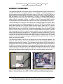
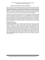
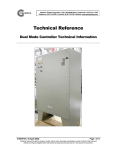
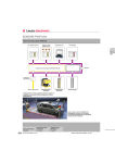
Capstone
CAPSTONE TURBINE
CORPORATION
ADVANCED POWER SERVER (APS)
TECHNICAL REFERENCE
480023 Rev A (June 2007)
Page 1 of 16
Capstone reserves the right to change or modify, without notice, the design, specifications, and/or contents of this document
without incurring any obligation either with respect to equipment previously sold or in the process of construction.
Capstone Turbine Corporation • 21211 Nordhoff Street • Chatsworth • CA 91311 • USA
Advanced Power Server (APS): Technical Reference
Copyright © 2007 Capstone Turbine Corporation. All Rights Reserved.
Publisher
Capstone Turbine Corporation
21211 Nordhoff Street
Chatsworth • CA 91311 • USA
Telephone: (818) 734-5300
Facsimile: (818) 734-5320
Website: www.microturbine.com
480023 Rev A (June 2007)
Page 2 of 16
Capstone reserves the right to change or modify, without notice, the design, specifications, and/or contents of this document
without incurring any obligation either with respect to equipment previously sold or in the process of construction.
Capstone Turbine Corporation • 21211 Nordhoff Street • Chatsworth • CA 91311 • USA
Advanced Power Server (APS): Technical Reference
TABLE OF CONTENTS
PRODUCT OVERVIEW...............................................................................................................5
PRODUCT CAPABILITIES..........................................................................................................6
APS MicroTurbine Control Functionality ..................................................................................6
Operating Features .............................................................................................................. 6
Operational Modes ............................................................................................................. 10
PLC Balance of Plant Functionality....................................................................................... 11
Capstone Remote Monitoring Functionality.......................................................................... 12
PRODUCT PERFORMANCE................................................................................................... 13
APS Controller Performance ................................................................................................. 13
Maximum MicroTurbine Capacity ...................................................................................... 13
Dual Mode Group Transition Time .................................................................................... 13
APS Modbus Command Response Time ......................................................................... 13
Load Following Response Time ........................................................................................ 13
PLC BOP Performance ......................................................................................................... 14
PLC Modbus Master Device Response Time................................................................... 14
PLC Modbus Mathematics Update Time .......................................................................... 14
Remote Monitoring Performance .......................................................................................... 14
Web Page Update Rate ..................................................................................................... 14
Web Page Data Trending Storage Capability ................................................................... 14
PRODUCT CONSTRAINTS..................................................................................................... 14
Product Configurations .......................................................................................................... 14
Electrical Requirements......................................................................................................... 15
Environmental Specifications ................................................................................................ 15
Operation ............................................................................................................................ 15
Storage ............................................................................................................................... 15
Regulatory Specifications ...................................................................................................... 15
Physical Specifications .......................................................................................................... 15
Product Weight ................................................................................................................... 15
Product Dimensions ........................................................................................................... 15
REFERENCE DOCUMENTS ................................................................................................... 16
CONTACTING CAPSTONE APPLICATIONS......................................................................... 16
Capstone Applications ........................................................................................................... 16
480023 Rev A (June 2007)
Page 3 of 16
Capstone reserves the right to change or modify, without notice, the design, specifications, and/or contents of this document
without incurring any obligation either with respect to equipment previously sold or in the process of construction.
Capstone Turbine Corporation • 21211 Nordhoff Street • Chatsworth • CA 91311 • USA
Advanced Power Server (APS): Technical Reference
List of Figures
Figure 1. Internal Views of an APS-115-C001 with Remote Monitoring Hardware.............. 5
Figure 2. Example Facility Site Diagram .............................................................................. 7
Figure 3. Example Facility Website.................................................................................... 12
Figure 4. APS Enclosure Dimensions ................................................................................ 16
List of Tables
Table 1. APS Operating Features vs. Operational Modes ................................................. 11
Table 2. APS Product Configurations ................................................................................ 14
Table 3. Reference Documents ......................................................................................... 16
480023 Rev A (June 2007)
Page 4 of 16
Capstone reserves the right to change or modify, without notice, the design, specifications, and/or contents of this document
without incurring any obligation either with respect to equipment previously sold or in the process of construction.
Capstone Turbine Corporation • 21211 Nordhoff Street • Chatsworth • CA 91311 • USA
Advanced Power Server (APS): Technical Reference
PRODUCT OVERVIEW
The Capstone Advanced Power Server (APS) is the second-generation MicroTurbine multi-unit
controller manufactured by Capstone (internal view in Figure 1). Its primary purpose is to
provide advanced control capability that allows groups of C60 and/or C65 MicroTurbines to
operate with all the benefits of both a collection of individual units and a single aggregate unit.
With the addition of an APS, the functionality of a group of Capstone MicroTurbines is
significantly improved and inherently more reliable compared to a MicroTurbine MultiPac
system without a dedicated controller. In addition to the APS’ enhanced MultiPac control
functionality this second-generation power server has two other significant features built into it.
The first new feature is the ability to communicate with a Building Management System (BMS)
as well as read data from Modbus compatible field devices. The APS can interface with an
existing BMS controller over an RS485 Modbus two-wire network, where the APS is a slave
device with a fully software configurable register map. The APS can also act as a master on a
RS485 Modbus two-wire network that is completely independent from the incoming RS485
network. On this network, the APS can connect to multiple Modbus slave devices to provide
local monitoring and control for balance of plant equipment, such as reading electric power
meters, water flow meters, gas meters, etc. This network is internally connected to a PLC that
is custom programmed by Capstone for the individual customer’s site needs. In addition, this
internal PLC has the ability to interface with digital voltage I/O, analog voltage I/O, analog
current I/O, and analog temperature inputs, giving the APS the ability to handle a variety of
needs a customer may require.
The second new feature in the APS is the optional built in remote monitoring capability. This
allows the APS to become part of an internet-based remote data monitoring, alarming, and
trending service offered by Capstone. The Capstone Service Network (CSN) allows users to
monitor their MicroTurbines and other Balance Of Plant (BOP) devices that are controlled by
the APS from a customer’s site specific web page accessible from the Internet. When an alarm
condition occurs, the user receives an e-mail notification alerting him/her of the issue. This new
remote monitoring functionality also allows Capstone a remote connection that will provide
diagnostic and software update capability from the main corporate customer service center.
Figure 1. Internal Views of an APS-115-C001 with Remote Monitoring Hardware
480023 Rev A (June 2007)
Page 5 of 16
Capstone reserves the right to change or modify, without notice, the design, specifications, and/or contents of this document
without incurring any obligation either with respect to equipment previously sold or in the process of construction.
Capstone Turbine Corporation • 21211 Nordhoff Street • Chatsworth • CA 91311 • USA
Advanced Power Server (APS): Technical Reference
PRODUCT CAPABILITIES
APS MicroTurbine Control Functionality
The APS has a significant level of capability to configure many different operational schemes
for MicroTurbines at a given site. This capability is described below in two separate sections as
Operating Features and Operational Modes.
Operating Features
Internal Heath Monitoring Capability
The APS has an internal function dedicated to making sure that the APS controller is
functioning correctly. If for any reason the APS controller ceases to operate normally, a
hardware reset line will trigger the reset of the APS controller. This reset will trigger anytime that
any internal main process within the controller fails to reset the hardware safety timer within
50 seconds.
Grouping Capability
The APS has the ability to configure up to four groups of C60/C65 MicroTurbines where one
group is a Stand Alone configuration and the other three are Grid Connect configurations. The
Stand Alone group can be a Stand Alone only configuration or it can support a dual mode
system where it includes any combination of the MicroTurbines from any of the three GridConnect groups. When configured for a dual mode system, the active Grid Connect groups will
run as set up and in the event of a power outage will switch over to Stand Alone operation as
configured for the Stand Alone group setup. Clearly, this allows for a great amount of flexibility
in the operation of the MicroTurbines when a power outage occurs.
Each Grid Connect group acts as a separate “virtual MicroTurbine” that can then have
completely independent operating modes compared with the other Grid Connect groups. This
allows the APS to control groups of MicroTurbines in a building that have separate operational
goals and/or separate locations. For example, six units might be set up as a back up group for
a computer room, five units might be set up as a facility electrical load following group and two
units might be on the other side of the building running in Grid Connect heat recovery mode for
process heating or air conditioning as illustrated in Figure 2.
480023 Rev A (June 2007)
Page 6 of 16
Capstone reserves the right to change or modify, without notice, the design, specifications, and/or contents of this document
without incurring any obligation either with respect to equipment previously sold or in the process of construction.
Capstone Turbine Corporation • 21211 Nordhoff Street • Chatsworth • CA 91311 • USA
Advanced Power Server (APS): Technical Reference
Building
Water Feed
Water Meter
Preheated Water
Steam or Hot Water
Boiler/
Hot Water Heater
PCC
(Point of Common
Coupling to Utility)
Main
Service
Panel
Return Water
or feeder
Power
Meter
Modbus
Master Bus
Modbus
Slave Bus
Data Com Bus
CAPSTONE
APS
Building
Management
System
Moxa
Moxa
Turbine Control Com Bus
Thermal Loaded Systems
DMC
Control
Com
Base Loaded
Backup Systems
LAN
Connection
Electrical
Power
DMC
Moxa
Moxa
Moxa
Moxa
Local CRMS
Connection
Internet
Connection
`
Computer Room
(Critical Load)
Electrical Load
Following Systems
Moxa
Moxa
Moxa
Moxa
Moxa
Moxa
Moxa
Figure 2. Example Facility Site Diagram
Start Dispatch Capability
Each group can be set up to have automatic starting logic that determines which MicroTurbines
are started and stopped based on unit capacity and turbine numbering within a group. This
supports the functionality where not all turbines within a group run at the same time.
Run Time Balancing Capability
The APS monitors the operating hours of each MicroTurbines and can automatically control
which units run to equalize the operating hours of the MicroTurbines in a given group. By doing
this, the user alligns the scheduled maintenance of the MicroTurbines in a group.
Electrical Load Following Capability
The APS in Grid Connect mode can automatically control the import of electricity from the
utility. This is accomplished by connecting up a Modbus slave-compatible digital power meter at
the Point of Common Coupling (PCC) with the utility, and using the power feedback to control
the MicroTurbines’ power output. The APS automatically adjusts the MicroTurbines’ output to
maintain the power being purchased from the utility to a level set by the user. This functionality
can only be associated to a single group of MicroTurbines, but other groups of MicroTurbines
can be set to operate in operating modes that allow them to cover the building base load, and
this group can then regulate the power that will be purchased from the utility.
480023 Rev A (June 2007)
Page 7 of 16
Capstone reserves the right to change or modify, without notice, the design, specifications, and/or contents of this document
without incurring any obligation either with respect to equipment previously sold or in the process of construction.
Capstone Turbine Corporation • 21211 Nordhoff Street • Chatsworth • CA 91311 • USA
Advanced Power Server (APS): Technical Reference
Manual Start and Power Override Capability
With any individual MicroTurbine, the user can manually start/stop and/or manually set the
power demand for the unit. Note that manually overriding power demand can only be done in
Grid Connect operation. This can be done while still allowing the currently operating control
mode to function which can be very helpful in troubleshooting facility issues. Care must be taken
to not take too many units away from the controller when operating in an automated control
mode as this may result in unexpected performance of the controller and system as a whole.
ICHP Thermal Load Following Compatibility
The APS acts as a master for each group, and ICHP units can be set up under each group to
operate in electric priority or thermal priority modes. The APS provides additional flexibility when
setting up thermal recovery systems compared to MultiPac systems where a MicroTurbine is the
master. Refer to the C65 ICHP Application Guide (480014) for additional information about how
to set up thermal recovery systems.
Electric Priority with Thermal Tracking
For electric priority mode, the APS provides the electric load following logic and controls power
output of each MicroTurbine accordingly. The thermal output of each ICHP MicroTurbine’s heat
recovery module is determined by the position of its exhaust diverter valve, which is controlled
by temperature measurements and temperature setpoints. These temperature measurements
and setpoints can be done individually at each MicroTurbine (local), or as a group through the
APS. Measurements and setpoints are independent, and can be set for either APS or local
MicroTurbine operation (e.g. the temperature setpoint can be controlled by a user set value in
the APS while the actual measured temperatures can come from each MicroTurbine).
Each ICHP MicroTurbine can measure temperature using its integrated RTDs for inlet or outlet
water temperature, or can accept a 4-20mA signal from an external temperature sensor. This
temperature measuring setup must be done for each ICHP MicroTurbine through the normal
CRMS software or through the local control panel of each MicroTurbine. If the APS is to be used
for a group’s temperature measurement, it may require some PLC programming plus a
temperature input signal source. The source can be from an RTD using the optional PLC RTD
input module, from an external temperature sensor using the optional PLC Analog current or
voltage modules (e.g. 4-20mA), from a temperature sensing system where the APS is acting as
a Modbus master (e.g. a control system for an absorption chiller), or from temperature data
provided by a building management system where the APS is acting as a Modbus slave. This
provides a great deal of flexibility in setting up thermal recovery systems. However, care must
be taken in the system design to avoid situations where the operating mode turns off ICHP units
that need to provide heat recovery, or operates them at low power (thereby limiting the amount
of recoverable thermal energy).
Thermal Priority
For thermal priority mode, each ICHP unit’s exhaust diverter is locked in the full heat recovery
position and thermal output is controlled by adjusting the electric power output. Both
temperature measurements and temperature setpoints must be done at the APS, since the APS
is providing the control commands to each ICHP MicroTurbine in the group to adjust its electric
power output to maintain the desired temperature. As noted above, the temperature
measurement input to the APS can come from a variety of sources, and may require some
custom PLC programming. Likewise, the temperature setpoint in the APS can come from a
variety of sources, including manual user input or dynamic data read from a building
management system where the APS is acting as a Modbus slave.
480023 Rev A (June 2007)
Page 8 of 16
Capstone reserves the right to change or modify, without notice, the design, specifications, and/or contents of this document
without incurring any obligation either with respect to equipment previously sold or in the process of construction.
Capstone Turbine Corporation • 21211 Nordhoff Street • Chatsworth • CA 91311 • USA
Advanced Power Server (APS): Technical Reference
Transition from Grid Connect to Stand Alone Operation
Care must be taken when setting up groups that include Dual Mode units that will switch
between operating modes. The APS allows each group to have its own thermal load following
control schemes, as defined above. However, all switched ICHP units must use the same
temperature measurement and setpoint scheme for both Grid Connect and Stand Alone
operation. For example, if the thermal priority mode is chosen for Grid Connect operation for
ICHP units in groups 2, 3 and 4, the APS temperature measurement and setpoint must be the
same if some or all of these ICHP units are also in group 1 for Stand Alone operation.
If the heat recovery system design requires the Grid Connect groups to operate with different
temperature measurements and setpoints, this can be accomplished by using electric priority
with local thermal load following control at each MicroTurbine for both temperature
measurement and setpoint. This allows the selected Grid Connect ICHP units in each group to
transition to Stand Alone without changing the thermal operating scheme, but maintains the
desired independent thermal load following operation. Note that thermal recovery capacity
from ICHP units operating in Stand Alone will likely be less than when they are operating in
Grid Connect mode.
Dual Mode Compatibility
A single dual mode controller can be connected to the APS to operate a single group of Stand
Alone MicroTurbines in the event of a power outage. The dual mode controller allows the
systems to transition to a Stand Alone power generation system automatically within
10 seconds if the grid power fails, as the APS is compatible with Capstone’s Fast Transfer
functionality. Note that Fast Transfer capability is only provided in C60/C65 software version
4.50 and higher. When combined with a small UPS system to cover the load during this fast
transfer 10-second window, the user can build an uninterrupted power system that will carry the
load continuously when the grid ceases to provide electricity. Care must be taken to setup the
Grid Connect operating groups to always have the Stand Alone configured units on and
running to support the fast transfer functionality in the event of a power outage or the transition
will be much slower.
480023 Rev A (June 2007)
Page 9 of 16
Capstone reserves the right to change or modify, without notice, the design, specifications, and/or contents of this document
without incurring any obligation either with respect to equipment previously sold or in the process of construction.
Capstone Turbine Corporation • 21211 Nordhoff Street • Chatsworth • CA 91311 • USA
Advanced Power Server (APS): Technical Reference
Operational Modes
For a given group of MicroTurbines, the APS can be set up to operate on three different control
modes as described below. For each mode, the APS operates using the current maximum
power capability of each turbine for the current operating conditions, as determined by each
turbine itself. This allows the APS to not overload any given turbine and to correctly calculate
maximum capacity of the operating turbine group at any given time.
Load Balancing
This is the simplest operational mode where the load is shared equally between all of the
MicroTurbines in the group. All units in the group that is operating in the load-balancing mode
are turned on. This algorithm then takes the power demand of the group and equally distributes
the load to each MicroTurbine in the group until it reaches 100% capacity. This mode is
available for Grid Connect or Stand Alone groups
Maximum Efficiency
This mode of operation is a control algorithm that tries to run the MicroTurbines in the group at
full power output, where they are at maximum efficiency, and turn off the MicroTurbines that are
not needed to meet the power demand. By doing this, the group maintains maximum efficiency
and therefore minimizes fuel costs. This mode is also available for Grid Connect or Stand Alone
groups. When in a Stand Alone configuration, there are settings that the user can adjust to
make sure that any potential step load will not overload the current set of MicroTurbines
running.
Power Setpoint
This is a mode of operation that allows the users to set up a manually configured maximum
efficiency operation scheme by entering the On and Off setting for each turbine in a given
group. This is accomplished by using four settings for each turbine that are:
•
On Power Threshold
•
Off Power Threshold
•
On Time Delay
•
Off Time Delay
Using this control mode, the user sets up the power levels that each individual MicroTurbine in
the group turns on and off at. This is listed by unit one to the last number of units in the group
and these numbers are independent of the actual MicroTurbines. This allows for units that are
not available for dispatch due to being offline for service, to be bypassed. This operating mode
is only available for Grid Connect group operation.
NOTE
Not all features are available with all operating modes. Additionally, not all
operating modes are compatible with both the Stand Alone and Grid Connect
configurations. Table 1 below defines the allowable combinations of all of the
modes, settings, and features.
480023 Rev A (June 2007)
Page 10 of 16
Capstone reserves the right to change or modify, without notice, the design, specifications, and/or contents of this document
without incurring any obligation either with respect to equipment previously sold or in the process of construction.
Capstone Turbine Corporation • 21211 Nordhoff Street • Chatsworth • CA 91311 • USA
Advanced Power Server (APS): Technical Reference
Table 1. APS Operating Features vs. Operational Modes
Operational Modes
Operating Features
and Settings
Load
Balancing
Maximum
Efficiency
Power Setpoint
Grid Connect &
Stand Alone
Grid Connect &
Stand Alone
Grid Connect
Start Dispatch
No
Yes
No
Run Time Balancing
No
Yes
No
Electrical Load Following
Yes
Yes
Yes
Thermal Load Following
Yes*
Yes*
Yes*
Dual Mode
Yes
Yes
Yes**
Yes***
Yes***
Yes***
Utility Connection
Manual Start & Power Override
*
Only available with MicroTurbines that are ICHP units. ICHP units automatically switch to
electrical load following with thermal tracking when in Stand Alone operation.
**
Power Setpoint mode will only work in Grid Connect mode and cannot be chosen as the Stand
Alone control mode when the system is not connected to the utility.
***
Power Override functionality only available during Grid Connect operation.
PLC Balance of Plant Functionality
The APS has a built-in PLC that can handle Balance of Plant (BOP) needs of the customer.
During site design, the end user determines what additional equipment should be monitored
and controlled by the APS. Typical equipment includes a digital power meter for load following
capability, utility interconnect protective relays if necessary, ICHP water pump controls,
integrated chiller status signals, process heating controller commands/status signals, etc. Once
this is determined and defined on the appropriate Capstone form, Capstone’s Applications
group writes the custom PLC code to configure the APS to function as designed for the BOP
needs of the customer’s site.
The PLC can support the I/O items listed below for BOP needs:
•
•
Standard Discrete I/O
o
7 x 24-volt digital outputs
o
16 x 24-volt digital inputs
Optional I/O Modules (the PLC has two card slots to support any two of the following)
o
4 x 24-volt digital inputs/ 3 x 240 VAC relay contacts optional module (must be
placed in slot #3 on the PLC if there is only one discrete input module)
o
4 in / 2 out Analog current optional module (4 - 20mA)
o
4 in / 2 out Analog voltage optional module (0 - 10V)
o
4 Thermocouple inputs optional module
o
4 RTD inputs optional module
o
4 Analog current input optional module (4 - 20mA)
o
4 Analog voltage input optional module (0 - 10V)
480023 Rev A (June 2007)
Page 11 of 16
Capstone reserves the right to change or modify, without notice, the design, specifications, and/or contents of this document
without incurring any obligation either with respect to equipment previously sold or in the process of construction.
Capstone Turbine Corporation • 21211 Nordhoff Street • Chatsworth • CA 91311 • USA
Advanced Power Server (APS): Technical Reference
•
128 Modbus RS-485 Slave Device Registers
•
50 APS controller data values and/or settings
•
10 Registers for simple math calculations based on any of the registers above
For applications where a separate Building Management System controller is used, the APS
controller can operate as a slave device on an RS-485 communications bus, using standard
Modbus RS-485 protocol. For these applications, the APS has a configurable Modbus slave
memory map that allows the user to determine what information and addresses he wants in the
APS. This is a configurable setting that is set up during the system commissioning as defined
by the site designer for control and data monitoring of the MicroTurbines or groups of
MicroTurbines.
Capstone Remote Monitoring Functionality
The APS has the optional capability for remote monitoring. This option provides a secure
Internet connection for APS and MicroTurbine data gathering and trending that can be made
accessible from a customer-specific website. During site design, the end user defines their
desired BOP functionality, and Capstone then creates the customer’s custom website for their
physical site. The customer is able to view up to 60 standard data values for each turbine and
any BOP or APS data that is set up by Capstone in the site-specific PLC software, written to
meet the customer’s requirements. Figure 3 shows an example of a custom site web page.
Figure 3. Example Facility Website
480023 Rev A (June 2007)
Page 12 of 16
Capstone reserves the right to change or modify, without notice, the design, specifications, and/or contents of this document
without incurring any obligation either with respect to equipment previously sold or in the process of construction.
Capstone Turbine Corporation • 21211 Nordhoff Street • Chatsworth • CA 91311 • USA
Advanced Power Server (APS): Technical Reference
The end user gets a user name and password after commissioning of the system that allows
them to log in to their personal website over the Internet. This can be done from any location
throughout the world that has Internet access. Capstone’s remote monitoring service also
provides advanced data trending capabilities from the website for detailed site analysis on all
MicroTurbine and balance of plant data available on the website.
As part of this system, the customer can define custom alarms for any of the BOP or APS data
values coming from the PLC and also see all direct MicroTurbine faults. These alarms are
viewable from the user’s personal website and can also be set up to send an e-mail notification
to multiple addresses, including cellular email addresses, when they become active. This
system also allows Capstone to directly connect to the customer site from any of our worldwide
service centers to help remotely troubleshoot any issues and provide the customer software
updates without needing a costly site visit.
PRODUCT PERFORMANCE
APS Controller Performance
Maximum MicroTurbine Capacity
APS units with the model designation of APS-115-XXXX can control up to 15 MicroTurbines
and APS units with the model designation of APS-130-XXXX can control up to 30
MicroTurbines.
Dual Mode Group Transition Time
The APS controller will transition a Dual Mode group within 10 seconds of power outage during
a transition between Grid Connect operation and Stand Alone operation. This is the default
setting, but can be adjusted with a user setting that extends the duration of the power outage to
the load if a site has special requirements. To meet this timing requirement, the customer’s site
is required to be configured to have all the Stand Alone units running when in Grid Connect
operation mode.
APS Modbus Command Response Time
The APS responds to Modbus Master Register request in an average time of 250 milliseconds.
Load Following Response Time
The APS has a maximum onload and offload rate of 2kW/second/turbine when responding to
load changes in electrical load following mode. This equates to a 60kW/second change for the
largest 30-unit MultiPac running in electrical load following control mode. When designing a
system for a site, please keep in mind that large load changes could potentially result in
exporting power from the facility and the utility power setpoint should be set with the potential
load change limit taken into account.
480023 Rev A (June 2007)
Page 13 of 16
Capstone reserves the right to change or modify, without notice, the design, specifications, and/or contents of this document
without incurring any obligation either with respect to equipment previously sold or in the process of construction.
Capstone Turbine Corporation • 21211 Nordhoff Street • Chatsworth • CA 91311 • USA
Advanced Power Server (APS): Technical Reference
PLC BOP Performance
PLC Modbus Master Device Response Time
The APS’s PLC has a polling cycle of 15 milliseconds for slave devices connected on the
RS-485 slave bus.
PLC Modbus Mathematics Update Time
The APS’s PLC can perform addition, subtraction, multiplication and division in any
combination on up to 4 variables within a 250 milliseconds time frame including the register
update to the resulting value.
Remote Monitoring Performance
Web Page Update Rate
The web page will update at an average rate of 30 seconds for all data that is available on the
web page. This rate is highly dependant on the connection type and the ISP equipment
throughput. For sites with slow connection performance, website update rates can be
significantly slower than the typical 30-second duration.
Web Page Data Trending Storage Capability
Capstone’s remote monitoring database server keeps a rolling continuous archive of data for all
sites that are actively connected and whose account is in good standing.
PRODUCT CONSTRAINTS
Product Configurations
The APS is offered in six different configurations to meet the particular site requirements as
shown in Table 2. The installer must determine the voltage level, the number of turbines and if
remote monitoring using the Capstone Service Network is needed prior to ordering.
Table 2. APS Product Configurations
Model
Description
APS-115-CXX1
15-unit Capable model, 120V input power, with remote monitoring capability
APS-115-CXX2
15-unit Capable model, 220V input power, with remote monitoring capability
APS-130-CXX1
30-unit Capable model, 120V input power, with remote monitoring capability
APS-130-CXX2
30-unit Capable model, 220V input power, with remote monitoring capability
APS-130-0XX1
30-unit Capable model, 120V input power, no remote monitoring capability
APS-130-0XX2
30-unit Capable model, 220V input power, no remote monitoring capability
480023 Rev A (June 2007)
Page 14 of 16
Capstone reserves the right to change or modify, without notice, the design, specifications, and/or contents of this document
without incurring any obligation either with respect to equipment previously sold or in the process of construction.
Capstone Turbine Corporation • 21211 Nordhoff Street • Chatsworth • CA 91311 • USA
Advanced Power Server (APS): Technical Reference
Electrical Requirements
The APS requires 120-volt or 220-volt single-phase AC power depending on the model. All
units have a nominal power consumption of 80 Watts or less.
The APS is also equipped with a small UPS that allows a sustained operation for a minimum
duration of 10 minutes without input power on a fully charged unit. If power is not restored
within the needed time frame for the particular site conditions, the APS will shut down and will
remain off until power is restored.
Environmental Specifications
Operation
•
32 to 104 °F (0 to 40 °C) ambient temperature range
•
Up to 98% Humidity
•
Not compatible for direct sunlight exposure on LCD display
Storage
•
-4 to 140 °F (-20 to 60 °C) storage temperature range
•
Up to 98% Humidity
•
No direct sunlight exposure
Regulatory Specifications
All components of the APS, including the cabinet, are either UL or CE listed devices.
Physical Specifications
Product Weight
The weight for APS-115-CXXX and APS-130-0XXX models is between 110 and 115 lbs
depending on the model ordered. Consult Factory for APS-130-CXXX model weights.
Product Dimensions
•
The APS-115-CXXX and APS-130-0XXX models come in a NEMA 3 rated electrical
enclosure of the dimensions 24” High x 30” Wide x 9” Deep (see Figure 4). Consult
Factory for APS-130-CXXX dimensions.
•
This enclosure should be wall or rack mounted with its horizontal display screen
centered at eye level (~5’ 6”).
480023 Rev A (June 2007)
Page 15 of 16
Capstone reserves the right to change or modify, without notice, the design, specifications, and/or contents of this document
without incurring any obligation either with respect to equipment previously sold or in the process of construction.
Capstone Turbine Corporation • 21211 Nordhoff Street • Chatsworth • CA 91311 • USA
Advanced Power Server (APS): Technical Reference
30”
24”
9”
Figure 4. APS Enclosure Dimensions
REFERENCE DOCUMENTS
Table 3 lists applicable Capstone reference documents.
Table 3. Reference Documents
Document No.
Document Title
400011
Advanced Power Server User’s Manual
480014
C65 ICHP Application Guide
CONTACTING CAPSTONE APPLICATIONS
If questions arise regarding Capstone Advanced Power Server, please contact Capstone
Turbine Applications group for assistance and information.
Capstone Applications
Toll Free Telephone: (866) 4-CAPSTONE or (866) 422-7786
Fax: (818) 734-5385
E-mail: [email protected]
480023 Rev A (June 2007)
Page 16 of 16
Capstone reserves the right to change or modify, without notice, the design, specifications, and/or contents of this document
without incurring any obligation either with respect to equipment previously sold or in the process of construction.