1
OUTDOOR SPEED BOME CAMERA
MIN HIGH SPEED DOME CAMERA
User’s Manual
Before attempting to connect or operate this product, please read these
instructions completely
-1-
Content
Important Safety Instructions...3
Caution4
Introduction.5
Drawing...6
Connection..7
Installation ..8
ID code setting9
Protocol setting....11
Setting Baud Rate12
Setting Protocol of zoom camera .... 12
Operation... . 13
Camera OSD menu....16
Operation of zoom camera.17
Protocol Code Function..17
Debugging27
General Failure Analysis Table.28
Routine maintenance.....31
Specification.32
AppendixⅠ...33
-2-
Important Safety Instructions
1.
Read these instructions.
2.
Keep these instructions.
3.
Heed all warnings.
4.
Follow all instructions.
5.
Do not use this apparatus near water.
6.
Clean only with dry cloth.
7.
Do not block any ventilation openings. Install in accordance with the
manufacturer’s instructions.
8.
Do not install near any heat sources such as radiators, heat registers, or
other apparatus (including amplifiers) that produce heat.
9.
Do not defeat the safety purpose of the polarized or grounding type plug.
A polarized plug has two blades with one wider than the other. A
grounding type plug has two blades and a third grounding prong. The wide
blade or the third prong are provided for your safety. If the provided plug
does not fit into your outlet, consult an electrician for replacement of the
obsolete outlet.
10. Protect the power cord from being from being walked on or pinched
particularly at plugs, convenience receptacles, and the point where they
exit from the apparatus.
11. Only use attachments/accessories specified by the manufacturer.
12. Use only with cart, stand, tripod, bracket, or table specified by the
manufacturer, or sold with the apparatus. When a used, caution when
moving the cart/apparatus combination to avoid injury from tip-over.
13. Unplug this apparatus. When a cart is used, use caution when moving the
cart/apparatus combination to avoid injury from tip over.
14. Refer all servicing to qualified service personnel. Servicing is required
when the apparatus has been damaged in any way, such as power-supply
cord or plug is damaged, liquid has been spilled or objects have fallen into
the apparatus, the apparatus has been exposed to rain or moisture, does
not operate normally, or been dropped.
-3-
CAUTION
To prevent damage which may result in fire or electric shock hazard, do not
expose this appliance to rain or moisture. This device complies with part 15 of
the FCC Rules. Operation is subject to the following two conditions.
1) This device may not cause harmful interference.
2) This device must accept any interference that may cause undesired
operation.
CAUTION:
Danger of explosion if battery is incorrectly replaced. Replace only with the
same or equivalent type recommended by the manufacturer.
Dispose of used batteries according to the manufacturer’s instructions.
-4-
INTRODUCTION
Function Description
High Speed Dome Camera is an all-in-one high-tech monitoring product,
which integrates high-definition color video camera, universal gear change
pan-tilt and multi-function decoder, CPU processor. This product furthest
reduces the processes of connection an installation between system
reliability. Also the video camera is very easy to install and maintain, has
many features, such as perfect shape, legerity and convenience, simple
operation and etc.
1. Integrate multi-function decoder
Built-in decoder consists of multi-protocol and communications protocol.
Communication serial baud rate is adjustable. Using the simple
finger-switch inside the Dome device, the products can be compatible with
kinds of systems and has very high commonality.。
2. Integrate full-view rotary station
Horizontal 360°unlimited continuous rotation and rotation rate can be
adjusted from 0.1 ~240°per second continuously(Manual speed). Vertical
rotation range is 0~90°and rotation rate can achieve0.1~90°/s.
3:
:Intelligent power-off memory operation
a. Design ideally ,Auto-flip to follow object。
b. Provides 128 preset points.
c. Provide setting of scanning track and select scanning track function.
d. Four groups of scanning tracks: Every group of scanning track can
set Max. 16 preset positions. If camera self support OSD menu function.
It can open completely when using.
e. Integrate multiple camera protocol. Support Max.5 different Brands
cameras.
f. Integrate
multiple
protocols:
multi-communication
protocol.
Transmission rate Selectable from 1200bps to 38400bps
g. Self-test can allow to store track that user edits arbitrarily and
information power-off memory.
-5-
h. RS485 serial control, address of Dome device is from 1~255.
i.
Built-in surge and lightning strike protective equipment.
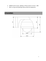
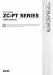
DRAWING
-6-
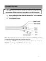
CONNECTIONS
Precautions
• The following connections should be made by qualified service
personnel or system installers in accordance with all local codes.
1、
、 Before installing please read the instructions, of the unknown,
please contact seller.
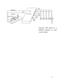
2、
、 Connections (Figure)
Note: When powered up, the dome device performs a self-check (including
one panning, tilting, zooming and focusing operation).
If control wire of RS485 connects by the connective box, it can connect as
RS485A+ with Orange wire, RS485B- with yellow wire.
-7-
Installation
1. On shield of protection, is trying to gain and installation to avoid scratches
spherical transparent and clean.
2. Choose the appropriate installation method. Speed dome camera must
be installed at the scaffold on a stable and reliable, the installation should be
in accordance with the requirements of surveillance scenes to make the
largest screen monitor, and monitor the clearest images.
3. Choose the best installation location, if possible to be able to minimize
sun, rain, avoid dust. Speed dome camera must be the work of the warming;
we should try to avoid the scorching sun exposure.
4.
Power supply should be selected with high-speed dome camera
matching power to ensure the normal operation of the speed dome camera
and long-term stability. Line voltage power supply to consider wear and tear,
a sufficient number of current job
5. Auxiliary equipment. As the project was also asked to consider
applications environmental conditions, such as at night to clear the recorded
image, then on the need to increase the environmental illumination.
6. Avoid interference. Communications and video signal cables have to be
asked to avoid electromagnetic interference, such as power transformers,
high-power electric motors or generators, high voltage generator, pulse
generator and other facilities, and these two signal lines have to wear steel
pipe laying, and strong Level voltage electric lines, with the regulatory
requirements to maintain spacing.
-8-
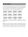
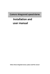
ID Code Setting
The ID code setting set by 8 digital-switch, address of speed dome camera is
from 1~255, about the Stir code of addresses 1~128, pls see the Appendix Ⅰ.
There are the parts of Stir code of addresses .Setting as below picture
(Other, please turn on and so forth in accordance with the binary):
Note: Black pane is the position of the key .Please power- off before
setting.
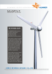
NOTE: If the Control Wire parallel connection many speed dome camera the
forest dome camera, you should connect JM1 which is in RS485 interface of
main control board .If the distance is very far ,you also should do as above
operation .Detail connect ,according to white line on the main control board.
-9-
Connect JM1 which is in
RS485 interface of main
control board.
- 10 -
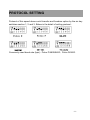
PROTOCOL SETTING
Protocol of this speed dome could transfer and freedom option by the six key
switches section 1, 2 and 3. Below is the detail of setting protocol:
Commonly used baud rate (bps):Pelco P/4800/9600;Pelco D/2400.
- 11 -
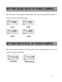
SETTING BAUD RATE OF DOME CAMERA
Set baud rate of this speed dome camera by the six key switches section 4
and 5 to select. Set as following:
SETTING PROTOCOL OF ZOOM CAMERA
Set zoom camera’s protocol of this speed dome camera by six of the last
switch. Setting as following:
- 12 -
OPERATION (Default protocol PELCO-D/2400)
The speed dome camera can be controlled remotely horizontal and vertical
movement. It is used with a system controller, separately. It is controlled
remotely from the controller through a serial connection to the RS-485
connector using a twisted-pair cable.
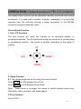
Conventional Function
1. Pan / Tilt Function
The pan function will move the camera on all horizontal planes, to
surveillance position. The tilt function will move the camera on a vertical plane,
to surveillance position. The speed is variable according to the angle of
joystick.
UP
LEFT
RIGHT
DOWN
2. Zoom Function
2.1 The filming range can be set using the zoom function.
Press TELE the LCD displays Zoom Tele
Press WIDE the LCD displays Zoom Wide
Note: When zoom in is bigger, the speed of control joystick came slow.
Otherwise, zoom out small, with faster speed.
2.2 Iris Function
Iris is AUTO。
- 13 -
3. Preset Memory
The preset memory function will memories camera positions and zoom, focus,
etc. Setting up to 128 preset camera positions can be memorized. Later, you
can easily recall any of the preset camera positions by entering its
corresponding number, and the camera will move the memorized position
with all the preset settings.
3.1 To set a preset position
SET + N + ENTER
N: the number of preset position: 1~128
3.2 To call a preset position
When camera positions have been set, you can enter a memorized camera
position number.
Preset + N + ENTER
N: the number of preset position: 1~128
4. Delete a preset position
[PRESET]+ [N] + [OFF]
N: the number of preset position: 1~128
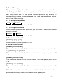
5. To call cruise tracks:
:
[PRESET]+32+[ENTER]
This command can call the No.1cruise tracks. It can scan preset points no.1 ~
16. [PRESET]+53+ [ENTER]
This command can call the No.2cruise tracks. It can scan preset points no.17
~ 31.
[PRESET]+49+ [ENTER]
This command can call the No.3cruise tracks. It can scan preset points no.33
~ 48.
[PRESET]+50+ [ENTER]
This command can call the No.4cruise tracks. It can scan preset points no.65
~ 80.
Note: If some points are not been set or delete, it will not scanning these
points when cruising. Resort 3 seconds in every preset point.
- 14 -
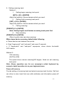
6.Setting scanning track
Method 1:
1.
Setting begin scanning track point
[SET] + [51] + [ENTER]
Adjust the position of dome camera which you need.
2.
Setting finish scanning track point:
[SET] + [52] + [ENTER]
Adjust the position of dome camera which you need.
3. Calling scanning:
[PRESET]+51+ [ENTER]
Note: Setting begins and finishes scanning track point first.
4. Stop scanning
[PRESET]+52+ [ENTER]
(Move Joystick also can stop scanning)
When dome device scanning, default state following
a. Dome device scan between two points.
b. Scan “begin-point” and “end-point” and resort 3 seconds
c. If “begin-point” and “end-point” superpose, dome device horizontal
360°rotation.
Method 2:
Call scanning
[AUTO]+ [ON]
The speed dome camera scanning360 degree. Need not set scanning
track point.
Note: Above operation use for our company’s suited keyboard by
example, detail operation do as your keyboard menu
Power-off memory
Provide setting of scanning track and select scanning track function. Self-test
can allow to store track that user edits arbitrarily and information power-off
memory.
- 15 -
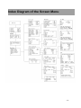
Index Diagram of the Screen Menu
- 16 -
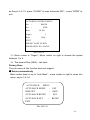
Index Diagram of the Screen Menu
This is the speed dome OSD function, which include the menu while opening
and the menu while operating.
Open it, and see the start of image, the order of showing is:
Waiting for image
Waiting…
The image of system information
Version
: 1.02
Camera
: Sony
Dome ID : 001
Protocol
: PelcoD
Band Rate : 2400
The information of checking itself
Horizontal Check OK
Vertical Check OK
Camera Check OK
The finished information of checking itself
Self test passed, you can
control the Dome Machine
now
- 17 -
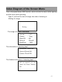
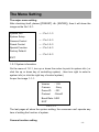
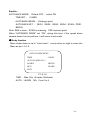
The Menu Setting
The major menu setting
After checking itself, please {[PRESET] +8+ [ENTER]}, then it will show the
image as the No.1-0-1:
System Info
→(Pic.1-1-1)
System Setup
Camera Control
→(Pic.1-2-1)
Preset Control
→(Pic.1-3-1)
Special Function
→(Pic.1-4-1)
Factory Default
→(Pic.1-5-1)
EXIT
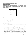
1-0-1 System information
On the menu of 1-0-1, turn up or down the rocker to point to system info ( or
click the up or down key of controlling system) , then turn right to enter to
system info( or click the right key of control system)
As per the image 1-1-1:
Version
: 1.02
Camera
: Sony
Dome ID
: 001
Protocol
: PelcoD
Baud Rate: 2400
EXIT
Pic.1-1-1
The last pages all show the system setting; the consumer can’t operate any
item of setting the function of system.
Camera function setting
- 18 -
The sub-menu of this function does not support.
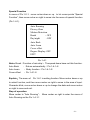
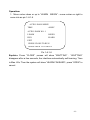
Setting Preset Position
The menu of Pic.1-0-1,move rocker down or up
to let cursor points “Preset
Control”, then move rocker on right to come into menu of setting preset
position(Pic.1-3-1):
NO. :
001
Setting
Call
Delete
EXIT
Pic.1-3-1
Explain:Above menu is used to set, call and delete preset positions.
(Pic.1-3-1):
◆
NO.: Display the No. of preset position.
◆
Setting: Setting preset position
◆
Call: Call preset position(Pic.1-3-2)
◆
Delete: Delete preset position
(No.:1-128);
Setting steps as follow:
1) In menu of Pic.1-3-1,move rocker down or up
to let cursor points
“NO.” , then move rocker on right to come into the area of input.
Character blink, move rocker down or up to change the data and move
rocker on right to save and exit. No. range is 1 to 128.
2) Move rocker down or up to let cursor points “setting”, then move
rocker on right to come into the area of setting. The screen displays the
state of setting (Pic.1-3-2).Control the dome camera by keyboard. After
setting, press “close” to save. The screen will display Pic.1-3-1, cursor
points “setting”, Setting is finish. You can call this position to confirm it is
saved
- 19 -
NO:
001
Setting
Call
Delete
EXIT
PRESS CLOSE TO SAVE
PRESS OPEN TO ESC
Pic.1-3-2
3)Select the No. of preset position before Call preset position,move rocker
down or up
to let cursor points “call”, then move rocker on right to confirm,
the camera will adjust to the preset position(Note: If the No. Of preset
position haven’t been set. Call this No., the camera will not adjust.)
4) After all setting,move rocker down or up
to let cursor points “EXIT”,
then move rocker on right to exit setting menu
- 20 -
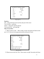
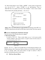
Special Function
In menu of Pic.1-0-1,move rocker down or up
to let cursor points “Special
Function”, then move rocker on right to come into the menu of special function
(Pic.1-4-1).
Auto Running
Privacy Zone
Motion Detection
Brush
: OFF
Day/night
: OFF
Auto Back
Auto Learn
Cover offset
Degree Display: OFF
EXIT
Pic.1-4-1
Note:
:Brush(Function of rain strip)
:The speed dome have not this function.
Auto Back
: Return automatically(Pic.1-4-1-4)
Auto Learn
:Study function(Pic.1-4-1-5)
Cover offset
:Pic.1-4-1-8
Explain:
:The menu of
Pic.1-4-1 is setting function. Move rocker down or up
to select function, and then move rocker on right to come in the area of input.
Character blink, move rocker down or up to change the data and move rocker
on right to save and exit.
Step of operation
Move rocker to “Auto Running”, Move rocker on right to enter the menu of
Auto Running as the Pic.1-4-1-1
- 21 -
AUTORUN CONTROL MENU
Set
:
BEGIN
Set
:
END
Run:
SCAN
Seqno:
1
Run:
SEQ
EXIT
Pic.1-4-1-1
Explain:
::
Set:setting the begin point and the end point of the track
The First Run:scanning
Seqno:setting the scanning speed
The second Run:call scanning
Step of operation:
(1)Move rocker to “Set”, Move rocker on right ,the system will show as the
pic.1-4-1-2, then set the begin point and the end point of track.
AUTORUN CONTROL MENU
SET :
SET :
RUN :
BEGIN
END
SCAN
SEGNO :
RUN
1
:
SEQ
EXIT
PRESS CLOSE TO SAVE
PRESS OPEN TO ESC
Pic.1-4-1-2
(2)Move rocker to the first “Run”, Move rocker on right ,the system will show
- 22 -
as the pic.1-4-1-3. press “CLOSE” to scan horizontal 360°;press “OPEN” to
exit.
AUTORUN CONTROL MENU
Set
:
BEGIN
Set
:
END
Run:
SCAN
Segno:
Run:
1
SEQ
EXIT
PRESS CLOSE TO RUN
PRESS OPEN TO CANCEL
Pic.1-4-1-3
(3)Move rocker to “Segno”, Move rocker on right to choose the speed
between 1 to 4.
(4)The second Run (SEQ):call track
Privacy Zone
The sub-menu of this function does not support.
◆. Return automatically
Move rocker down or up to “Auto Back”,move rocker on right to come into
menu, as pic.1-4-1-4
AUTO BACK MENU
AUTO BACK MODE :
TIME SET
:
AUTO BACK BEGIN
:
AUTO BACK SET
:
EXIT
OFF
1MIN
SET
BEGIN
Pic.1-4-1-4
- 23 -
Explain:
AUTO BACK MODE: Default OFF ,select ON
TIME SET : 0-9MIN
AUTO BACK BEGIN :Set begin point
AUTO BACK SET : SEQ1、SEQ2、SEQ3、SEQ4、SCAN、PRE1、
BEGIN
Note: SEQ is track;SCAN is scanning;PRE is preset point;
When “AUTOBACK MODE” set “ON”, during this time, if the speed dome
camera doesn’t do any actions, it will return to set mode.
◆.Study function
Move rocker down or up to “ Auto Learn”,move rocker on right to come into
Menu as pic.1-4-1-5
AUTO LEARN MENU
TIME
: 00SEC
AUTO LEARN NO: 1
LEARN
BEGIN
RUN
LEARN
EXIT
P1-4-1-5
TIME :Max. 60s. (4 tracks, 60s/track)
AUTO
LEARN
NO:From1 to 4
- 24 -
Operation:
:
1.Move rocker down or up to “LEARN
BEGIN”,move rocker on right to
come into as pic.1-4-1-6
AUTO LEARN MENU
TIME
: 00SEC
AUTO LEARN NO: 1
LEARN
BEGIN
RUN
LEARN
EXIT
PRESS CLOSE TO RUN
PRESS OPEN TO CANCEL
Pic.1-4-1-6
Explain : Press “CLOSE” ,screen will show “WAITTING” . “WAITTING”
disappear after a few seconds, the interface automatically self-learning. Time
is Max. 60s. Then the system will show “LEARN FINISHED”;press “OPEN” to
cancel.
- 25 -
2.
.Move rocker down or up to “RUN
LEARN”,move rocker on right come
into as pic.1-4-1-7 , press “CLOSE” to run self-learning, Time is
Max.60s.Then the system will show “Run finished”. If don’t move rocker,
Dome device will circularly self-learn.
Pic.1-4-1-7
AUTO LEARN MENU
TIME
: 00SEC
AUTO LEARN NO: 1
LEARN
BEGIN
RUN
LEARN
EXIT
PRESS CLOSE TO RUN
PRESS OPEN TO CANCEL
Note:
:When the dome device is in the process of learning, press SET +8 +
ENTER, dome device will exit the OSD menu and re-learn from zero second.
◆Focus on correcting the functional coverage
The sub-menu of this function does not support.
5. Recovery Function
In menu of Pic.1-0-1,Move rocker down or up
to let cursor points
“Factory Default”, then move rocker on right to come into the menu of
recovery function (Pic.1-5-1).
FACTORY
DEFAULT?
NO
YES
Pic.1-5-1
Explain:Pic.1-5-1,There is a reminder that is recovery factory setting or not.
Default setting is NO. If recovery factory setting, you can Move rocker down
or up
to choose “YES”, then move rocker on right to confirm it. After 5
seconds, automatically return main menu.
◆
Exit then Screen Menu
- 26 -
After setting, press [SET+8+ENTER] to exit the screen menu
Debugging
1.
Before the installing must be pre-set communication protocol, baud rate,
zoom camera’s protocol and ID code. A system of speed dome camera,
keyboard, and matrix must be used, such as unified communications and
unified communications protocol baud rate, and ensure that each speed
dome camera has a unique same address.
2.
Identification speed dome cameras’ power lines, communications lines
and video transmission lines, to ensure that the correct connection.
3.
Control room in the center of each speed dome camera debugging,
including: the control of the upper and lower pan/tilt reciprocating scanning
around to see if there is a halt, should not start or should not stop the
phenomenon; aperture control camera focus and zoom to see if there is
image distortion , color cast, such as Focus on the phenomenon of
non-performing; set up and call the preset point to view the accuracy of the
preset points; set up and call a variety of cruise feature to see the speed
dome camera and memory function.
4.
Preset point should not be set up at the camera straight on the location of
the sun in order to avoid damage to the camera sensor devices.
- 27 -
General Failure Analysis
(1)
After power on, no motion and no image. At this time should
check whether the normal power supply, check whether the next
anti-polarity.
(2)
Self test is exceptional, there is image but with motor noise
“wu” May inspect the installation of the camera level, the availability of
tilt, or whether the lack of power supply current.
(3)
Normal self-testing, but completely beyond the control of the
speed dome camera. Should inspect and check the communication
protocol, baud rate and ID, and to ensure that communication lines to
connect to normal. RS-485 is a polarity, that is, check the "+" and "-"
whether the anti-access.
(4)
Power on, Self testing normal, but no images, should check
video line, and if the video connections are ok.
(5)
Speed dome camera moves out of control, sometimes which
can be controlled and sometimes can not control, there can not control
the upper and lower downtime, etc. Should not influence or situation.
Such questions may be in the wiring on the quality, if the control signal
produced a distortion or signal too weak, it will lead to intelligent can not
receive the ball to the correct control commands. Control circuit wiring
irregularities such as:
(a)
Did not require the use of twisted pair, RS-485 requires the use
of twisted pair;
(b)
Wire diameter is too small resulting in weak signals. RS-485 as
- 28 -
far as the transmission distance 1200 meters, can detect a valid
signal to the minimum range 200mV, below the rate of invalid signal;
(c)
Wiring topology structure is irrational. RS-485 communication
norms require wiring type topology, and a lot of engineering to use the
star topology;
(d)
Matching resistor setting unreasonable. In order to avoid signal
lines due to impedance mismatch lead to signal reflection caused by
signal distortion must be the furthest the speed dome camera
appropriated for the use of matching resistance status;
(e)
Need avoid the laying of strong electromagnetic interference,
what is more, there is shielding layer can be twisted pair. To
determine the problem in the speed dome camera or in the wiring of a
method are: Get the questionable speed dome camera to test, if the
action of normal, then the problem lies in the quality of wiring up.
(6)
Call the track and no action. Should first check every preset
point has been set it.
(7)
Between two preset points, should not the normal scan. To
see whether or not correctly set the scan start point and end point.
(8)
Even if the rocker offset to the largest speed dome camera
action is still very slow. Some speed dome camera have the function
of low speed for far distance, that is, if the camera's zoom down the
most, up and down around the mandatory speed limit in order to
guarantee the state at low speed to see enlarged details of each
object.
- 29 -
(9)
Camera iris, focus, zoom, etc. should not work. Should check
the camera protocol on the speed dome camera.
(10) Night should not automatically switch to black and white color.
Can check the camera settings menu, the feature is set to automatic.
(11) Fuzzy screen. May be the camera is in manual status, please
set to automatically; and may also the speed dome camera’s cove
have dust and stains.
(12) Monitor images is normal, but after a Matrix character
position after the superposition wrong. May be the camera format is
not compatible with other equipment, check the camera's format,
because in general the monitor can automatically identify PAL system
and NTSC system, and other video equipment does not necessarily
have the feature.
(13) Image color cast. This is often caused by white balance
disorders, such as the integration of camera white balance SONY
have AUTO, INDOOR, OUTDOOR, ATW, such as mode, the camera
should be set to correspond with the work of the scene mode, if not
sure what kind of fit, can select AUTO or ATW.
- 30 -
Routine maintenance
Speed dome camera are compact equipment, often on their maintenance is
also necessary to avoid the question of further expansion.
(1)
Often clean the cover. At present the speed dome camera do
not have self-cleaning ability so it is necessary to periodically and
manually clean the cover.
(2)
Speed dome camera overheating, there is abnormal noises.
Confirmation are the speed dome camera at their own problems, it
should be immediately unloaded In order to avoid the speed dome
camera inside the important components such as camera further
damage.
(3)
Unless the user's special needs, it is recommended for
everyday use in the course of the speed dome camera not to always be
in high-speed automated inspection status, gear and belt to run
non-stop wear and tear, will be too fast to reduce preset point
positioning accuracy and shorten the life of the speed dome camera.
(4)
When return the bad speed dome camera to the factory. It is
suggested that tell the factory the working environment, a failure report
to the situation before and after, the manufacturers of the technical staff
will be careful analysis of the failure was accidental or there is the law
and find the best solution. This works for manufacturers and traders,
are very useful.
- 31 -
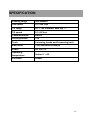
SPECIFICATION
Panning range
360°endless
Pan speed
0.1~240°/sec
Tilt range
90°(
(180°Reversal auto-flip )
Tilt speed
0.1~90°/sec
Communication
RS485
Preset position
128
Track
4 cruising tracks and 2scanning track
Baud Rate
1200/2400/4800/9600bps
Power
AC 24V 1A
Operating
temperature
S/N Ratio
Indoor 0℃~40℃
≥48dB
- 32 -
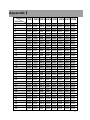
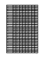
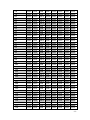
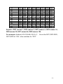
AppendixⅠ
Ⅰ
Dipswitch
Address
1
2
3
4
5
6
7
8
9
10
11
12
13
14
15
16
17
18
19
20
21
22
23
24
25
26
27
28
29
30
31
32
33
34
35
36
DIP1 DIP2 DIP3 DIP4 DIP5 DIP6 DIP7 DIP8
ON
OFF
ON
OFF
ON
OFF
ON
OFF
ON
OFF
ON
OFF
ON
OFF
ON
OFF
ON
OFF
ON
OFF
ON
OFF
ON
OFF
ON
OFF
ON
OFF
ON
OFF
ON
OFF
ON
OFF
ON
OFF
OFF
ON
ON
OFF
OFF
ON
ON
OFF
OFF
ON
ON
OFF
OFF
ON
ON
OFF
OFF
ON
ON
OFF
OFF
ON
ON
OFF
OFF
ON
ON
OFF
OFF
ON
ON
OFF
OFF
ON
ON
OFF
OFF
OFF
OFF
ON
ON
ON
ON
OFF
OFF
OFF
OFF
ON
ON
ON
ON
OFF
OFF
OFF
OFF
ON
ON
ON
ON
OFF
OFF
OFF
OFF
ON
ON
ON
ON
OFF
OFF
OFF
OFF
ON
OFF
OFF
OFF
OFF
OFF
OFF
OFF
ON
ON
ON
ON
ON
ON
ON
ON
OFF
OFF
OFF
OFF
OFF
OFF
OFF
OFF
ON
ON
ON
ON
ON
ON
ON
ON
OFF
OFF
OFF
OFF
OFF
OFF
OFF
OFF
OFF
OFF
OFF
OFF
OFF
OFF
OFF
OFF
OFF
OFF
OFF
OFF
ON
ON
ON
ON
ON
ON
ON
ON
ON
ON
ON
ON
ON
ON
ON
ON
OFF
OFF
OFF
OFF
OFF
OFF
OFF
OFF
OFF
OFF
OFF
OFF
OFF
OFF
OFF
OFF
OFF
OFF
OFF
OFF
OFF
OFF
OFF
OFF
OFF
OFF
OFF
OFF
OFF
OFF
OFF
OFF
OFF
OFF
OFF
OFF
ON
ON
ON
ON
ON
OFF
OFF
OFF
OFF
OFF
OFF
OFF
OFF
OFF
OFF
OFF
OFF
OFF
OFF
OFF
OFF
OFF
OFF
OFF
OFF
OFF
OFF
OFF
OFF
OFF
OFF
OFF
OFF
OFF
OFF
OFF
OFF
OFF
OFF
OFF
OFF
OFF
OFF
OFF
OFF
OFF
OFF
OFF
OFF
OFF
OFF
OFF
OFF
OFF
OFF
OFF
OFF
OFF
OFF
OFF
OFF
OFF
OFF
OFF
OFF
OFF
OFF
OFF
OFF
OFF
OFF
OFF
OFF
OFF
OFF
OFF
OFF
- 33 -
37
38
39
40
41
42
43
44
45
46
47
48
49
50
51
52
53
54
55
56
57
58
59
60
61
62
63
64
65
66
67
68
69
70
71
72
73
74
75
76
77
ON
OFF
ON
OFF
ON
OFF
ON
OFF
ON
OFF
ON
OFF
ON
OFF
ON
OFF
ON
OFF
ON
OFF
ON
OFF
ON
OFF
ON
OFF
ON
OFF
ON
OFF
ON
OFF
ON
OFF
ON
OFF
ON
OFF
ON
OFF
ON
OFF
ON
ON
OFF
OFF
ON
ON
OFF
OFF
ON
ON
OFF
OFF
ON
ON
OFF
OFF
ON
ON
OFF
OFF
ON
ON
OFF
OFF
ON
ON
OFF
OFF
ON
ON
OFF
OFF
ON
ON
OFF
OFF
ON
ON
OFF
OFF
ON
ON
ON
OFF
OFF
OFF
OFF
ON
ON
ON
ON
OFF
OFF
OFF
OFF
ON
ON
ON
ON
OFF
OFF
OFF
OFF
ON
ON
ON
ON
OFF
OFF
OFF
OFF
ON
ON
ON
ON
OFF
OFF
OFF
OFF
ON
ON
OFF
OFF
OFF
ON
ON
ON
ON
ON
ON
ON
ON
OFF
OFF
OFF
OFF
OFF
OFF
OFF
OFF
ON
ON
ON
ON
ON
ON
ON
ON
OFF
OFF
OFF
OFF
OFF
OFF
OFF
OFF
ON
ON
ON
ON
ON
ON
OFF
OFF
OFF
OFF
OFF
OFF
OFF
OFF
OFF
OFF
OFF
ON
ON
ON
ON
ON
ON
ON
ON
ON
ON
ON
ON
ON
ON
ON
ON
OFF
OFF
OFF
OFF
OFF
OFF
OFF
OFF
OFF
OFF
OFF
OFF
OFF
OFF
ON
ON
ON
ON
ON
ON
ON
ON
ON
ON
ON
ON
ON
ON
ON
ON
ON
ON
ON
ON
ON
ON
ON
ON
ON
ON
ON
OFF
OFF
OFF
OFF
OFF
OFF
OFF
OFF
OFF
OFF
OFF
OFF
OFF
OFF
OFF
OFF
OFF
OFF
OFF
OFF
OFF
OFF
OFF
OFF
OFF
OFF
OFF
OFF
OFF
OFF
OFF
OFF
OFF
OFF
OFF
OFF
OFF
OFF
OFF
OFF
OFF
ON
ON
ON
ON
ON
ON
ON
ON
ON
ON
ON
ON
ON
ON
OFF
OFF
OFF
OFF
OFF
OFF
OFF
OFF
OFF
OFF
OFF
OFF
OFF
OFF
OFF
OFF
OFF
OFF
OFF
OFF
OFF
OFF
OFF
OFF
OFF
OFF
OFF
OFF
OFF
OFF
OFF
OFF
OFF
OFF
OFF
OFF
OFF
OFF
OFF
OFF
OFF
- 34 -
78
79
80
81
82
83
84
85
86
87
88
89
90
91
92
93
94
95
96
97
98
99
100
101
102
103
104
105
106
107
108
109
110
111
112
113
114
115
116
117
118
OFF
ON
OFF
ON
OFF
ON
OFF
ON
OFF
ON
OFF
ON
OFF
ON
OFF
ON
OFF
ON
OFF
ON
OFF
ON
OFF
ON
OFF
ON
OFF
ON
OFF
ON
OFF
ON
OFF
ON
OFF
ON
OFF
ON
OFF
ON
OFF
ON
ON
OFF
OFF
ON
ON
OFF
OFF
ON
ON
OFF
OFF
ON
ON
OFF
OFF
ON
ON
OFF
OFF
ON
ON
OFF
OFF
ON
ON
OFF
OFF
ON
ON
OFF
OFF
ON
ON
OFF
OFF
ON
ON
OFF
OFF
ON
ON
ON
OFF
OFF
OFF
OFF
ON
ON
ON
ON
OFF
OFF
OFF
OFF
ON
ON
ON
ON
OFF
OFF
OFF
OFF
ON
ON
ON
ON
OFF
OFF
OFF
OFF
ON
ON
ON
ON
OFF
OFF
OFF
OFF
ON
ON
ON
ON
ON
OFF
OFF
OFF
OFF
OFF
OFF
OFF
OFF
ON
ON
ON
ON
ON
ON
ON
ON
OFF
OFF
OFF
OFF
OFF
OFF
OFF
OFF
ON
ON
ON
ON
ON
ON
ON
ON
OFF
OFF
OFF
OFF
OFF
OFF
OFF
OFF
OFF
ON
ON
ON
ON
ON
ON
ON
ON
ON
ON
ON
ON
ON
ON
ON
ON
OFF
OFF
OFF
OFF
OFF
OFF
OFF
OFF
OFF
OFF
OFF
OFF
OFF
OFF
OFF
OFF
ON
ON
ON
ON
ON
ON
ON
OFF
OFF
OFF
OFF
OFF
OFF
OFF
OFF
OFF
OFF
OFF
OFF
OFF
OFF
OFF
OFF
OFF
OFF
ON
ON
ON
ON
ON
ON
ON
ON
ON
ON
ON
ON
ON
ON
ON
ON
ON
ON
ON
ON
ON
ON
ON
ON
ON
ON
ON
ON
ON
ON
ON
ON
ON
ON
ON
ON
ON
ON
ON
ON
ON
ON
ON
ON
ON
ON
ON
ON
ON
ON
ON
ON
ON
ON
ON
ON
ON
ON
ON
ON
ON
ON
ON
ON
OFF
OFF
OFF
OFF
OFF
OFF
OFF
OFF
OFF
OFF
OFF
OFF
OFF
OFF
OFF
OFF
OFF
OFF
OFF
OFF
OFF
OFF
OFF
OFF
OFF
OFF
OFF
OFF
OFF
OFF
OFF
OFF
OFF
OFF
OFF
OFF
OFF
OFF
OFF
OFF
OFF
- 35 -
119
120
121
122
123
124
125
126
127
128
255
ON
OFF
ON
OFF
ON
OFF
ON
OFF
ON
OFF
ON
ON
OFF
OFF
ON
ON
OFF
OFF
ON
ON
OFF
ON
OFF
OFF
OFF
OFF
ON
ON
ON
ON
OFF
OFF
ON
ON
ON
ON
ON
ON
ON
ON
OFF
ON
ON
ON
ON
ON
ON
ON
ON
ON
OFF
ON
ON
ON
ON
ON
ON
ON
ON
ON
OFF
ON
ON
ON
ON
ON
ON
ON
ON
ON
OFF
OFF
OFF
OFF
OFF
OFF
OFF
OFF
OFF
OFF
ON
ON
ON
ON
ON
ON
ON
ON
Explain:
:DIP1 means 1, DIP2 means 2, DIP3 means 4, DIP5 means 16,
DIP6 means 32, DIP7 means 64, DIP8 means 128;
For example: Address 241=128+64+32+16+1, So set the DIP1,DIP5 DIP6,
DIP7,DIP8 for “ON”, other switches for “OFF”
- 36 -