1
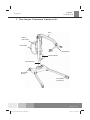
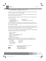
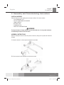
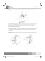
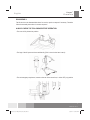
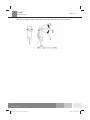
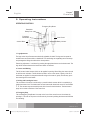
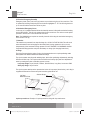
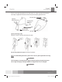
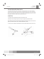
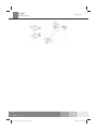
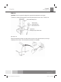
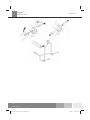
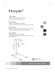
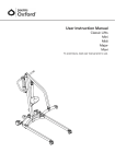
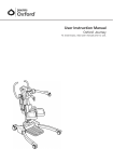
Hoyer ® Hoyer Presence User Instruction Manual & Warranty ® To avoid injury, read user manual prior to use. Hoyer Presence Manuel de l’utilisateur et garantie ® Afin d’éviter tout accident, veuillez lire attentivement la notice avant utilisation. Hoyer Presence Manual de Instrucciones y Garantia para el Usuario ® Para evitar posibles daños, lea previamente el manual de usuario. Hoyer Presence Benutzerhandbuch und Garantie ® Um Verletzungen zu vermeiden, lesen Sie bitte die Gebrauchsanweisung vor der ersten Benutzung. Redefining patient handling 294000.10061 Hoyer Presence (A5).indd 1 7/8/2011 10:14:17 AM ® Hoyer Presence English Manufacturer’s Contact Details ® Hoyer USA Joerns Healthcare Inc. 2100 Design Road Suite 100, Arlington TX 76014, USA Tel: 800-826-0270 Fax: 800-457-8827 www.joerns.com Contents 1. 2. 3. 4. 5. 6. 7. 8. 9. 10. The Hoyer Presence Patient Lift .................................................................... Introduction: About Your Lift ........................................................................... Assembly and Commissioning Instructions .................................................... Safety Precautions ......................................................................................... Operating Instructions .................................................................................... Removal of Spreader Bar/Cradle Systems .................................................... Charging Instructions...................................................................................... Maintenance Schedule & Daily Check List .................................................... Technical Specifications ................................................................................. Warranty ......................................................................................................... 3 4 5 9 11 15 17 19 21 23 2 294000.10061 Rev. A 294000.10061 Hoyer Presence (A5).indd 2 7/8/2011 10:14:17 AM ® Hoyer Presence English 1. The Hoyer Presence Patient Lift Boom Battery/ Control Pack Push Handle Spreader Bar Electric Actuator Mast Extrusion Rear Castor (braked) Front Castor (non-braked) 3 294000.10061 Rev. A 294000.10061 Hoyer Presence (A5).indd 3 7/8/2011 10:14:17 AM ® Hoyer Presence English 2. Introduction: About Your Lift The Hoyer Presence is an electrically operated patient lift. Each Presence lift is fully assembled load tested and certified before being packed/shipped. The packing consists of a strong, purpose built carton that is used for both export and domestic markets to ensure the safe arrival of the lift. A number of documents are supplied in a wallet, and packed with each lift and should be kept safely for future reference. • TEST • USER • DEALER CERTIFICATE GUARANTEE CARD • PACKING CHECK LIST • CUSTOMER MANUAL SATISFACTION CARD The TEST CERTIFICATE is an important document and will be required for your insurance records. It is valid for six months and after it has expired the lift should be inspected and serviced per the maintenance schedule. Servicing and periodic testing can be carried out by your authorized supplier. Please ensure your lift is included in their maintenance schedule. If you are at all unsure what your local market servicing requirements are, please check with your dealer and/or a local government agency. The Hoyer Presence is suitable for the following CATEGORIES of lift within the working parameters of the lifts specified in the TECHNICAL SPECIFICATIONS. Category A - Wheelchair Category B - Bed Category C - Bath (dependent upon setting) Category D - Toilet/Shower Chair Category E - Floor Category F - 90 degree Rotation The Hoyer Presence is suitable for patients in the SITTING, SITTING/RECUMBENT and RECUMBENT positions. The examples of slings suitable for this device are listed as follows • Hoyer Quickfit • Hoyer Full Back • Hoyer Quickfit Deluxe • Hoyer Long Seat The CE mark: • Hoyer Access • Hoyer Comfort • Hoyer Silkfit The Hoyer Presence carries the CE mark and complies with the following EC directives: • Medical Device Directive (93/42/EEC) • EMC Directive (89/336/EEC) • Low Voltage Directive (73/23/EEC) 4 294000.10061 Rev. A 294000.10061 Hoyer Presence (A5).indd 4 7/8/2011 10:14:18 AM ® Hoyer Presence English 3. Assembly and Commissioning Instructions CARTON CONTENTS Place the carton in a clear working area and open carefully. The carton contains: • Hoyer PRESENCE LIFT • WALLET CONTAINING DOCUMENTS • HAND CONTROL • BATTERY PACK • CHARGING LEAD • DESK TOP CHARGER/STAND WARNING The Hoyer Presence is heavy and will need to be lifted with care. You may need assistance to lift the Hoyer Presence from the carton. ASSEMBLY INSTRUCTIONS Remove all the parts from the carton and place on the floor, taking care to protect the finish from damage. 1. Place the chassis in a clear space and apply the rear bakes. 2. Fit the mast and boom assembly into the chassis socket 5 294000.10061 Rev. A 294000.10061 Hoyer Presence (A5).indd 5 7/8/2011 10:14:18 AM ® Hoyer Presence English 3. Tighten the mast assembly with the mast-locking device, which is located at the front of the chassis. WARNING Avoid trapping fingers. Keep fingers away from the end of the mast when inserting into the chassis socket. Full engagement of the mast is indicated by the label on the side of the mast. The electric leg operation will not function unless the mast is fully engaged. 4. Turn the locking knob until hand tight. 5. Line the handle assembly up to the rear of the mast, and attach using the fixings provided. The fixings and wrench needed to attached the handle are kept in the user instruction wallet for safe keeping. NOTE: When attaching the handle to the mast be sure that all trailing wires are left outside the handle before fixing. 6. Fit power pack to the lift and make sure the latch holding the pack in place is fully engaged. “Click” in place. 6 294000.10061 Rev. A 294000.10061 Hoyer Presence (A5).indd 6 7/8/2011 10:14:18 AM ® English Hoyer Presence DISASSEMBLY The lift should not be disassembled unless for service, repair or transport if necessary. Therefore follow the assembly instructions in reverse sequence. ALWAYS CHECK THE FOLLOWING BEFORE OPERATION • The mast is fully locked into position. • The legs of the lift open and close satisfactorily (This is done via the hand control). • The red emergency stop button, located on the rear of the control box, is in the OFF (out) position. 7 294000.10061 Rev. A 294000.10061 Hoyer Presence (A5).indd 7 7/8/2011 10:14:18 AM ® Hoyer Presence English • Push the up and down buttons on the hand control and confirm the boom rises and lowers. 8 294000.10061 Rev. A 294000.10061 Hoyer Presence (A5).indd 8 7/8/2011 10:14:19 AM ® Hoyer Presence English 4. Safety Precautions Please read and follow the safety precautions listed below. The operation and use of Hoyer patient lifts is simple and straightforward. Following these few basic safety precautions will make lifting operations easy and trouble free. READ AND UNDERSTAND THE USER INSTRUCTION MANUAL BEFORE USING YOUR “PRESENCE” WARNING • ALWAYS plan your lifting operations before commencing. • ALWAYS carry out the DAILY CHECK LIST before using the lift. • ALWAYS familiarise yourself with the operating control and safety features of a lift before lifting a patient. • DO NOT use a sling unless it is recommended for use with the lift. • ALWAYS check the sling is suitable for the particular patient and is of the correct size and capacity. • NEVER use a sling which is frayed or damaged. • ALWAYS fit the sling according to the instructions provided (user instructions). • ALWAYS check the safe working load of the lift is suitable for the weight of the patient. • ALWAYS carry out lifting operations according to the instructions in the user manual. • NEVER disconnect or bypass a control or safety feature because it seems easier to operate the lift. • DO NOT lift a patient with the castor brakes on. Always let the lift find the correct center of gravity. • DO NOT attempt to manoeuvre the lift by pushing on the mast, boom or patient. • ALWAYS manoeuvre the lift with the handle / foot push pad provided. • ALWAYS lower the patient to the lowest comfortable position before transfers. • DO NOT push a loaded lift at speeds which exceed a slow walking pace (3 Km/hour 0.8 metres/second). • DO NOT push the lift over uneven or rough ground. Particularly if loaded. • DO NOT attempt to push/pull a loaded lift over a floor obstruction. • NEVER force an operating/safety control. All controls are easy to use and do not require excessive force. 9 294000.10061 Rev. A 294000.10061 Hoyer Presence (A5).indd 9 7/8/2011 10:14:19 AM ® Hoyer Presence English • The MINIMUM load required to manually lower the hoist using the mechanical emergency down function is 30 kg. • DO NOT park a loaded lift on ANY sloping surface. • DO NOT use electric lifts in a shower. • DO NOT charge an electric lift in a bathroom or shower room. • DO NOT lift a patient unless you are trained and competent to do so. • YOUR lift is for patient lifting. DO NOT use it, or allow it to be used, for any other purpose. • DO NOT bump the lift down steps, loaded or unloaded. • DO NOT attempt to negotiate a loaded lift on a slope which exceeds 1:12 (approximately 5 degrees). • DO NOT attempt to negotiate a slope without a second helper being present. • DO NOT use in a wet or corrosive environment such as poolside locations. • Joerns Healthcare recommends that slings be checked regularly and particularly before use for signs of fraying or damage. DO NOT use slings that are worn or damaged. • HOYER RECOMMENDS THE USE OF GENUINE HOYER PARTS. Hoyer slings and lifters are not designed to be interchangeable with other manufacturer’s products. Using other manufacturer’s products on Hoyer products is potentially unsafe and could result in serious injury to patient and/or caregiver. • Refer to maximum weight capacity of lift. Sling capacity is limited by the maximum capacity of the lift. 10 294000.10061 Rev. A 294000.10061 Hoyer Presence (A5).indd 10 7/8/2011 10:14:19 AM ® Hoyer Presence English 5. Operating Instructions OPERATING CONTROLS Emergency Stop Button Detachable Battery Pack Emergency Lower/Raise Actuator Motor Hand Control Battery Indicator 1. Leg adjustment The legs on the Hoyer Presence are electrically adjustable for width. The legs can be opened to enable access around armchairs or wheelchairs. For transferring and negotiating narrow doorways and passages the lift legs should be in the closed position. Electric leg adjustment - is achieved by pressing the appropriate buttons on the handcontrol. The legs will be locked whenever the handcontrol switch is released. 2. Castors and Braking The lift has two braked castors which can be applied for parking. When lifting, the castors should be left free and un-braked. The lift will then be able to move to the center of gravity of the lift. If the brakes are applied it is the patient that will swing to the center of gravity and this may prove disconcerting and uncomfortable. 3. Raising and lowering the boom The movement of the boom is achieved by a powerful electric actuator which is controlled by a simple handcontrol unit. The handcontrol has two buttons with directional arrows UP and DOWN . The actuator stops automatically at the limit of travel in both directions. The handcontrol plugs into a socket at the base of the control box. 4. Emergency Stop The red Emergency Stop Button is located on the front of the control box and is activated by pressing in. This will cut all power to the lift and only be reset by twisting the button anticlockwise and releasing. 11 294000.10061 Rev. A 294000.10061 Hoyer Presence (A5).indd 11 7/8/2011 10:14:19 AM ® Hoyer Presence English 5. Electrical Emergency Down/Up Emergency lower (down) and raise (up) buttons are provided at the front of the control box. This is operated by inserting a ballpoint pen into the button highlighted . This will bring the boom up or down should the handcontrol fail at any time. 6. Mechanical Emergency Down In the case of a complete electrical failure the electrical actuator is fitted with mechanical lowering device (RED BOSS). This will only operate when the lift is under load. The device must be pulled upwards to activate, and a slow decent will commence. Note: The MINIMUM load required to manually lower the hoist using the mechanical emergency down function is 30 kg. 7. Batteries The batteries are protected from deep discharge by a LOW VOLTAGE ALARM. This will sound when the batteries need recharging and the handcontrol is being operated. It will not sound independently of the handcontrol being operated. DO NOT IGNORE THIS WARNING ALARM. Complete the lifting operation and place the battery on charge (see charging instructions). 8. Slings The Hoyer Presence has the option of both a 6-point spreader bar and a 4-point positioning cradle. Both systems use different attachment methods and slings. The 6-point system uses slings with webbing loops, which allow positioning adjustment by selecting different coloured loops. The 4-point cradle uses the Secruri3 safety clip system and adjustment is made by rotating the 4-point cradle either upward or down. Loop strap slings: Hoyer Quickfit, Full Back, Quickfit Deluxe, Long Seat, Access and Silkfit Safety clip slings: Hoyer Comfort The 6-point system attaches to the spreader bar hooks via loop straps (shown below), each sling is supplied with instructions. Please study the instruction guide before use. Leg Strap Attachment Points Shoulder Straps Shoulder Strap Attachment Points Leg Straps 6-point spreader bar. Example of 6-point spreader bar sling with loop attachments. 12 294000.10061 Rev. A 294000.10061 Hoyer Presence (A5).indd 12 7/8/2011 10:14:19 AM ® Hoyer Presence English The four point cradle sling attaches to the cradle studs via a safety clip system (shown below), each sling is supplied with instructions. Please study the instruction guide before use Shoulder Straps Leg Strap Attachment Points Shoulder Strap Attachment Point Shoulder Strap Attachment Point Leg Straps 4-point positioning cradle. Example of 4-point cradle sling with safety clip system. Securi3 sling attachment system. Example of installation. NOTE: For detailed fitting instructions, please refer to the user guide supplied with each sling. WARNING Joerns Healthcare recommends that slings be checked regularly and particularly before use for signs of fraying or damage. DO NOT use slings that are worn or damaged. WARNING 13 294000.10061 Rev. A 294000.10061 Hoyer Presence (A5).indd 13 7/8/2011 10:14:19 AM ® Hoyer Presence English HOYER RECOMMENDS THE USE OF GENUINE HOYER PARTS. Hoyer slings and lifters are not designed to be interchangeable with other manufacturer’s products. Using other manufacturer’s products on Hoyer products is potentially unsafe and could result in serious injury to patient and/or caregiver. WARNING Refer to maximum weight capacity of lift. Sling capacity is limited by the maximum capacity of the lift. 6. Removal of Spreader Bar/Cradle Systems 14 294000.10061 Rev. A 294000.10061 Hoyer Presence (A5).indd 14 7/8/2011 10:14:19 AM ® English Hoyer Presence FOLLOW THESE INSTRUCTIONS EXACTLY Your presence lift has the option of using both a 6-point spreader bar and 4-point positioning cradle. The removal of either of these systems is completed easily by the use of a quick-release pin. This is done quickly and easily, but you must read the following safety instructions to ensure the spreader bar/cradle is safely locked into position before use. CONNECTION To connect, raise the spreader bar/cradle up toward the boom slot. Insert the pin sleeve through the plastic end cap and to support the spreader bar/cradle. Once aligned in the boom slot reinsert the quick release pin fully into the sleeve until it locks into position. YOU MUST CHECK THAT THE PIN IS SECURELY FITTED. To do this, press your finger into the barbed end. If the pin remains stationary the lift is safe to use. 15 294000.10061 Rev. A 294000.10061 Hoyer Presence (A5).indd 15 7/8/2011 10:14:19 AM ® Hoyer Presence English 16 294000.10061 Rev. A 294000.10061 Hoyer Presence (A5).indd 16 7/8/2011 10:14:19 AM ® Hoyer Presence English REMOVAL CAUTION: Be sure to support the weight of the spreader bar/cradle before removing pin. To detach pin, depress the spring barb (using a flat blade electrical screw driver or similar) and Removable Battery Pack Hand Control Legs Open/Close, Boom Raise/Lower Control Box Emergency Stop, Raise/Lower pull the pin out. Support the spreader bar/cradle, and then pull the pin sleeve in the opposite direction, removing it completely from the boom. This will release the spreader bar completely. 17 294000.10061 Rev. A 294000.10061 Hoyer Presence (A5).indd 17 7/8/2011 10:14:19 AM ® Hoyer Presence English 18 294000.10061 Rev. A 294000.10061 Hoyer Presence (A5).indd 18 7/8/2011 10:14:20 AM ® English Hoyer Presence 7. Charging Instructions The batteries are located in the power pack and are charged via an off board desktop charger unit. When the battery pack needs charging it is removed from the lift and fitted to an off board charging unit. 1. Remove the power pack from the lift. The pack is retained by a simple latch at the top of the power pack. Lift the latch and the power pack will be released. 2. Fit the power pack to the charging unit. The location and latching of the power pack to the charger is the same system as used on the lift. 3. Plug the charger mains plug into a suitable mains outlet. 4. Charging is automatic and will fully charge the batteries over a period of eight to twelve hours. Note: Even if the charger is left plugged in for extended periods it will not allow the batteries to overcharge. a) Green Light - Indicates main power is on. b) Yellow Light - Indicates battery is charging. c) Battery will be fully charged when yellow light goes off. Note: Charging will take up to 4 hours. It is recommended that the battery be charged immediately up on receipt. 5. To return the lift to service, disconnect power supply remove the power pack from the charger. Fit the power pack to the lift and make sure the latch holding the pack in place is fully engaged. “Click” in place. The charging of Hoyer electric lifts is simple and straightfor ward, but it is important to follow the charging instructions closely. Please pay particular attention to the following warnings, they will help you avoid problems with discharged batteries. 19 294000.10061 Rev. A 294000.10061 Hoyer Presence (A5).indd 19 7/8/2011 10:14:20 AM ® Hoyer Presence English 1. SPREADER BAR: Check the spreader bar for freedom of rotation and swing. Check for wear on the central pivot. Check for firm attachment to the boom. 2. BOOM: Check the attachment of the boom to the mast. Make sure there is only minimal side movement of the boom and the boom is free to rotate on the boom bearing. 3. MAST: Check the operation of the mast-locking device. Make sure the mast fully engages into the socket. Check the bottom actuator. 4. ACTUATOR: The actuator should require no maintenance other than checking for correct operation and listening for unusual noise. 5. POWER PACK: Check the function of the emergency stop button and emergency down/up. Note: The MINIMUM load required to manually lower the hoist using the emergency lower function is 30 kg. 6. BATTERIES: The batteries are housed in the power pack and should not require maintenance other than the regular charging as detailed in the charging instructions. Check that the connections remain clean. 7. LEG ADJUSTMENT: Check the legs operate in both full extensions (inward/outward). 8. CASTORS: Check all castors for firm attachment to the legs. Check for free rotation of the castor and the wheels. 9. CLEANING: Clean with ordinary soap and water and/or any hard surface disinfectant. Harsh chemical cleaners or abrasives should be avoided as these may damage the surface finish of the lift. Avoid wetting any of the electrical parts. 10. LOAD TEST: The load test should be carried out in accordance with the manufacturer’s test procedures. It is strongly recommended the testing is carried out by an authorized service dealer. 11. BASE AND WHEELS: Ensure base is even and level (all four wheels are on the floor). 12. SLINGS: Check for wear and fraying. 13. LUBRICATION: Oil pivot joints, including mast and boom connections, pedal assembly, spreader bar joint (only if required). 14. HAND SET: Ensure plugged fully into controller. 15. QUICK RELEASE PIN: Ensure the pin is securely fitted before lifting, by pressing the barbed end. 16. FIXINGS: Check all nuts, bolts, screws and fasteners for excessive wear and for tightness. Replace as required. Service Intervals * Before Use X = Recommended = Required * 6 months in North America Initially *THESE CHECKS SHOULD INCLUDE: X X X 20 294000.10061 Rev. A 294000.10061 Hoyer Presence (A5).indd 20 7/8/2011 10:14:20 AM ® Hoyer Presence English WARNING KEEP the batteries fully charged. Place the battery on charge whenever it is not in use. If it is more convenient to do so, place on charge every night. The charger will not allow the batteries to overcharge. WARNING NEVER run the batteries completely flat. As soon as the audible warning sounds, complete the lifting operation in hand and place on charge. CAUTION NEVER store the power pack for long periods without regular charging throughout the storage period. WARNING ALWAYS make sure the mains power to the charger is switched off before connecting or disconnecting the power pack. WARNING NEVER leave the power pack plugged in to the charger with the mains power off. WARNING Do not charge an electric lift in a bathroom or shower room. 21 294000.10061 Rev. A 294000.10061 Hoyer Presence (A5).indd 21 7/8/2011 10:14:20 AM ® Hoyer Presence English 8. Maintenance Schedule & Daily Check List All Hoyer products are designed for minimum maintenance, however some safety checks and procedures are required. A schedule of DAILY tasks are detailed below. Daily checks and a six monthly service, inspection and test will ensure a lift is kept in optimum safe working condition. A list of spare parts is available upon request. The LOAD TEST and certification should only be carried out by qualified personnel or an authorized service agent / dealer. DAILY CHECK LIST: Joerns Healthcare strongly recommends the following checks be carried out on a daily basis and before using lift. • • • • • • • • MAKE sure the lift moves freely on its castors. MAKE sure the spreader bar is free to rotate and swing EXAMINE the spreader bar is firmly attached to the boom. EXAMINE the sling hooks/clips on the spreader bar and side suspenders for excessive wear. MAKE sure the legs open and close correctly. OPERATE the hand control to confirm the boom raises and lowers satisfactorily. ON electric powered lifts check the operation of the emergency stop button. EXAMINE slings for fraying or other damage. DO NOT use any sling if damaged or if the sling shows signs of wear. • CONFIRM the lift is not giving a low battery alarm when the hand control is operated. If the alarm sounds, DO NOT use, and place on charge immediately. MAINTENANCE, INSPECTION AND TEST Joerns Healthcare recommend a thorough inspection and test of the Hoyer Presence lift and lifting accessories, slings, scales etc is carried out on a regular basis. Inspection frequency varies depending on locality, so you must check with your dealer or local government agency as appropriate regarding how often an inspection is required. The examination and test should be conducted according to the recommendations and procedures provided in this manual. Joerns Healthcare recommends maintenance, inspection and certified testing is carried out by authorized service agent / dealers only. 22 294000.10061 Rev. A 294000.10061 Hoyer Presence (A5).indd 22 7/8/2011 10:14:20 AM ® Hoyer Presence English 9. Technical Specifications Safe Working Load .........................................................500 lbs 227 kgs Maximum Overall Length ................................................57.5 inches 1460 mm Minimum Overall Length .................................................55.1 inches 1400 mm Maximum Overall Height .................................................81.3 inches 2065 mm Minimum Overall Height ..................................................57.5 inches 1460mm Spreader Bar Maximum Height ......................................75.2 inches 1910 mm Spreader Bar Minimum Height ........................................16.9 inches 430 mm Height at Maximum Reach ..............................................51.5 inches 1310 mm Reach at Maximum Height ..............................................25.6 inches 650 mm Reach at Minimum Height ...............................................15.7 inches 400 mm Maximum Reach* ............................................................36.6 inches 930 mm Turning Radius ................................................................64.2 inches 1630 mm Legs Open- External Width ............................................45.2 inches 1150 mm Legs Open- Internal Width ..............................................40.1 inches 1020 mm Legs Closed- External Width ..........................................26.4 inches 670 mm Legs Closed- Internal Width ...........................................21.6 inches 550 mm Overall Height of Legs.....................................................4.7 inches 120 mm Ground Clearance ...........................................................1.4 inches 35 mm Front Twin Castors ..........................................................4 inches 100 mm Rear Braked Castors .......................................................4 inches 100 mm * Reach = center of spreader bar to the front of the mast 4-point Position Cradle (measurement to top of location pins) Cradle Max. Height..........................................................61 inches 1550 mm Cradle Min. Height (usable) ............................................15.4 inches 390 mm Weights Mast, Base & Boom Assembly ........................................81.4 lbs (includes 2 point spreader bar) 37 kgs Power Pack .....................................................................6.6 lbs 3 kgs Total.................................................................................88 lbs 40 kgs Base Assembly (not inc battery) .....................................44 lbs 20 kgs 23 294000.10061 Rev. A 294000.10061 Hoyer Presence (A5).indd 23 7/8/2011 10:14:20 AM Joerns Healthcare Inc. 2100 Design Road Suite 100, Arlington TX 76014 USA Tel: 800-826-0270 Fax: 800-457-8827 www.joerns.com © 2011, Joerns Healthcare 294000.10061 Rev A DCO. 11-0339 294000.10061 Hoyer Presence (A5).indd 92 7/8/2011 10:14:25 AM