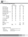
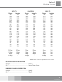
1
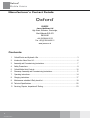
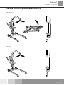
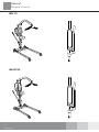
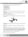
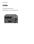
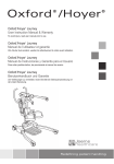
Oxford
®
Oxford Mobile Hoists
User Instruction Manual & Warranty
®
To avoid injury, read user manual prior to use.
Redefining patient handling
Oxford
Mobile Hoists
®
Manufacturer’s Contact Details
Oxford
®
EuropE
Joerns Healthcare Ltd
High Street, Wollaston, Stourbridge,
West Midlands DY8 4PS
ENGLAND
+44 (0)1384 44 66 22
Fax: +44 (0)1384 44 66 01
www.joerns.co.uk
Contents
1. Oxford Electric and Hydraulic Lifts......................................................................................... 3
2. Introduction: About Your Lift................................................................................................... 6
3. Assembly and Commissioning Instructions............................................................................ 7
4. Safety Precautions................................................................................................................. 9
5. Oxford Mobile Hoist Controls............................................................................................... 10
6. Stowaway: Assembly and Commissioning Instructions.........................................................11
7. Operating instructions.......................................................................................................... 14
8. Charging instructions............................................................................................................ 17
9. Maintenance schedule & Daily check list............................................................................. 18
10. Technical Specifications....................................................................................................... 20
11. Servicing, Repairs, Inspections & Testing............................................................................ 23
374-10070 Rev A
Oxford
Mobile Hoists
®
Oxford Electric and Hydraulic Lifts
STOWAWAY:
MINI 140:
374-10070 Rev A
Oxford
Mobile Hoists
®
Midi 170
Major 190
374-10070 Rev A
Oxford
Mobile Hoists
®
Maxi 170
374-10070 Rev A
Oxford
Mobile Hoists
®
2. Introduction: About Your Lift
The Oxford Mobile Hoists are available in two versions, hydraulically operated and electrically operated.
This manual covers both versions. (This is with the exception of the Maxi 170 which is electric only).
Each lift is fully assembled, load tested and certified before being partially dismantled for packing. The
packing consists of a strong, purpose built carton and is used for both export and domestic markets to
ensure the safe arrival of the lift.
A number of documents are supplied in a wallet packed with each lift and should be kept safely for
future reference.
•
•
•
•
Test Certificate
User Manual
Dealer Guarantee Card
Customer Satisfaction Card
The TEST CERTIFICATE is an important document and will be required for your insurance records. It
is valid for six months and after it has expired the lift should be inspected and serviced for the following
six months. Servicing and periodic testing can be carried out by your supplier. Please ensure your lift is
included in their maintenance schedule.
Oxford Mobile Hoists are suitable for the following CATEGORIES of lift within the working parameters of
the lifts specified in the TECHNICAL SPECIFICATIONS.
•
•
•
•
•
•
Category A - Wheelchair
Category B - Bed
Category C - Bath
Category D - Toilet/Shower Chair
Category E - Floor
Category F - 90 degree Rotation
The Oxford Mobile Hoists are suitable for patients in the SITTING, SITTING/RECUMBENT and
RECUMBENT positions.
The CE mark:
374-10070 Rev A
Oxford Mobile Hoists carries the CE mark and complies with the following
EC directives:
• Medical Device Directive (93/42/EEC)
• EMC Directive (89/336/EEC) (Electrics only)
• Low Voltage Directive (73/23/EEC) (Electrics only)
Oxford
Mobile Hoists
®
3. Assembly and Commissioning Instructions
Place the carton in a clear working area and open carefully. The carton contains:
•
•
•
•
•
•
•
Main Wheeled Chassis
Mast and Boom Assembly
Leg Adjusting Handle
Wallet Containing Documents
Handcontol (electric only)
Battery Charger (electric only)
Battery Pack
1. Remove all the parts from the carton and place on the floor, taking care to protect the finish from
damage.
SAFETY NOTE: Some of the parts are heavy and will need to be lifted with care. You may need
assistance with the heavier assemblies.
2. Apply the brakes on the rear castors of the chassis.
3. Fit the mast assembly to the chassis. The mast is located into the rectangular socket on the top centre of
the chassis.
SAFETY NOTE: Avoid trapping fingers. Keep fingers away from the end of the mast when inserting
into the socket.
4. When the mast is fully engaged with the socket, turn the mast locking knob clockwise until fully
tightened.
SAFETY NOTE: Full engagement of the mast is indicated by the label on the side of the mast.
5. Remove the screw from the leg adjusting lever located at the rear of the chassis. Fit the leg adjusting
handle through the gate on the mast and push the open end over the leg adjusting lever. Align the
notch in the handle with the cross pin in the lever. The handle is retained by a screw through the
clearance hole in the handle into a threaded hole in the lever. Insert screw and fully tighten.
NOTE: For Stowaway please refer to page 11 for assembly instructions.
6. Check the legs of the lift open and close satisfactorily.
374-10070 Rev A
Oxford
Mobile Hoists
®
Electric Model:
7. Check the red emergency stop button, located on the Controller is in the out (off position).
8. Fit the handcontrol to the handcontrol socket located at the base of the Controller.
WARNING
The handcontrol plug is indexed and can only be fitted one way. Do not force, but make sure
the plug of the handcontrol is firmly pushed into the socket.
9. Plug the actuator jack plug into the (left socket) actuator socket located at the base of the
Controller.
10.Push the up and down buttons on the handcontrol and confirm the boom rises and lowers. The lift is now ready for use.
Hydraulic Model:
7. Close the hydraulic unit release valve by turning the knurled black knob on the unit fully clockwise.
NOTE: The release valve requires only minimal tightening to operate and should only be closed
finger tight. DO NOT apply excessive force to the valve knob as this will result in damage to the
valve.
8. Pump the handle of the hydraulic unit and confirm the ram raises the boom.
9. Open the release valve fully anticlockwise and check the boom descends. An
unloaded boom will not come down under its own weight, it will be necessary to apply some pressure to the boom before it will descend.
WARNING
The release valve is fully open and encounters a positive end stop in less than two full turns of
the knob. DO NOT force the valve past the end stop as this will result in damage to the valve.
10. Close the release valve. The lift is now ready for use.
374-10070 Rev A
Oxford
Mobile Hoists
®
4. Safety Precautions
Please read and follow the safety precautions listed below. The operation and use of Oxford patient lifts
is simple and straightforward. Following these few basic safety precautions will make lifting operations
easy and trouble free.
WARNING
• ALWAYS plan your lifting operations before commencing.
• ALWAYS carry out the DAILY CHECK LIST before using the lift.
• ALWAYS familiarise yourself with the operating control and safety features of a lift before lifting a patient.
•DO NOT use a sling unless it is recommended for use with the lift.
• ALWAYS check the sling is suitable for the particular patient and is of the correct size and capacity.
• NEVER use a sling which is frayed or damaged.
• ALWAYS fit the sling according to the instructions provided (user instructions).
• ALWAYS check the safe working load of the lift is suitable for the weight of the patient.
• ALWAYS carry out lifting according to the instructions in the user manual.
• NEVER disconnect or bypass a control or safety feature because it seems easier to operate the lift.
• NEVER force an operating or safety control. All controls are easy to use and do not require excessive force to operate. If a control is not working easily there will be a reason. Forcing will only strain or damage the lift and may compromise safety.
•DO NOT lift a patient with the castor brakes on.
•DO NOT attempt to manoeuvre the lift by pushing on the mast, boom or patient.
• ALWAYS manoeuvre the lift with the handle provided.
• ALWAYS lower the patient to the lowest comfortable position before transfers.
•DO NOT push a loaded lift at speeds which exceed a slow walking pace
(3 Kilometres/hour 0.8 metres/second).
•DO NOT push the lift over uneven or rough ground. particularly if loaded.
•DO NOT attempt to push or pull a loaded lift over a floor obstruction which the castors are unable to ride over easily.
•DO NOT bump the lift down steps, loaded or unloaded.
•DO NOT attempt to negotiate a loaded lift on a slope which exceeds 1:12 (approximately 5 degrees). Joerns Healthcare recommend a second helper is present when moving a patient on a slope.
•DO NOT park a loaded lift on ANY sloping surface.
•DO NOT use electric lifts in a shower.
•DO NOT charge an electric lift in a bathroom or shower room.
•DO NOT lift a patient unless you are trained and competent to do so.
• YOUR lift is for patient lifting. DO NOT use it, or allow it to be used, for any other purpose.
374-10070 Rev A
Oxford
Mobile Hoists
®
5. Oxford Mobile Hoist Controls
Detachable
Battery Pack
Emergency
Stop Button
Emergency
Raise/Lower
Actuator
Motor
Hand
Control
Battery
Indicator
10
374-10070 Rev A
Oxford
Mobile Hoists
®
6. Stowaway: Assembly & Commissioning
Instructions
1. Remove all the parts from the carton and place on the floor, taking care to protect the finish from
damage.
WARNING
The Stowaway is heavy and will need to be lifted with care. You may need assistance to lift
the Stowaway from the carton.
2. Place the folded Stowaway flat on the floor, resting on the rear castors and the folded boom.
Engage the brakes on the rear castors.
3. Stand facing the front castors and swing the leg retaining latches clear of the square handle on the
mast. Move the legs sideways and downwards to place the front castors on the floor.
11
374-10070 Rev A
Oxford
Mobile Hoists
®
4. Swing the mast and boom upright and allow the mast to drop into the mast box.
WARNING
Avoid trapping fingers. Keep fingers away from the end of the mast when inserting into the
socket. Engage the mast lock.
5. Remove the quick release pin at the top of the actuator, this will release both the boom and the
actuator. Hydraulic version - The hydraulic unit is completely detached when the Stowaway is
folded. Remove the quick release pin to release the boom and use the pin to reconnect the top of
the hydraulic unit to the boom. Connect the lower mounting of the hydraulic unit to the mast with the
second quick release pin stored through the mast bracket.
6. Lift the boom and spreader bar and swing the actuator over to engage with the mounting bracket on the
underside of the boom. Secure the actuator to the boom mounting bracket with the quick release pin.
WARNING
Make sure the quick release pin is correctly located and locked.
12
374-10070 Rev A
Oxford
Mobile Hoists
®
Hand control
Retaining
Clips
Emergency
Raise/Lower
Leg Adjusting
Handle
Leg Adjusting
Handle
Emergency
Stop
7. Remove leg adjusting handle from the storage clips on the mast and fit to the leg adjusting lever
through the gate on the mast. Fit the battery pack to the mounting point on the mast and connect
the power/charging plug to the battery pack.
WARNING
The handcontrol plug is indexed and can only be fitted one way. Do not force, but make sure the
plug of the handcontrol is firmly pushed into the socket.
Plug the actuator jack plug into the (left socket) actuator socket located at the base of the Controller.
Check the following:
• The legs of the lift open and close satisfactorily.
• The red emergency stop button, located on the top of the power pack, is in the OFF (out) position.
• Push the up and down buttons on the handcontrol and confirm the boom rises and lowers.
13
374-10070 Rev A
Oxford
Mobile Hoists
®
7. Operating Instructions
1. Leg adjustment: The legs on the Mobile Hoists are adjustable for width. The legs can be opened
to enable access around armchairs or wheelchairs. For transferring and negotiating narrow doorways and passages the lift legs should be in the closed position. To achieve the adjustment, the leg
adjuster handle, located at the rear of the mast, is moved in towards the mast and then sideways from
RIGHT (fully closed) to LEFT (fully open). The adjustment can be carried out with the patient in the lift,
but loaded or unloaded the adjustment should be made when the lift is moving.
2. Castors and Braking: The lift has two braked castors which can be applied for parking. When lifting, the
castors should be left free and unbraked. The lift will then be able to move to the centre of gravity
of the lift. If the brakes are applied it is the patient that will swing to the centre of gravity and this
may prove disconcerting and uncomfortable.
3. Straight line steering (where supplied): One of the rear castors is fitted with a straight line steering
device. To engage the device simply swing the ‘U’ shaped bar over the end of the leg. There is no
need to fit the bar over the castor as it will automatically engage as you move off.
4. Raising and lowering the boom (electric models): The movement of the boom is achieved by a
powerful electric actuator which is controlled by a simple handcontrol unit. The handcontrol has two
buttons with directional arrows UP and DOWN. The actuator stops automatically at the limit of travel
in both directions. The handcontrol plugs into a socket at the base of the Controller. There is a magnetic
backing to the handcontrol which allows it to be “parked” on the mast or boom when not in use.
5. Emergency Stop (Electric only): The red Emergency Stop Button is located on the Controller and
is activated by pressing in. This will cut all power to the lift and can only be reset by twisting the
button anticlockwise and releasing.
6. Emergency Raise/Lower Function: All Oxford Mobile Hoists are fitted with raise/lower buttons on
the Controller. These are located underneath the emergency stop button and can be operated by
means of inserting a ball point pen tip. This can be used to lower/raise the patient should the hand
control fail. Caution should be exercised when using this control as there is no automatic cut-out of
the actuator when the top or bottom stop is reached.
7. Emergency Mechanical Lower: Some hoists have the additional feature of a mechanical emergency
lower fitted to the actuator. This is identified by a red moulded block at the base of the actuator ram.
By pulling on the device upwards the boom will be lowered in a controlled manner. This feature
is only to be used when the there is no electrical power to the actuator and the patient needs
to be lowered immediately. Before using this feature the electrical lower function should be
used check that the emergency stop has not been pressed in and that the battery has adequate
charge This feature requires a sufficient downward load to be applied to the boom to work.
There may be circumstances where the carer or operator of the hoist will require applying an
additional downward force on the boom to enable the boom to be lowered.
WARNING
Care must be taken to avoid personal injury when applying any additional downward force to
the boom in order to activate the emergency descent.
14
374-10070 Rev A
Oxford
Mobile Hoists
®
WARNING
Frequent, repetitive use of the emergency descent feature may result in future safety issues
with the emergency descent function.
If the emergency descent device is used then you are required to contact your service provider to
check the hoist to establish what needs replacing or repairing.
WARNING
Continued use of the hoist after using the emergency descent feature may compromise the duty
of care and safety of the patient.
8. Batteries: The batteries are protected from deep discharge by a LOW VOLTAGE ALARM. This will
sound when the batteries need recharging and the handcontrol is being operated. It will not sound
independently of the handcontrol being operated. DO NOT IGNORE THIS WARNING ALARM.
Complete the lifting operation and place the lift on charge (see charging instructions).
9. Raising and lowering the boom (hydraulic models): The raising and lowering of the boom is
achieved by a powerful hydraulic ram which is operated by two simple controls. The release valve,
which is identified by a black knurled knob, and the pump handle which is a long lever on the side
of the hydraulic unit.
To raise the boom, ensure the release valve is closed. The valve is closed by gently turning the
knurled knob fully clockwise. When closed, pump the long handle with smooth even strokes for
maximum effect. The handle strokes from an upright position through an arc of 90 degrees. Leave
the handle in the upright position when not in use.
WARNING
DO NOT force the handle beyond the upper or lower stops. The hydraulic unit can be rotated
to allow the handle to be used from either side of the lift.
To lower the boom, turn the release valve anticlockwise. The release valve is progressive, the more it
is opened the faster the descent. The valve is restricted so even when fully open the descent is
controlled. This facility allows for a “hands free” descent.
If the release valve is opened a fraction (a quarter turn) a very slow speed of descent will allow the
carer to work “hands free” while assisting or comforting the patient.
REMEMBER to close the release valve before commencing lifting operations. The release valve
only requires gentle pressure to open or close.
WARNING
DO NOT apply excessive force to the release valve, either to close or to open. It is not necessary and will only damage the valve.
15
374-10070 Rev A
Oxford
Mobile Hoists
®
10.Slings: The selected sling is attached to the spreader bar hooks. Each sling is supplied with
instructions which should be followed carefully.
The Oxford mobile hoist range is suitable for patients in the SITTING, SITTING/RECUMBENT and RECUMBENT positions. The slings suitable for this device are listed as follows:
• Oxford Quickfit sling
• Oxford Quickfit Deluxe sling
• Oxford Access sling
• Oxford Full Back sling
• Oxford Long seat sling
• Oxford Silkfit sling
When selecting a sling from the Oxford range be sure to assess the suitability of the type of sling for the patient to be lifted. The following guides will assist in the correct selection.
NOTE: For detailed fitting instructions, please refer to the user guide supplied with each sling.
WARNING
Joerns Healthcare recommends that slings be checked regularly and particularly before use for
signs of fraying or damage. DO NOT use slings that are worn or damaged.
WARNING
OXFORD RECOMMENDS THE USE OF GENUINE OXFORD PARTS. Oxford sling and lift products
are designed to be compatible with one another. For country specific guidance on sling use and
compatibility, please refer to the sling label or contact your local market distributor or Joerns
Healthcare.
WARNING
Refer to maximum weight capacity of lift. Sling capacity is limited by the maximum capacity of
the lift.
8. Charging Instructions
The batteries are located in the power pack and are charged through two contacts on the base. When
16
374-10070 Rev A
Oxford
Mobile Hoists
®
the power pack needs charging it is removed from the lift and fitted to a charging unit. Joerns Healthcare
recommend an additional power pack is purchased, so that one pack can be on charge at all times.
1. Remove the power pack from the lift. The pack is retained by a simple latch at the top of the pack.
Lift the latch and the power pack will be released.
2. Fit the power pack to the charging unit. The location and latching of the power pack to the charger
is the same system as used on the lift.
3. Plug the charger mains plug into a suitable mains outlet and switch the mains supply ON.
4. Charging is automatic and will fully charge the batteries over a period of eight to twelve hours.
Note: Even if the charger is left plugged in for extended periods it will not allow the batteries to
“overcharge”.
5. To return the lift to service, switch OFF the mains supply and remove the power pack from the
charger. Fit the power pack to the lift and make sure the latch holding the pack in place is fully
engaged.
The charging of Oxford electric lifts is simple and straightforward, but it is important to follow the
charging instructions closely. Please pay particular attention to the following points, they will help
you avoid problems with discharged batteries.
WARNING
• KEEP the batteries fully charged. Place the power pack on charge whenever it is not in use.
If it is more convenient to do so, place on charge every night. The charger will not allow
the batteries to “overcharge”.
• NEVER run the batteries completely flat. As soon as the audible warning sounds, complete the lifting operation in hand and place on charge.
• NEVER store the power pack for long periods without regular charging throughout the storage period.
• ALWAYS make sure the mains power to the charger is switched off before connecting or disconnecting the power pack.
• NEVER leave the power pack plugged in to the charger with the mains power off.
• ALWAYS check Battery Charge Indicator (LCD) screen.
• Batteries NOT to be opened by unauthorised personnel. (Contact your distributor for warranty and reapirs).
•DO NOT touch battery/charger terminals.
•DO NOT leave charger switched on with battery disconnected.
17
374-10070 Rev A
Oxford
Mobile Hoists
®
9. Maintenance Schedule and Daily Check List
All Oxford products are designed for Minimum maintenance, however some safety checks and
procedures are required. A schedule of DAILY tasks are detailed below.
Daily checks and a biannual service, inspection and test will ensure a lift is kept in optimum safe working
condition. A list of spare parts is available upon request. The LOAD TEST and CERTIFICATION should
only be carried out by qualified personnel or an authorised service dealer.
DAILY CHECK LIST
Joerns Healthcare Ltd strongly recommend the following checks are carried out on a daily basis and
before using the lift.
• MAKE sure the lift moves freely on it’s castors.
• MAKE sure the spreader bar is free to rotate and swing. Check the spreader bar is firmly attached
to the boom.
• EXAMINE the sling hooks on the spreader bar and side suspenders for excessive wear.
If in doubt - do not use.
• MAKE sure the sling retaining disks on the spreader bar are fitted and function as intended.
• MAKE sure the legs open and close correctly.
• OPERATE the handcontrol or the hydraulic unit to confirm the boom raises and lowers satisfactorily.
• CONFIRM the lift is not giving a low battery alarm when the handcontrol is operated (electric lifts
only). If the alarm sounds DO NOT use and place on charge immediately.
• ON electric powered lifts check the operation of the emergency stop button.
• ON hydraulically operated lifts check for hydraulic fluid leakage. Any leakage should be reported to a
service engineer immediately and the lift should not be used until it has been checked out.
• ON lifts with detachable masts make sure the mast is fully engaged and the locking knob is fully
tightened.
• EXAMINE slings for fraying or other damage. DO NOT use any sling if damaged or if the sling
shows signs of wear.
MAINTENANCE, INSPECTION AND TEST
Joerns Healthcare Ltd recommend a thorough inspection and test of the Oxford Mobile Hoist lifting
accessories, slings etc. is carried out every six months. The examination and test should be conducted
according to the recommendations and procedures below. Joerns Healthcare recommend maintenance,
inspection and certified testing is carried out by authorised service dealers only.
Note: These recommendations are in compliance with the requirements of 1998 No2307 Health and
Safety: The Lifting Operations and Lifting Equipment Regulations 1998. This is a UK regulation. Outside
the UK please check your local requirements.
18
374-10070 Rev A
Oxford
Mobile Hoists
®
• SPREADER BAR: Check the spreader bar for freedom of rotation and swing. Check for wear on the
central pivot. Check for firm attachment to the boom. Inspect for excessive wear on the sling hooks
and any side suspenders used in conjunction with the spreader bar. Check that the sling retaining
disks are fitted and function as intended
• BOOM: Check the attachment of the boom to the mast. Make sure there is only minimal side
movement of the boom and the boom is free to rotate on the boom bearing. Check the actuator or
hydraulic unit mounting on the boom.
• MAST: Check the operation of the mast locking device. Make sure the mast fully engages into the
socket. Check the bottom actuator or hydraulic unit mounting.
• POWER PACK (Electric only): Check the function of the Emergency Stop button. Inspect the hand
control socket for correct fitting. Inspect the power/charging socket for correct fitting. Check functioning
of hand control.
• LEG ADJUSTMENT: Check the leg linkages are secure and the leg adjustment handle is located
correctly in the leg adjustment gate. Operate the leg adjusting handle and confirm smooth opening
and closing of the legs. Adjust linkages if necessary.
• LEG PIVOTS: Check the leg pivots are secure and the legs pivot freely. Any stiffness must be
investigated. Strip out the leg pivots and lubricate with a light mineral based grease if in any doubt.
Make sure there is no excessive play in the leg pivots.
• CASTORS: Check all castors for firm attachment to the legs. Check for free rotation of the castor and
the wheels. Remove any build up of threads, hair or fluff. Lubricate if necessary with a light mineral
based grease. Check correct operation of the brakes.
• ACTUATOR (Electric only): The actuator should require no maintenance other than checking for
correct operation and listening for unusual noise.
• EMERGENCY RAISE /LOWER AND EMERGENCY DESCENT: Check both the electrical
Emergency Raise/Lower and the Emergency Descent function using the maximum safe working
load applied to the end of the boom. Please note that the practice of using a spring balance will not
correctly check the function of the emergency descent function.
• HYDRAULIC UNIT: The hydraulic unit should require no maintenance other than checking for correct
operation and leakage of hydraulic fluid.
• BATTERIES (Electric only): The batteries are located in the Power Pack and should not require
maintenance other than the regular charging as detailed in the charging instructions.
• CLEANING: Clean with ordinary soap and water and/or any hard surface disinfectant. Harsh chemical
cleaners or abrasives should be avoided as these may damage the surface finish of the lift. Avoid
wetting any of the electrical parts.
• SLINGS: Check for wear and fraying.
• LOAD TEST: The load test should be carried out in accordance with the manufacturers test procedures. It
is strongly recommended the testing is carried out by an authorised service dealer.
• CERTIFICATION: An authorised service dealer will issue a test certificate after satisfactory completion
of the load test. This certificate will be valid for six months.
19
374-10070 Rev A
Oxford
Mobile Hoists
®
10. Technical Specifications
STOWAWAY 140
MINI 140
Safe Working Load
Maximum Overall Length Minimum Overall Length
Maximum Overall Height
Minimum Overall Height
Spreader Bar Max. Height
Spreader Bar Min. Height
Spreader Bar Height at Maximum Reach
Reach at Maximum Height
Reach at Minimum Height
Maximum Reach
Turning Radius1104
Legs Open - External Width
- Internal Width
Legs Closed - External Width
- Internal Width Overall Height of Legs
Ground Clearance
Front Twin Castors
Rear Braked Castors
Electric
140
1093
1093
1780
1145
1572
500
995
340
505
635
1104
1095
1040
600
540
140
25
100
110
Hydraulic
140
1093
1093
1780
1145
1572
500
995
340
505
635
1104
1095
1040
600
540
140
25
100
110
Electric
140
1120
1120
1726
1133
1505
500
986
340
475
595
1104
1095
1040
600
540
100
25
100
110
Hydraulic
140
1120
1120
1726
1133
1505
500
986
340
475
595
Weights:
Mast & Boom Inc. all fixings
Base Assembly
Assembled Unit
Battery
-
-
28kgs
3.375kgs
-
-
28kgs
-
17.5kgs
11kgs
28.5kgs
3.375kgs
17.5kgs
11kgs
28.5kgs
-
ELECTRICAL SPECIFICATIONS
•
•
•
•
Batteries:
Battery Capacity:
Charger Rated Input:
Charger Rated Output:
20
374-10070 Rev A
2 X 12 volt Rechargeable sealed lead acid type
3.2 Ampere hours
100-240V AC/24 VDC 50/60 Hz. Max 400MA
29.5 VDC. Max 19W
1095
1040
600
540
100
25
100
110
Oxford
Mobile Hoists
®
MIDI 170MAJOR 190MAXI 170
Electric
Hydraulic
Electric
Hydraulic
Electric
170
170
190
190
170
1180
1180
1269
1269
1315
1180
1180
1269
1269
1315
1848
1848
1941
1941
2117
1237
1237
1376
1376
1560
1630
1630
1725
1725
1965
495
495
525
525
755
1070
1070
1110
1110
1351
412
412
589
589
512
480
480
522
522
533
656
656
754
754
724
1174
1174
1274
1274
1273
1175
1175
1160
1160
1140
1120
1120
1130
1130
1130
600
600
610
610
610
540
540
540
540
540
100
100
100
100
100
25
25
15
15
15
100
100
100
100
100
110
110
159
159
159
20.5kgs
11.5kgs
32kgs
3.375kgs
20.5kgs
11.5kgs
32kgs
-
23kgs
19kgs
42kgs
3.375kgs
23kgs
19kgs
42kgs
-
24kgs
19kgs
43kgs
3.375kgs
Hydraulic
N/A
N/A
N/A
N/A
N/A
N/A
N/A
N/A
N/A
N/A
N/A
N/A
N/A
N/A
N/A
N/A
N/A
N/A
N/A
N/A
N/A
N/A
N/A
N/A
NOTE: Reach = Centre of spreader bar to front of mast
ELECTRIC SHOCK PROTECTION
Charger...............................................................Class II
Lift......................................................................Internal Power Source
DEGREE OF SHOCK PROTECTION
Charger...............................................................Type B
Lift......................................................................Type B
21
374-10070 Rev A
Oxford
Mobile Hoists
®
Environmental Conditions:
Outside this environment functionality and safety may be compromised.
Operating:
Temperature . ........................................................5°C to 40°C
Relative humidity....................................................20% to 90% @ 30°C - not condensing
Atmospheric pressure............................................700 to 1060 hPa
Storage:
Temperature ..........................................................-10°C to +50°C
Relative humidity....................................................20% to 90% @ 30°C - not condensing
Atmospheric pressure............................................700 to 1060 hPa
IP RATINGS
Control Box ...........................................................IP43
Actuator..................................................................IP54
Off Board Charger . ...............................................IP65
Battery ...................................................................IP65
Handset .................................................................IP65
DUTY CYCLES
Actuator..................................................................10% (2 min./18 min.)
Charger .................................................................Approx. 4 hrs.
KEY SYMBOLS:
The following symbols are used on the charger, control unit and battery:
Type B equipment, as per EN 60601-1
Class 2 equipment
The disposal of the charging and control unit should not be mixed with general household waste
The disposal of batteries should not be mixed with general household waste.
For indoor use
ATTENTION, consult accompanying documents.
22
374-10070 Rev A
Oxford
Mobile Hoists
®
11. Servicing, Repairs, Inspections and Testing
Joerns Healthcare Ltd has an established network of reputable distributors and dealers who will be
pleased to handle all your purchasing, warranty, repair and maintenance enquires.
Included with each lift is a prepaid Customer Satisfaction card. Please take the time to fill it in and return
it to Joerns Healthcare Ltd. Our products are guaranteed for a period of twelve months from the date of
manufacture or twelve months from the date of purchase if commissioned by an authorised dealer. We
recommend that all of our products are commissioned by your dealer and are supported by them for
future servicing.
The dealer or distributor operates the warranty programme, so it is important to keep a record of their name
address and telephone number so they can be contacted should any problem arise.
If you are in doubt where your lift was purchased, Joerns Healthcare Ltd can trace the supplier if you quote
the serial number of the lift.
REMEMBER: Contact your distributor for purchases, Warranty, repairs, servicing and annual
certified maintenance.
Your distributor:
23
374-10070 Rev A
Joerns Healthcare Ltd
High Street, Wollaston
Stourbridge, West Midlands
DY8 4PS
ENGLAND
Tel: +44 (0)1384 44 66 22
Fax: +44 (0)1384 44 66 01
www.joerns.co.uk
© 2009, Joerns Healthcare
374-10070 Rev A