1
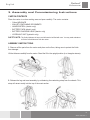
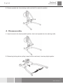
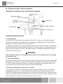
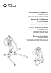
Oxford® Advance English Manufacturer’s Contact Details Oxford ® EUROPE Joerns Healthcare Limited Drakes Broughton Business Park, Worcester Road Drakes Broughton, Pershore, Worcestershire WR10 2AG United Kingdom Tel: 0844 811 1156 • Fax: 0844 811 1157 [email protected] • www.joerns.co.uk Contents 1. 2. 3. 4. 5. 6. 7. 8. 9. 2 294000.10003 Rev. C Oxford Advance Patient Lift............................................................................ Introduction: The Oxford Advance Patient Lift ............................................... Assembly and Commissioning Instructions .................................................... Disassembly ................................................................................................... Safety Precautions ......................................................................................... Operating Instructions .................................................................................... Maintenance Schedule ................................................................................... Technical Specifications ................................................................................. Warranty ......................................................................................................... 3 4 5 7 10 12 16 18 20 Oxford® Advance English 1. The Oxford Advance Patient Lift OXFORD ADVANCE LIFT (READY FOR USE) Leg Restraining Cord Boom Battery/ Control Pack Push Handle Cradle/Spreader Bar Electric Actuator Push Pad Spreader Bar Retaining Cradle Mast Tightening Knob Base Casting Leg Extrusion Braked Caster OXFORD ADVANCE LIFT (STORAGE POSITION) 3 294000.10003 Rev. C Oxford® Advance English 2. Introduction: The Oxford Advance Patient Lift ABOUT YOUR LIFT Statement of Intended Use: The intended use of the lifting device is to transfer an individual from one resting surface to another (such as a bed to a wheelchair). Moving a person in a sling over ANY distance is not recommended. The Oxford Advance is available in two versions, hydraulically operated and electrically operated. This manual covers both Advance models. Each lift is fully assembled, load tested and certified before being packed/shipped. The packing consists of a strong, purpose built carton and is used for both export and domestic markets to ensure the safe arrival of the lift. A number of documents are supplied in a wallet packed with each lift and should be kept safely for future reference. • TEST CERTIFICATE GUARANTEE CARD • DEALER • USER MANUAL SATISFACTION CARD • CUSTOMER The TEST CERTIFICATE is an important document and should be kept for reference purposes. To properly maintain your lift please refer to the maintenance schedule included in this document. If you are at all unsure what your country’s servicing requirements are, please check with your dealer and/or a local government agency. The Oxford Advance is suitable for the following CATEGORIES of lift within the working parameters of the lifts specified in the TECHNICAL SPECIFICATIONS. Category A - Wheelchair Category B - Bed Category C - Bath (dependent upon setting) Category D - Toilet/Shower Chair Category E - Floor Category F - 90 degree Rotation The Oxford Advance is suitable for patients in the SITTING, SITTING/RECUMBENT and RECUMBENT positions. The examples of slings suitable for use with this device are listed as follows: • Oxford Quickfit • Oxford Full Back • Oxford Quickfit Deluxe The CE mark: 4 294000.10003 Rev. C • Oxford Long Seat • Oxford Access sling • Oxford Silkfit The Oxford Advance carries the CE mark and complies with the following EC directives: • Medical Device Directive (93/42/EEC) • EMC Directive (89/336/EEC) (Electrics only) • Low Voltage Directive (73/23/EEC) (Electrics only) Oxford® Advance English 3. Assembly and Commissioning Instructions CARTON CONTENTS Place the carton in a clear working area and open carefully. The carton contains: • Oxford ADVANCE • WALLET CONTAINING DOCUMENTS • HANDCONTROL (electric only) • BATTERY PACK (electric only) • BATTERY CHARGING LEAD (electric only) • HYDRAULIC UNIT (hydraulic only) SAFETY NOTE: The Oxford Advance is heavy and will need to be lifted with care. You may need assistance to lift the Oxford Advance from the carton. ASSEMBLY INSTRUCTIONS 1. Remove all the parts from the carton and place on the floor, taking care to protect the finish from damage. Lift the Advance carefully from the carton. Stand the lift in the upright position (in a triangular stance). 2. Release the leg and mast assembly by unfastening the restraining strap from the wheels. This strap will retract neatly into the top of the mast section. 5 294000.10003 Rev. C Oxford® Advance English 3. Lay the Advance flat on the floor (ensure rear castors are securely locked). 4. Lift the mast assembly upright (using the top of the push handle), and drop the mast into the slot (1), tighten mast lock knobs (2), release braked castors (3). SAFETY NOTE: Avoid trapping fingers. Keep fingers away from the end of the mast when inserting into the mast slot. Tighten the mast-locking device, and unlock the braked castors at the rear. 5. Open legs fully. ENSURE leg-locking knob inserts flush against the base casting and the legs will no longer move freely. The legs will then only operate by the use of the foot pedal mechanism located at the rear of the base. 6 294000.10003 Rev. C English Oxford® Advance 6. Release spreader bar from retaining cradle, and the lift is ready for operation. 4. Disassembly 1. Lower the mast to the lowest possible position, then insert spreader bar into retaining cradle. 2. Release leg-locking device (pulling it away from the cast base), close legs tightly together. 7 294000.10003 Rev. C Oxford® Advance English 3. Loosen mast locking device (2 - not fully) lift the mast and boom assembly (3), and fold carefully toward the legs. Use the push handle to assist this motion. NOTE: If you wish to separate the mast and boom completely from the base and legs, undo the mast locking device fully (remove) and lift the mast and boom completely free from the base. Be careful not to loose the mast lock device’s, knob and location spindle. 4. Lift the folded Advance upright (using the legs and push handle as a guide) being careful that the mast and boom stay together as you tilt upright. 8 294000.10003 Rev. C Oxford® Advance English 5. Pull the restraining strap sharply upwards and extend over the wheels. (This will keep the legs, mast and boom neatly together during transit and storage). NOTE: Care should be exercised when folding/unfolding an Advance as there is a possible danger of pinching the fingers etc. Please follow the instructions carefully and ask for assistance if you are unsure of the correct procedure. ALWAYS CHECK THE FOLLOWING BEFORE OPERATION • The legs are fully engaged from the stowed position (see assembly instructions, step 5) • The mast is fully locked into position (see assembly instructions, step 4) • The legs of the lift open and close satisfactorily. • The red emergency stop button, located on the rear of the control box, is in the OFF (out) position. • Push the up and down buttons on the hand control and confirm the boom rises and lowers. • Fit the power pack to the lift and make sure the latch holding the pack in place is fully engaged. “Click” in place. HYDRAULIC MODELS ONLY Close the hydraulic unit release valve by turning the knob clockwise on the unit. NOTE: The release valve requires only minimal tightening to operate and should only be closed finger tight • DO NOT apply excessive force to the valve knob as this will result in damage to the valve. • • Pump the handle of the hydraulic unit and confirm the ram raises the boom. Open the release valve fully anticlockwise and check the boom descends. An unloaded boo will not come down under its own weight. It may be necessary to apply some pressure to the boom before it will descend. NOTE: The release valve is fully open and encounters a positive end stop in less than two full turns of the knob. WARNING When lowering a patient, open the valve very slowly. Rapidly opening the valve may cause the boom to lower quickly which may cause injury to the patient. 9 294000.10003 Rev. C Oxford® Advance English 5. Safety Precautions Please read and follow the safety precautions listed below. The operation and use of Oxford patient lifts is simple and straightforward. Following these few basic safety precautions will make lifting operations easy and trouble free. READ AND UNDERSTAND THE USER INSTRUCTION MANUAL BEFORE USING YOUR “ADVANCE” LIFT WARNING: Important safety information for hazards that might cause serious injury. CAUTION: Information for preventing damage to the product. NOTE: Information to which you should pay special attention. WARNING • ALWAYS plan your lifting operations before commencing. • ALWAYS carry out the DAILY CHECK LIST (page 16) before using the lift. • ALWAYS familiarise yourself with the operating control and safety features of a lift before lifting a patient. • DO NOT use a sling unless it is recommended for use with the lift. • ALWAYS check the sling is suitable for the particular patient and is of the correct size and capacity. • NEVER use a sling, which is frayed or damaged. • ALWAYS fit the sling according to the instructions provided (user instructions). • ALWAYS check the safe working load of the lift is suitable for the weight of the patient. • ALWAYS carry out lifting operations according to the instructions in the user manual. • NEVER disconnect or bypass a control or safety feature because it seems easier to operate the lift. • DO NOT lift a patient with the castor brakes on. Always let the lift find the correct centre of gravity. • DO NOT attempt to maneuver the lift by pushing on the mast, boom or patient. • ALWAYS maneuver the lift with the handle provided. • ALWAYS lower the patient to the lowest comfortable position before transfers. • DO NOT push a loaded lift at speeds, which exceed a slow walking pace (3 Kilometers/hour 0.8 meters/second). • DO NOT push the lift over uneven or rough ground. Particularly if loaded. 10 294000.10003 Rev. C English Oxford® Advance • DO NOT attempt to push/pull a loaded lift over a floor obstruction, which the castors are unable to ride over. • NEVER force an operating/safety control. All controls are easy to use and do not require excessive force. • The MINIMUM load required to manually lower the hoist using the mechanical emergency down function is 30 kg. • DO NOT park a loaded lift on ANY sloping surface. • DO NOT use electric lifts in a shower. • DO NOT charge an electric lift in a bathroom or shower room. • DO NOT lift a patient unless you are trained and competent to do so. • YOUR lift is for patient lifting. DO NOT use it, or allow it to be used, for any other purpose. • DO NOT bump the lift down steps, loaded or unloaded. • DO NOT attempt to negotiate a loaded lift on a slope, which exceeds 1:12 (approximately 5 degrees). • DO NOT attempt to negotiate a slope without a second helper being present. • ALWAYS check the hoist is not charging before moving as the electrical connection may be damaged. 11 294000.10003 Rev. C Oxford® Advance English 6. Operating Instructions OPERATING CONTROLS FOR THE OXFORD ADVANCE Detachable Battery Pack Emergency Stop Button Emergency Lower/Raise Hand Control Battery Indicator Actuator Motor Charger Point OPERATING INSTRUCTIONS 1. Leg adjustment The legs on the Oxford Advance are adjustable for width. The legs can be opened to enable access around armchairs or wheelchairs. For transferring and negotiating narrow doorways and passages the lift legs should be in the closed position. To achieve the adjustment, the leg adjuster pedal, located at the rear of the base, is compressed right (DOWN) to open the legs outwards and left (UP) to close the legs. The adjustment can be carried out with the patient in the lift, but whether loaded or unloaded the adjustment should be made when the lift is moving. WARNING Never lift with the legs in the closed/transport position. The closed position is for storage and transport only. 2. Castors and Braking The lift has two braked castors, which can be applied for parking. When lifting, the castors should be left free and un-braked, so that the lift will then be able to move to the centre of gravity of the lift. DO NOT apply the brakes because if the brakes are applied the patient might swing to the centre of gravity and this may prove disconcerting and uncomfortable. 3. Raising and lowering the boom (electric models) The movement of the boom is achieved by a powerful electric actuator, which is controlled by a simple hand control unit. The hand control has two buttons with directional arrows UP and DOWN. The actuator stops automatically at the limit of travel in both directions. The hand control plugs into a socket at the base of the control box. There is a hook on the rear of the hand control, which allows it to be “parked” on the mast or boom when not in use. 12 294000.10003 Rev. C Oxford® Advance English 4. Emergency Stop (Electric only) The red Emergency Stop Button is located on the rear of the control box and is activated by pressing in. This will cut all power to the lift and only be reset by twisting the button counterclockwise and releasing. 5. Emergency Lower/Raise Emergency lower/raise buttons are provided at the rear of the control box. This is operated by inserting the tip of a ball point pen into the button highlighted “lower/raise”. This will bring the boom down/up should the hand control fail at any time. 6. Mechanical Emergency Down (Electrical Down) In the case of a complete electrical failure the electric actuator is fitted with mechanical lowering device (RED BOSS). This will only operate when the lift is under load. The device must be pulled upwards to activate and a slow decent will commence. Note: The MINIMUM load required to manually lower the hoist using the mechanical emergency down function is 30 kg. 7. Batteries The batteries are protected from deep discharge by a LOW VOLTAGE ALARM. This will sound when the batteries need recharging and the hand control is being operated. It will not sound independently of the hand control being operated. CAUTION: DO NOT IGNORE THIS WARNING ALARM. Complete the lifting operation and place the lift on charge (see charging instructions). 8. Raising and lowering the boom (hydraulic models) WARNING Never loosen or unscrew the retaining bolt of the hydraulic jack unless you are an authorised competent engineer. Never load whilst user needs to rotate hydraulic jack. If the user intends to rotate the jack strongly, it may impact the patient or cause unforseen danger to patient and/or caregiver. The raising and lowering of the boom is achieved by a powerful hydraulic ram, which is operated by two simple controls. The release valve, which is identified by a silver star shaped knob, and the pump handle which is a long lever on the side of the hydraulic unit to raise the boom. The valve is closed by gently turning the knob fully clockwise. When closed, pump the long handle with smooth even strokes for maximum effect. The handle strokes from an upright position through an arc of 90 degrees. Leave the handle in the upright position when not in use. DO NOT force the handle beyond the upper or lower stops. The hydraulic unit can be rotated to allow the handle to be used from either side of the lift. To lower the boom, turn the release valve anticlockwise. The release valve is progressive, the more it is opened the faster the descent. The valve is restricted so even when fully open the descent is controlled. This facility allows for a “hands free” descent. If the release valve is opened a fraction (a quarter turn) a very slow speed of descent will allow the caregiver to work “hands free” while assisting or comforting the patient. REMEMBER to close the release valve before commencing lifting operations. The release valve only requires gentle pressure to open or close. DO NOT apply excessive force to the release valve, either to close or to open. It is not necessary and will only damage the valve. 13 294000.10003 Rev. C Oxford® Advance English 9. Slings The selected sling is attached to the spreader bar hooks, each sling is supplied with instructions. Please study the instruction guide for the lifter and sling before using. Once the correct sling has been selected for the patient, attach it to the spreader bar hooks. NOTE: For detailed fitting instructions, please refer to the user guide supplied with each sling. WARNING Joerns Healthcare recommends slings are checked regularly and before use for fraying or damage. DO NOT use slings that are worn or damaged. WARNING OXFORD RECOMMENDS THE USE OF GENUINE OXFORD PARTS. Oxford sling and lift products are designed to be compatible with one another. For country specific guidance on sling use and compatibility, please refer to the sling label or contact your local market distributor or Joerns Healthcare. WARNING Refer to maximum weight capacity of lift. Sling capacity is limited by the maximum capacity of the lift. CHARGING INSTRUCTIONS FOR THE OXFORD ADVANCE LIFT On Board Charging Option The batteries are located in the power pack and are charged through a socket at the base of the control box. Removable Battery Pack Charge Point 1. Insert the power supply plug into the charge point at the base of the control box. The plug is inserted with a straight push. DO NOT twist the plug in the socket. 14 294000.10003 Rev. C Oxford® Advance English 2. Plug the charger mains lead/cord into a suitable mains/power outlet and switch the mains/ power supply ON. 3. Charging is fully automatic. The LCD indicator indicates the status of the charging. NOTE: Even if the charger is left plugged in for extended periods it will not allow the batteries to “overcharge”. a) Green Light - Indicates main power is on. b) Yellow Light - Indicates battery is charging. c) Battery will be fully charged when yellow light goes off. Note: Charging will take up to four (4) hours. It is recommended that the battery be charged immediately upon receipt. 4. To return the lift to service, switch OFF the mains supply, pull the charger socket out and disengage from the mains supply Off Board Charging Option There is an off board charging option on the Advance hoist. This can be activated by inserting the relevant charge lead into the controller base and connecting this lead to the mains supply. Charging is then automatic. To return the lift back to service simply remove the lead. The battery indicator will then highlight the amount of charge that has been provided to the batteries. It is advised to charge the batteries fully before returning the lift to service. WARNING • Do NOT use the lift whilst charging is taking place. • Be careful not to trip over the charge lead. • WARNING: check the hoist is not charging before moving as the electrical connection may be damaged • CAUTION: Keep the batteries fully charged. Place the lift on charge whenever it is not in use. The charger will not allow the batteries to “overcharge”. • CAUTION: Never run the batteries completely flat. If the audible warning sounds, complete the lifting operation in hand and place the lift on charge. • CAUTION: Never store the lift for long periods without regular charging throughout the storage period. • CAUTION: Always make sure the mains power to the charger is switched off before connecting or disconnecting the charger to or from the lift. • CAUTION: Never leave the charger plugged into the lift with the mains power off. • CAUTION: Never disconnect the charger plug by pulling on the cable. • Do NOT charge an electric lift in a bathroom or shower room. 15 294000.10003 Rev. C Oxford® Advance English 7. Maintenance Schedule All Oxford products are designed for minimum maintenance, however some safety checks and procedures are required. A schedule of DAILY tasks is detailed below. A list of replacement parts is available upon request. DAILY CHECK LIST Joerns Healthcare strongly recommends the following checks be carried out on a daily basis and before using lift. - MAKE sure the lift moves freely on its castors. - MAKE sure the spreader bar is free to rotate and swing. Check the spreader bar is firmly attached to the boom. - EXAMINE the sling hooks on the spreader bar and side suspenders for excessive wear. If in doubt - do not use. - EXAMINE slings for fraying or other damage. DO NOT use any sling if damaged or if the sling shows signs of wear. - MAKE sure the legs open and close correctly. - OPERATE the hand control or the hydraulic unit to confirm the boom raises and lowers satisfactorily. - CONFIRM the lift is not giving a low battery alarm when the hand control is operated (electric lifts only). If the alarm sounds DO NOT use and place on charge immediately. - ON electric powered lifts check the operation of the emergency stop button. - ON hydraulically operated lifts check for hydraulic fluid leakage. Any leakage should be reported to a service engineer immediately and the lift should not be used until it has been repaired. MAINTENANCE, INSPECTION AND TEST Joerns Healthcare recommends a thorough inspection and test of the Oxford Advance lift and lifting accessories; slings, etc. are carried out on a regular basis. Inspection frequency varies depending on locality, so you must check with your dealer or local government agency as appropriate regarding how often an inspection is required. The examination and test should be conducted according to the recommendations and procedures provided in this manual. Whenever possible Joerns Healthcare recommends maintenance, inspection and certified testing is carried out by authorised service agent / dealers only. NOTE: These recommendations are in compliance with the requirements of 1998 No2307 Health and Safety: The Lifting Operations and Lifting Equipment Regulations 1998. This is a UK regulation. Outside the UK please check your local country requirements. 16 294000.10003 Rev. C Oxford® Advance 15. FIXINGS: Check all nuts, bolts, screws and fasteners for excessive wear and for tightness. Replace as required. Before Use 1. SPREADER BAR: Check the spreader bar for freedom of rotation and swing. Check for wear on the central pivot. Check for firm attachment to the boom. 2. BOOM: Check the attachment of the boom to the mast. Make sure there is only minimal side movement of the boom and the boom is free to rotate on the boom bearing. 3. MAST: Check the operation of the mast-locking device. Make sure the mast fully engages into the socket. Check the bottom actuator or hydraulic unit mounting. 4. ACTUATOR: (electric only): The actuator should require no maintenance other than checking for correct operation and listening for unusual noise. 5. POWER PACK: (electric only): Check the function of the emergency stop button and emergency down/up. Note: The MINIMUM load required to manually lower the hoist using the emergency lower function is 30 kg. 6. BATTERIES: (electric only): The batteries are housed in the power pack and should not require maintenance other than the regular charging as detailed in the charging instructions. Check that the connections remain clean. 7. HYDRAULIC UNIT: The hydraulic unit should require no maintenance other than checking for correct operation and leakage of hydraulic fluid. 8. LEG ADJUSTMENT: Check the legs operate in both full extensions (inward/outward). 9. CASTORS: Check all castors for firm attachment to the legs. Check for free rotation of the castor and the wheels. 10. CLEANING: Clean with ordinary soap and water and/or any hard surface disinfectant. Harsh chemical cleaners or abrasives should be avoided as these may damage the surface finish of the lift. Avoid wetting any of the electrical parts. 11. LOAD TEST: The load test should be carried out in accordance with the manufacturer’s test procedures. 12. BASE AND WHEELS: Ensure base is even and level (all four wheels are on the floor). 13. SLINGS: Check for wear and fraying. 14. LUBRICATION: Oil pivot joints, including mast and boom connections, pedal assembly, spreader bar joint (only if required). Initially *THESE CHECKS SHOULD INCLUDE: Service Intervals English 17 294000.10003 Rev. C Oxford® Advance English Technical Specifications ELECTRIC AND HYDRAULIC MODELS Specification Safe Working Load Maximum Overall Length Minimum Overall Length Maximum Overall Height Minimum Overall Height Electric 341 lbs. 51 inches 49 inches 73 inches 53.5 inches 155Kgs 1300mm 1250mm 1860mm 1360mm Hydraulic 341 lbs. 49.2 inches 47.2 inches 72.6 inches 53.1 inches 155Kgs 1250mm 1200mm 1845mm 1350mm Folded Dimensions Height Depth Width 17.1 inches 46.4 inches 21.6 inches 450mm 1180mm 550mm 16.9 inches 46.5 inches 23.0 inches 470mm 1230mm 550mm Spreader Bar Max. Height Spreader Bar Min. Height (usable) Height at Maximum Reach Reach at Maximum Height Reach at Minimum Height Maximum Reach* Turning Radius Legs Open - External Width Legs Open - Internal Width Legs Closed - External Width Legs Closed - Internal Width Overall Height of Legs Ground Clearance Front Twin Castors Rear Braked Castors 66.5 inches 15.3 inches 46 inches 25.6 inches 13.7 inches 32.8 inches 55.9 inches 42.5 inches 39.3 inches 26.3 inches 22.4 inches 4.5 inches 1.1 inches 3.0 inches 3.9 inches 1690mm 390mm 1170mm 650mm 350mm 835mm 1420mm 1080mm 1000mm 670mm 570mm 115mm 30mm 75mm 100mm 64.6 inches 15.4 inches 33.5 inches 28.0 inches 15.4 inches 33.5 inches 41.0 inches 43.7 inches 45.7 inches 25.2 inches 21.7 inches 4.7 inches 1.2 inches 3 inches 4 inches 1640mm 390mm 850mm 710mm 390mm 850mm 1040mm 1110mm 1160mm 640mm 550mm 120mm 30mm 75mm 100mm 28.9kgs 2.8kgs 31.7kgs 14.9kgs 14.0kgs 63.7 lbs. N/A 59 lbs. 32.9 lbs. 26.3 lbs. 26.8kgs *Reach = centre of spreader bar to the front of the mast Weights Mast, Base & Boom Assembly Power Pack Total Base Assembly (not incl. battery) Mast & Boom (not incl. battery) 63.1 lbs. 6.2 lbs. 69.9 lbs. 32.8 lbs. 30.9 lbs. All measurements are within a +5/-5 degree of tolerance. 18 294000.10003 Rev. C 26.8kgs 14.9kgs 11.9kgs English Oxford® Advance ELECTRICAL SPECIFICATIONS BATTERIES 12 volt Rechargeable sealed lead acid type BATTERY CAPACITY 3.2 Ampere hours ELECTRIC SHOCK PROTECTION CHARGER - CLASS II LIFT - INTERNAL POWER SOURCE DEGREE OF SHOCK PROTECTION CHARGER - TYPE B LIFT - TYPE B SLING USE/TYPE Oxford GREY LOOPED INTENDED OPERATING ENVIRONMENT: ...................>+5˚ <+40˚ Outside this environment functionality and safety may be compromised 19 294000.10003 Rev. C