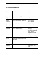
1
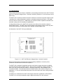
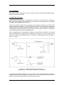
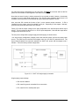
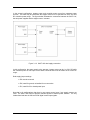
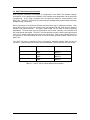
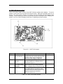
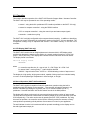
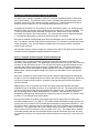
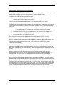
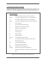
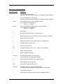
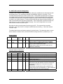
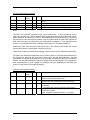
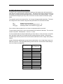
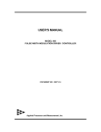
USER'S MANUAL MODEL SACT-100 and SACT-101 ELECTRONIC STEPPER MOTOR / ACTUATOR CONTROLLER DOCUMENT NO. 00130-10 Applied Processor and Measurement, Inc. NOTICE The information contained within this manual has been carefully checked and is believed to be accurate and up to date. Applied Processor and Measurement, Inc. operates under the guidance of quality standards which include activities governing continuous improvement. Applied Processor and Measurement, Inc. may in the future make changes to this product or this manual, without notice, to improve the product reliability, performance, function, or design. Please refer to our website at www.appliedprocessor.com for product updates, software revisions, and hardware revisions. Customers are welcome to use the links on the website to contact Applied Processor and Measurement, Inc. at any time for information on their product version, potential future versions, or customizations of the product for your particular application. Copyright © 2009 – 2014 by Applied Processor and Measurement, Inc. All Rights Reserved -1- REVISION HISTORY Rev Date Pages Description - 7/6/09 All Initial Release A 1/28/10 Various Changes for Rev 1.0 Hardware and Software B 3/19/14 5 8 15 21 Description of analog position output in manual mode - updated features list - updated status output table - added paragraph to section 4.4 - added K17 and K21 to cycle mode settings table -2- SAFETY SUMMARY THE FOLLOWING GENERAL SAFETY PRECAUTIONS MUST BE OBSERVED DURING OPERATION AND INSTALLATION OF THIS PRODUCT. FAILURE TO COMPLY WITH THESE PRECAUTIONS AND WARNINGS HERE, AND ELSEWHERE IN THIS MANUAL VIOLATES THE WARRANTY, THE SAFETY STANDARDS OF DESIGN, MANUFACTURE, AND INTENDED USE OF THIS PRODUCT. APPLIED PROCESSOR AND MEASUREMENT, INC. ASSUMES NO LIABILITY FOR THE FAILURE TO COMPLY WITH THE SAFETY RECOMMENDATIONS PROVIDED IN THIS MANUAL. INTENDED USE The SACT-10X Electronic Actuator Controller is intended to be used in a commercial, laboratory, industrial, or automotive (passenger compartment) environment. It is not intended for use in, or in conjunction with, any medical or life support appliances, devices, or systems. Other than automotive (passenger compartment) applications, the device is not designed for outdoor use. Applied Processor and Measurement, Inc. assumes no liability from the use of this design in this context. Applied Processor and Measurement, Inc. does not assume any liability for the malfunction of electronic components contained in any of its products nor any damage incurred from the improper use of the product to the user, product, or any connecting equipment. GROUND THE SYSTEM Even though the SACT-10X Electronic Actuator Controller requires an external DC source, care should be taken that the total system is properly grounded. Use only power supplies that have three conductor AC power cable with the grounding wire properly connected to an electrical (safety) ground. This will minimize shock hazards. DC POWER ONLY The SACT-10X Electronic Actuator Controller requires a nominal external DC source of 12V DC. Do not connect the SACT-10X Electronic Actuator Controller directly to 120 or 240 V AC. DO NOT SERVICE THE UNIT Do not attempt to service the unit. NEVER open the unit while it is operating or powered. Do not attempt to substitute parts or modify the system internally. -3- 1.0 Introduction This manual describes the features, installation, and operating instructions for the SACT-100 and SACT-101 Electronic Stepper Motor / Actuator Controller (referred to in this document as the SACT-10X). The SACT-10X Controller provides an electronic interface to command a unipolar stepper motors / actuators from a manual pushbutton interface, a standard (computer) serial port, or via digital I/O from a device such as a PLC. Additionally, the controller is able to operate the actuator in an automatic cycling mode for durability test applications. A distinguishing feature of the SACT-10X controller is the ability of the controller to detect a stalled stepper motor. The SACT-10X monitors stepper motor winding current at each step and monitors the waveform for abnormalities which indicate a stalled stepper motor. An illustration of the SACT-100 is provided below. Figure 1.0-1. SACT-100 Electronic Stepper Motor / Actuator Controller. Refer to the figure above throughout this manual regarding installation, connector pinout, pushbutton and slide switch controls and operation. The SACT-10X is intended for applications where small electric stepper actuators are applied, such as automotive HVA/C module controls. With its built-in pushbutton / display interface, the SACT-10X is one of the most cost effective, completely stand-alone, manual stepper motor controllers available. The stall feature allows for determination of the number of steps for your application, or, it can be used to determine points in the travel where the motor is being stressed or hung-up. The SACT-101 is identical to the SACT-100 except for the built-in pushbutton / LED interface. The SACT-101 can only be operated using the digital and analog I/O or the serial port. -4- 1.1 Features The following is a summary of the feature set of the Applied Processor and Measurement, Inc. SACT-100 and SACT-101 Electronic Stepper Motor / Actuator Controller. single stepper motor output for unipolar stepper motor drive configurable stepper frequency from 100 to 300 Hz 16 pulse start-up pulse ramp, configurable in controller non-volatile memory >2A stepper motor peak drive at nominal 12V using open-drain power MOSFET transistors built-in current sensing with motor stall detection algorithm 3 control methods manual positioning using built-in pushbuttons and 8 character alphanumeric LED display (pushbutton / LED interface on SACT-100 only) RS232 computer interface digital input / output signals two automatic cycling control modes cycle from end to end, detecting stall conditions at each end cycle a configurable number of steps controller monitors motor step counting to +/- 30,000 steps highly configurable operation, including controller action on stall detection, stored in controller non-volatile memory two opto-isolated digital inputs: move CW or move CCW two digital outputs: stepper pulse output and stall indicator two analog outputs: actuator average current out and actuator position out input power, 9 to 28V DC at approximately 80 mA input power reversal protection with resettable fuse protection for controller circuitry stepper motor power, 1 to 50V DC, resettable fuse protection in-system reprogrammable microcomputer based controller, field reprogrammable for upgrades and new features rugged, metal enclosure, approximately 3 in. x 5 in. x 1 in. industrial temperature range: -25 to 60 Deg C operation I/O connections using high quality 3.81mm pluggable terminal strips with screw down connections high reliability, multi-layer circuit board construction, using surface mount technology -5- 2.0 Specifications and Pinout Parameter Description Rating Stepper Coil Output Current Open-Drain Power MOSFET 4A typical at 12V Stepper Frequency Stepper Output Frequency, 1 stepper pulse 100 Hz (minimum) 300 Hz (maximum) Internal Stepper Frequency Source Crystal Oscillator Circuit 18.432 MHz, 50 ppm stability Input Power range of operation 9 to 28V DC SACT-100 80 mA (typical at 12V DC) Note: SACT-100 controller current varies and depends on main display LED pattern. SACT-101 35 mA (typical at 12V DC) RS-232 TX, RX, GND, 9600 baud, no parity, 8 data bits, 1 stop bit Operating Temperature -25 °C to 60 °C Dimensions 3.0 in. x 5.0 in. x 1.0 in. height -6- Serial Port Connector (DB9) Connector Pin Name 2 3 5 TX RX Gnd Board I/O Output Input - Description RS232 transmit data RS232 receive data system ground Controller Power Input Connector Pin Name Description 1 + power input 2 - power input from external power supply +9 to 28 V DC single supply configuration +1 to 50 V DC dual supply configuration system ground Notes: 1. Important! See installation diagrams in section 3 for power configurations. The single supply configuration is the factory default setting. 2. The controller board power contains a diode for reverse power protection. Note that the actuator power is not reverse power protected. Actuator / Stepper Motor Output Connector Connector Pin Description 1 2 3 4 5 6 + power output no connection / GND actuator driver output actuator driver output actuator driver output actuator driver output Notes: 3. Connector pin 2 may be connected to system ground using internal jumper JP2. Stepper Motor Drive Sequence Stepper Terminal Strip Pin 3 4 5 6 CW Drive Pin Enabled Drive Pin Enabled X X X X Direction Drive Pin Enabled X CCW Drive Pin Enabled X X X Notes: 4. Pins must be connected in proper order or actuator will not step properly. -7- Control Input Connector Connector Pin 1 Name CW+ Board I/O Input 2 3 CWCCW+ Input Input 4 CCW- Input Description Clockwise move command input (Note 5). Apply 5V to 24V across pins 1 and 2 to command the board to move the actuator CW. Opto-isolated input. Opto-isolator LED current controlled with 4.7kΩ resistor on the circuit board. CW negative input, not connected to system ground. Counterclockwise move command input (Note 5). Apply 5V to 24V across pins 1 and 2 to command the board to move the actuator CCW. Opto-isolated input. Opto-isolator LED current controlled with 4.7kΩ resistor on the circuit board. CCW negative input, not connected to system ground. Notes: 5. The board will process one command, CW or CCW, whichever is received and acted upon first. Do not apply CW and CCW simultaneously. It is required that both commands are off for at least 10 msec for the software state machine to stop and re-start move commands. Subsequent commands will be ignored until the original command is removed. Status Connector Connector Pin 1 Name Board I/O Input / Output Power 2 Pulse Output 3 Stall Output 4 Position Output 5 Current Output 6 Ground Output Description Output power equal to input power if JP5 is installed for single power supply operation. Input for controller board +9 to 28V DC power only if JP5 is not installed for the dual power supply configuration. Pulse output. Active when controller is moving stepper/actuator and not in stall condition (configurable). Pulse amplitude of 5V or input power depending on JP1 setting. Stall indicator. Active when board receives command to move CW or CCW and a stall condition is detected. The deassertion of the indicator and the controller action regarding the stepper/actuator is configurable. See section 4. Pulse amplitude of 5V or input power depending on JP1 setting. Analog output. Output will be 0 to 5V, proportional to relative position over a number of steps. Average output current of the stepper/actuator. Output scale of 5mV = 1mA. system ground – all outputs on this connector are referenced to the system ground. Notes: 6. Important! See installation diagrams in section 3 for power configurations. The single supply configuration is the factory default setting. 7. JP1 and JP5 settings are described in the installation section of this manual. 8. Important! The maximum voltage allowed on the pulse output driver is 16V DC. If the input voltage is greater than 16V DC, then the pulse output amplitude must be 5V. See installation section for jumper setting information. -8- 3.0 Installation This section provides information on how to connect the SACT-10X Electronic Stepper Motor / Actuator Controller for operation. 3.1 SACT-10X Connection Use the figures below and the pin descriptions in Section 2.0 of this manual to connect the SACT-10X to your stepper motor / actuator. Note that currently, only stepper motors configured as unipolar are supported by the SACT-10X. There are two basic connections for the stepper motor / actuator connection to the SACT-10X: single supply and dual supply. The single supply connection may be used when the actuator voltage is within the range of controller voltage of 9 to 28V DC. The dual supply connection is required when the actuator operating voltage outside of the 9 to 28V DC range, or, if you wish to use a separate power source for the actuator power. First, an explanation of the internal power routing in the SACT-10X is provided. The internal power routing allows for a wide variety of stepper motor voltages to be used, utilizing the full range of the output power MOSFET drivers. The SACT-10X internal power routing is shown in figure 3.1-1 below. Figure 3.1-1. SACT-10X internal power connection. Factory Default: JP5 installed, JP2 open, JP1 for 5V power. If a single power supply configuration is to be used, then JP5 may be installed and power is applied to the Power Input connector on the SACT-10X. In this configuration, the input power is output on the actuator output connector and the Status Connector. -9- If a dual power supply configuration is to be used, then JP5 MUST be removed, and 9 to 28V DC power for the controller must be applied to the Status connector. Note that the board circuitry is diode protected for input power reversal, however, the actuator connector is not (to avoid diode voltage drop). The actuator power connector does have a 2.5A resettable fuse for protection of the actuator and the output power MOSFET drivers. Also, note that JP2 controls the function of pin 2 on the actuator output connector. If JP2 is installed, then the system ground is available on this pin. Depending on the stepper / actuator, ground or two power pins are wired to the actuator. Finally, JP1 sets the output voltage for the pulse amplitudes of the stall and pulse status output drivers. This is provided to allow for 5V or 12V DC pulse amplitudes, Note that the output driver voltage must not exceed 16V DC. The two power configurations (single supply and dual supply) are shown below. In a single supply configuration, stepper power and controller power are from the same power source. This case may be used when the stepper motor is a 9 to 28V DC powered device. The figure below illustrates the connection between the SACT-10X, power and the stepper motor / actuator. This is the factory default configuration. Figure 3.1-2. SACT-10X single supply connection. Single supply jumper settings: JP5 must be installed JP2, install for ground, uninstalled for no connection JP1, install for 5V or board power input - 10 - In the second configuration, stepper power and controller power come from separate power sources. This case may be used when the stepper motor is to be operated out of the 9 to 28V DC controller power range. The figure below illustrates the connection between the SACT-10X, the two power supplies and the stepper motor / actuator. Figure 3.1-3. SACT-10X dual supply connection. In this configuration, the power supply to the actuator / stepper motor can be 1 to 50 V DC while the controller power is now input on the Status connector and must be within the 9 to 28V DC range. Dual supply jumper settings: JP5 must be removed JP2, install for ground, uninstalled for no connection JP1, install for 5V or board power input Note that in all configurations, that there is one system ground even if two supply sources are used. The SACT-10X does not provide controller power to actuator power isolation. The only isolated terminals are the CW and CCW digital control input signals. - 11 - 3.2 SACT-10X Peripheral Connections Host computer connection is necessary for configuration of the SACT-10X software settings. See Section 4.2 for details on the operation of the controller and configuration via the serial port command set. A PC using a program such as HyperTerm allows for communication to the SACT-10X. The SACT-10X may be connected using a standard DB-9 (female-female) cable with straight through connections. Other connections to the Control and Status terminal blocks may be made as necessary. Note that a device such as a PLC may connect to the opto-isolated CW and CCW inputs to control a stepper motor based actuator. The pulse output signal can be used for exact positioning applications. The stall output may be monitored for end of travel, indexing, or an indication that the motor/acuator has seized. The SACT-10X also provides a motor current output signal as well as a 0 to 5V relative positioning signal for motor cycling tests. Refer to the operation section of this manual for more information on how to use the control inputs and status outputs on the SACT-10X. The SACT-10X uses a standard 3.81mm, screw-down, pluggable terminal block for the I/O connection. Replacement part numbers are provided below. The components are rated for 8A. Connector Manufacturer Part Number 2 pin Phoenix AMP Phoenix AMP Phoenix AMP 1803578 284507-2 1803594 284507-4 1803617 284507-6 4 pin 6 pin Table 3.1-1 SACT-10X I/O Terminal Block Part Numbers. - 12 - 3.3 SACT-10X Internal Jumpers There are several jumpers internal to the SACT-10X that configure the hardware. To set the jumpers, remove the cover and orient the board as below. Note that the display board is not shown in the figure below, however, all jumpers are still accessible with the display board installed. Avoid touching the circuits on the board as best as possible while modifying the jumpers. Be sure to static discharge yourself prior to adjusting the jumper settings. Figure 3.3-1. SACT-10X Jumpers. Jumper Description Setting Factory Default JP5 Controller Board Power Selection Installed JP2 Actuator Output Ground JP1 Pulse Out and Stall Out Signal voltage amplitude RS232 5V power If this jumper is installed, the power input supplies both the controller board and the actuator (single supply configuration). Remove for dual supply configuration. Install JP2 for ground connection on Actuator Output pin 2. Remove for no connection on pin 2. Left 2 pins for 5V amplitude. Right 2 pins for input voltage amplitude. Note: amplitude may not exceed 16V DC. Allows for 5V power to be applied to pin 9 of the DB-9 RS232 connector for handheld terminal device power (50mA or less). Upper two pins for no connection. Lower two pins for 5V. JP4 Table 3.3-1 SACT-10X Jumper Settings. - 13 - Removed 5V No Connection 4.0 Operation This section describes operation of the SACT-10X Electronic Stepper Motor / Actuator Controller. The SACT-10X may be operated in one of four operating modes: manual – using the built-in pushbutton LED interface (available on the SACT-100 only) manual or computer controlled – using the RS232 interface PLC or computer controlled – using the control input and status output signals automatic – stand-alone cycling The SACT-10X is a highly configurable microcomputer based controller. In addition to describing the serial port control commands, the configuration options of the SACT-10X are described. The configuration settings may be adjusted and saved in non-volatile memory in the SACT-10X controller. 4.1 LED Display (SACT-100 only) The SACT-100 Controller has an 8 digit alphanumeric character built-in LED display which continuously displays the stepper motor position in a signed number format from +32767 (full CW) to –32767 (full CCW). The display also indicates movement direction and motor status. The display format is as follows: SACT-100 Display Format ABXXXXXX where A = controller step direction, H = stop or halt, C = CW / Right, W = CCW / Left B = status, blank = moving freely, T = stall condition detected XXXXXX = signed number from –32767 to + 32768 indicating number of steps moved The display is a high quality, bright green module, capable of being used in an industrial setting or even in a vehicle passenger compartment in direct sunlight, or at night. 4.2 Manual Operation (SACT-100 Pushbuttons) The SACT-100 Controller is capable of manual, stand-alone operation using the built-in pushbuttons and LED display on the controller. The controller will step the actuator in the direction indicated by pressing the clockwise (CW / R) or counterclockwise (CCW / L) pushbutton. Note that the MAN / AUTO slide switch must be in the MAN position. The display will indicate continuously the movement direction and the number of steps moved. The step value will increment or decrement cumulatively based on the current direction (CW and CCW respectively). The value can be reset by pressing the RST / ENT pushbutton. By using this mode of operation, the controller can be used to manually position the actuator to nearly exact positions representing critical positions of an actuator or control in your application. The stall indicator is active in this mode and will be reported accordingly on the display and on the stall signal status output pin. - 14 - 4.3 Manual / Computer Controlled Serial Port Operation The SACT-10X Controller is capable of manual or computer controlled operation via the serial port on the controller. The serial port may be used to command the controller by using a host computer such as a PC with a terminal emulator (HyperTerm). Control programs may also be written for a host computer or PLC to command and control the SACT-10X. To operate the controller from the serial port use the commands in section 4.6. When using the serial port control, the actuator may be positioned exactly using the ‘C’ and ‘W’ commands. The ‘C’ and ‘W’ commands may be issued with an exact count. Note that the moves with these commands are relative to the current position. The current position may be displayed using the ‘V’ command and the position count may be zeroed using the ‘Z’ command. Note that the external actuator digital inputs and the pushbuttons work in parallel with the serial port. For example, the step count can be zeroed using the ‘Z’ command or by pressing the reset / enter pushbutton. Also, the LED display will display moves and step counts for commands issued via the serial port. The serial port must be used to configure the settings for the SACT-10X. Refer to the commands in section 4.6 and configuration settings described in section 4.7. 4.4 PLC / Computer Control using the Control and Status I/O The SACT-10X Controller possesses 2 digital input controls which allow for CW and CCW movement of the stepper motor. The digital input controls are present on 4 pins of the Control I/O connector on the right side of the unit. The CW and CCW inputs are optically isolated from the controller and actuator power supply and have 4 independent pins. The inputs are designed (with an internal current set resistor) to accept signals from 5V to 24V nominal for PC and PLC digital outputs. Appling the digital voltage to the proper input will enable CW or CCW actuator movement. Note that it is possible to relative position the actuator using the digital inputs and timed signals. A pulse of 1 sec and a stepper frequency of 250 Hz will move the stepper 250 steps. Moves may be off due to system timings, however, a periodic re-zeroing sequence could be performed to home the actuator. Additionally, the PLC or computer may monitor the digital output pulse and the stall signal available on pins on the Status connector on the right side of the unit. The output pulse provides one active high pulse for each step commanded to the stepper motor. The stall indicator signal will go active high when a stall is determined by the controller. Note that there are several configuration settings for the stall output such as pulsed or latched, and when it is cleared. Refer to section 4.7 for setting the stall output options. During manual mode, the position status output signal can be configured to be active (note: controller software version 1.3 or higher). The position output will provide an output from 0 to 5V in proportion to the position in the movement span as defined by configuration constant 21. 0V is full CCW (or home / reset zero) and 5V corresponds to full CW (or full span move as defined by constant 21). The proportional output level is determined by the number of steps in the actuator travel over the move from position 0 (=0V) to position ‘K21’ (=5V). The analog value in between is calculated linearly and output to the analog output signal as the actuator is moved. Any step count below 0 will result in 0V output and any step count above the value of K21 will result in 5V output. - 15 - 4.5 Automatic / Stand-Alone Cycling Operation The SACT-10X controller may be used in an automatic cycling mode of operation. The mode can be used to actuate devices in a long term test or product validation tests. The SACT-10X Controller can cycle test in two ways: - cycling from end to end of travel, detecting stall at each end - cycling a fixed number of steps each direction There is also a programmable dwell time that is executed at the end of each move. The SACT-10X must be configured to operate in one of these cycling modes prior to entering the cycling mode. It is necessary to configure the number of steps to move in one direction and the dwell time. a. set the number of steps to move in one direction using the K14 setting o note that a setting of 0 will direct the controller to cycle from stall to stall o a setting of other than 0 will direct the controller to move that number of steps b. set the dwell time (time to stop at each full-CW and full-CCW end) by using the K15 setting, 1 count per 0.005 sec of dwell time c. save the settings in non-volatile memory (KV) Enter the cycle mode by moving the slide switch from MAN to AUTO (SACT-100 only). When in automatic cycling mode the motor/actuator will be stepped to the full CW direction, wait the dwell time, then move back CCW to the full CCW direction, and then dwell at the start position before continuing with another cycle. At the end of each cycle the cycle count is incremented on the display. By default, the display shows the cycle count. By pressing the CCW pushbutton, the step counts may be monitored. By pressing the CW pushbutton, the cycle count is displayed. Pressing the RST / ENT pushbutton will zero the cycle count. Note that the stall indicator is also active during cycling. With the alphanumeric LED display, the cycle count is lost when power to the controller is removed. Also, the cycle count is only displayed when in the auto mode (steps displayed in manual mode). The cycle count may be displayed and zeroed at any time via serial port commands. During cycling, the pulse, stall and position status output signals are active. The pulse output and stall output function normally and will output stepper pulses and a stall condition respectively. The position output will provide an output from 0 to 5V in proportion to the position in the cycle. 0V is full CCW (or home) and 5V corresponds to full CW (or span). The proportional output level is determined by the number of steps in the cycle travel. In the mode where cycling is performed from stall to stall, the controller will automatically learn a step count in the first 2 to 3 complete cycles. In the cycle mode with a fixed count, this fixed count is used for the proportion. - 16 - 4.6 SACT-10X Controller Serial Port Commands Features of the SACT-10X Controller are controlled via an ASCII character command set. All commands are terminated by a carriage return (Return, Enter Key on your keyboard - ASCII value of 0x13). A summary of all Model SACT-10X Controller commands is shown in table 4.6-1. SACT-10X Commands C - move CW until Stop or Halt issued, or stall (if configured) Cxxxxx - move CW [1..30000] steps, then stop, or on stall (if configured) W - move CCW until Stop or Halt issued, or stall (if configured) Wxxxxx - move CCW [1..30000] steps, then stop, or on stall (if configured) H - stop (halt) actuator S - stop actuator (same as Halt command) V - display step count and cycle count values VT - display value for stall adjustment T - display motion status Z - zero step counter ZC - zero cycle counter K - display configuration Kxx,yyyyy - set configuration variable xx to yyyyy KV - save configuration settings in controller non-volatile memory F - display stepper frequency Fxxx - set [100..300] stepper frequency R - display stepper start-up sequence RSxx - set number of sequence steps [0..16] Rxx,yyyyy - set start-up step xx to yyyyy [2000..25000] usec I - display system information – serial number and software version ? - help Table 4.6-1 SACT-10X Controller Serial Port Command Summary - 17 - All RS-232 commands are via standard ASCII characters. The serial interface is set for 9600 baud, no parity, 8 data bits, 1 stop bit, and no hardware handshaking. Note that character positioning is important, do not add extra spaces or punctuation. Characters may be entered in uppercase or lowercase. Backspace may be used to correct entries on a command line. (Do not set backspace translation on the terminal emulator – terminal emulator must send one ctrl-H only.) The end of the command line signals to the microcomputer software to process the command line. The SACT-10X utilizes a small microcomputer IC, there is in-sufficient memory to buffer many commands. When using computer control for the SACT-10X, be sure to wait for the command prompt before sending additional commands, or, use an interline delay of at least 1 second. Detailed descriptions of the SACT-10X Controller commands are provided on the following pages. - 18 - SACT-10X Command Descriptions: Command Format Description c move clockwise continuously continues until stop command issued, or if configured, a stall is detected w move counterclockwise continuously continues until stop command issued, or if configured, a stall is detected cxxxxx move clockwise xxxxx number of steps, then stop, or if configured, a stall is detected xxxxx = [1 … 30000] wxxxxx move counterclockwise xxxxx number of steps, then stop or if configured, a stall is detected xxxxx = [1 … 30000] s stop actuator h halt (stop) actuator, same as ‘s’ command above t display motion status (C=CW, W=CCW, H=halt, T=stalled, Y=cycling) v display actuator step counter vt display average peak value of stall detector for pot adjustment z set actuator step counter to zero zc set cycle counter to zero fxxx set stepper frequency, xxx = [100 … 300] Hz, 1 Hz resolution f display stepper frequency k display configuration settings kxx,yyyyy set configuration setting xx to the value yy refer to section 4.7 for configuration settings kv save configuration settings in non-volatile memory r display stepper start-up sequence rsxx set number of sequence steps [0..16] rxx,yyyyy set start-up step xx to yyyyy [2000..25000] usec see section 4.8 for information on start-up sequence and settings ? help, display commands i report system information (serial number and software revision) - 19 - 4.7 SACT-10X Controller Configuration The SACT-10X Controller is highly configurable, allowing for settable actions when detecting stall and indicating stall. The configuration settings are adjustable using the K command. The K command sets a parameter by number, then its value. Configuration commands are not saved in non-volatile memory until the save command is issued. It is recommended that the configuration commands be issued and the configuration display command is used to check the settings prior to saving in non-volatile memory. It is also recommended that the actuator be disconnected, or at least not commanded (moving) during configuration. Some configuration commands conflict with other settings, be sure to review the table thoroughly. Also, some configurations do not take effect until the controller is power cycled. Note that the values must be entered in as Kxx,yyyyy<CR>. The command line is position dependent, so the value for K3 for example must be entered in as K03,yy. Values are checked for proper range. The tables below list the configuration settings by logical function. The tables also have a column which indicates the default value, and which mode the setting has effect in (indicated by an ‘X’). System Settings Kxx value range 01 100..300 default value 250 03 0..25 8 man auto X X X - description stepper frequency (Hz) – note this is the same as the Fxxx command, F is kept for backward compatibility debounce timer for digital inputs (1 count = 5 msec) if set to 0 then no debounce is used if digital inputs signals only are to be used, then no debounce is necessary Controller Action on Stall Detect Kxx value range 04 05 06 0,1 0,1 0,1 default value 0 0 0 man auto X X X X 07 08 0,1 0,1 0 1 X X - 09 1..500 200 X - description stop actuator on stall detect (N=0, Y=1) stop step counter on stall detect (N=0, Y=1) clear stall indication on stop or next move command (stop=0, next move=1) stop output pulse on stall detect (N=0, Y=1) pulse or latch stall indicator (latch=0, pulse=1) when latched, the stall indicator will not be cleared until the actuator is stopped or on the next move (as per setting K06) when pulsed, the stall indicator will be pulsed for the amount of time given by setting K09, or, when cleared as per setting K06 (on stop or next command) stall indicator pulse time (1 count = 5 msec) - 20 - Controller Stall Detection Settings Kxx value range 10 8..500 default value 32 11 12 13 1..50 1..50 1..100 2 3 4 man auto X X X X X X X X description number of pulses on a move before stall determination is active stall detection ratio – numerator (see note) stall detection ratio – denominator (see note) stall event counts before stall is triggered (see note) Note: The SACT-10X Controller measures motor current continuously. A circuit provides a filtered, peak value for each step. Stall is determined by monitoring the wave shape of the motor current. When not stalled, the waveform is uniform. When stalled the non-uniform waveform is sensed by the peak circuit and microcomputer software. Stall is triggered when the peak value is below the peak value average by the ratio given by the configuration constants K11 / K12. Making the ratio closer to 1 increases stall sensitivity, making the ratio closer to 0, decreases sensitivity. Additionally, there is a event counter that may be used. The number of stall events are counted and the stall indicator is not triggered until the count is met. Finally, there is also a pot setting to be adjusted. Refer to section 4.9 for adjustment instructions. The SACT-10X stall detection algorithm can be sensitive and can yield false stalls depending on the environment. Stress on the motor can be picked up by the stall detect algorithm – this may be desirable in engineering development so as to be able to find stress points in the mechanical system. Use the stall parameters to adjust the sensitivity as best as possible for your application. Also, contact APM, Inc. product support for assistance with your application as necessary (see section 5 of this manual for contact information). Automatic Cycling Mode Settings Kxx value range 14 0..30000 default value 0 15 1..12000 100 17 0,1 21 0..30000 man auto - X - X X 0 X - description span – amount of steps to move during a half cycle If set to 0, then cycle is stall to stall cycle mode dwell time (1 count = 5 msec) controller will wait this amount of time at each end pulse output during cycling 0 = stepper 1 = one pulse per cycle (for external cycle counting) analog output step count span during manual mode, 0 value for no output Note: available in controller version 1.3 or higher - 21 - 4.8 SACT-10X Stepper Start-up Sequence The SACT-10X Controller has the capability of starting up the stepper motor with step times of other than the operating frequency (pulse period). This is done such that the stepper motor may be brought up to speed using slower step times for the first few motor stepping pulses. The step is executed at the beginning of every CW or CCW move in either manual or automatic cycling mode. The controller may be set to execute from 1 to 16 steps of programmable step times. The times are configured in to the controller using the serial port and the ‘R’ commands as follows: R RSxx Rxx,yyyyy displays the current settings sets the number of start-up steps to use [0 .. 16] sets step number xx to a duration of yyyyy usec If the number of start-up steps is set to 0, then no ramp steps shall be executed. To set the start-up step time, a count must be entered into controller for that step. The count is a number from [2000 .. 25000] where 1 count is = 1.0 usec. It is recommended that the steps be descending in count value (i.e. time), from step 1 to the last step, and that the last step is not smaller than the operating frequency period. Note that the command input does not prevent incorrect time entries other than an out of range value (2000 to 25000). A table of the factory default start-up ramp times is given below, it is an 8 step linear ramp up to 4000 usec (250 Hz). This is the default setting for the controller. Note that the default setting is not to use a start-up ramp (RS0). Ramp Step Default Value Step Time (usec) 01 02 03 04 05 06 07 08 09 10 11 12 13 14 15 16 8000 7500 7000 6500 6000 5500 5000 4500 4000 4000 4000 4000 4000 4000 4000 4000 - 22 - 4.9 SACT-10X Stall Signal Adjustment The SACT-10X Controller has the capability of sensing stepper motor stall. There is one hardware adjustment that sets the amplitude of the stall signal fed to the microcomputer for analysis. The amplitude can vary widely based on the current required to operate the stepper motor, therefore, it may be necessary to adjust this setting for optimal controller stall sensing. Open the cover of the SACT-10X unit. The pot labeled R40 must be adjusted (refer to figure 3.31 for location on circuit board). For best results, it will be necessary to: - have a serial port connection to the SACT-10X have the target actuator connected to the SACT-10X have the target actuator able to move freely (will not stall or mechanically hang-up) NOTE: Although there are only low DC voltages inside the controller, be careful not to touch circuits inside the SACT-10X during this procedure. To adjust the stall gain setting, use the following procedure: - start the stepper actuator using the c or w command from the serial port using the vt command, readout the peak voltage for the stall determination a setting of about 600 is desired if the setting is low, turn the pot CW to increase the setting, use the vt command to set if the setting is too high, turn the pot CCW to decrease the setting, use the vt command to set continue using the vt command to readout the setting until a value of about 600 is obtained (the value may not be perfectly stable, estimate as best as possible) The setting at R40 is factory adjusted for a stepper actuator peak current of about 1A and should operate for peak current outputs of about 0.5A to 1.5A (or greater) without adjustment. The value can be checked. If the vt command output yields a result of greater than 900 or less than 200 it is best to adjust the setting at R40. - 23 - 5.0 Warranty and Product Support 5.1 Warranty The SACT-10X Controller is warranted for 90 days from the time of purchase. This includes workmanship and manufacturer defects. It does not include failures caused by misuse. 5.2 Service WARNING THERE ARE NO USER SERVICEABLE PARTS INTERNAL TO THE SACT-10X CONTROLLER. DO NOT ATTEMPT TO SERVICE THE UNIT. COMPONENTS INTERNAL TO THE CONTROLLER ARE STATIC SENSITIVE AND MAY BE DAMAGED WITHOUT PROPER HANDLING. The SACT-10X Controller requires no maintenance or calibration. If you detect a malfunction with your unit, obtain a Return Authorization (RA) Number from the Applied Processor and Measurement, Inc website. Information on how to have your unit serviced, the shipping address, and service policies are shown on the website. You must obtain an RA number for either warranty or non-warranty service. There is a minimum service charge for non-warranty service. Applied Processor and Measurement, Inc. will repair or replace the unit at its option. If the return is for non-warranty repair, you will be notified of any applicable charges prior to work being performed. Applied Processor and Measurement, Inc. may be contacted as follows: Applied Processor and Measurement, Inc. Phone: FAX: E-mail: URL: (716) 741-1141 (716) 741-1142 [email protected] www.appliedprocessor.com 5.3 Diagnostics The SACT-10X Controller output is a basically a stepper motor output with an open drain FET, generating pulses in sequence on the 4 outputs. Therefore, any test equipment used to detect or measure signals may be used to check the stepper output. If it appears that you are still in communication with the SACT-10X Controller, but you are in doubt of the SACT-10X output, simulate the stepper motor by connecting a resistor from one of the outputs to V+. Depending on the level of diagnosis desired, any of the following methods may be used to determine whether the SACT-10X Controller is generating an output signal. In all cases, the frequency out on one pin should be ¼ of the stepper frequency set in the controller. Oscilloscope - best method of observing the output. The stepper pulse may be observed and measured. Frequency Counter - will be able to measure the output frequency. Some DMM’s have frequency measurement capability. - 24 - DMM - setting the DMM to measure DC Volts will provide some “average” value of voltage that will allow you to conclude that the stepper output is not stuck high or low. In conclusion, do not attempt to service the SACT-10X Controller internally. The methods provided above give a visual indication of operation of the unit. This indication is intended to isolate problems with your application of the controller to the unit itself or the system connection. 5.4 Software Upgrades / Updates The SACT-10X Controller contains in-circuit programmable microcomputer based circuitry and software. Applied Processor and Measurement, Inc. is committed to supplying a high quality product and will issue new software releases which will enhance capability and maintain the software. When purchasing the SACT-10X Controller, your unit will be automatically registered. This registration will allow you to receive notices and pricing information on software releases and new software versions containing operational enhancements and new features. The SACT10X Controller software is capable of being upgraded for the life of the unit. Watch our website for information on available software revisions for the SACT-10X Controller. The unit may be returned to APM, Inc. for upgrade (minimum service charges apply), or, the unit may be field upgraded from a PC with a utility supplied by APM, Inc. 5.5 SACT-10X Product Support APM, Inc. product engineering support is available to evaluate your stepper motor / actuator for use with the SACT-10X. This includes the evaluation of the most effective stall settings and the ability to detect stall properly. Sample motors and specifications may be sent to our engineers for evaluation. Please use the contact information below. The SACT-10X is a highly flexible, microcomputer based device. The output of the unit may be easily modified to support other motor and actuator types. Contact APM, Inc. for support for your actuator. Applied Processor and Measurement, Inc. may be contacted as follows: Applied Processor and Measurement, Inc. Phone: FAX: E-mail: URL: (716) 741-1141 (716) 741-1142 [email protected] www.appliedprocessor.com - 25 - 5.5 Customization & Engineering Additionally, the SACT-10X (as well as other APM, Inc. PWM and interface products) may be easily and cost effectively modified to suit your specific application. Call and discuss your requirements with one of our engineers. Our engineering staff has extensive experience in test applications and embedded system applications. Applied Processor and Measurement, Inc. will respond quickly with a quotation upon your request. For customizations, further information and controller purchase, contact: Applied Processor and Measurement, Inc. Phone: FAX: E-mail: URL: (716) 741-1141 (716) 741-1142 [email protected] www.appliedprocessor.com Applied Processor and Measurement, Inc. engineers have been designing microprocessor based instrumentation and embedded control systems since 1980. We welcome inquiries on custom designs, variations on this design, as well as customized software for your application. Call and discuss your embedded control requirements with one of our engineers. - 26 -