1
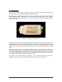
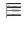
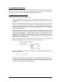
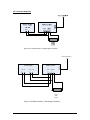
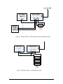
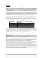
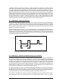
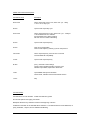
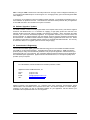
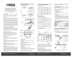
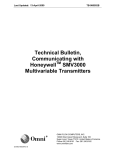
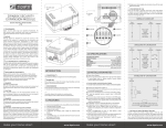
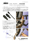
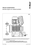
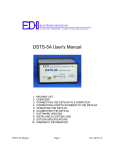
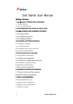
USER'S MANUAL
MODEL 402
PULSE WIDTH MODULATION DRIVER / CONTROLLER
DOCUMENT NO. 00092-23
Applied Processor and Measurement, Inc.
NOTICE
The information contained within this manual has been carefully checked and is believed to be accurate and
up to date.
Applied Processor and Measurement, Inc. operates under the guidance of quality standards which include
activities governing continuous improvement. Applied Processor and Measurement, Inc. may in the future
make changes to this product or this manual, without notice, to improve the product reliability, performance,
function, or design. Please refer to our website at www.appliedprocessor.com for product updates, software
revisions, and hardware revisions. Customers are welcomed to use the forms on the website to contact
Applied Processor and Measurement, Inc. at any time for information on their product version, potential
future versions, or customizations of the product for your particular application.
Copyright © July 2009 by
Applied Processor and Measurement, Inc.
All Rights Reserved
-1-
REVISION HISTORY
Rev
-
Pages
Date
7/2/09
All
Description
Initial Release
-2-
SAFETY SUMMARY
THE FOLLOWING GENERAL SAFETY PRECAUTIONS MUST BE OBSERVED DURING OPERATION
AND INSTALLATION OF THIS PRODUCT. FAILURE TO COMPLY WITH THESE PRECAUTIONS AND
WARNINGS HERE, AND ELSEWHERE IN THIS MANUAL VIOLATES THE SAFETY STANDARDS OF
DESIGN, MANUFACTURE, AND INTENDED USE OF THIS PRODUCT. APPLIED PROCESSOR AND
MEASUREMENT, INC. ASSUMES NO LIABILITY FOR THE FAILURE TO COMPLY WITH THE SAFETY
RECOMMENDATIONS PROVIDED IN THIS MANUAL.
INTENDED USE
The Model 402 Pulse Width Modulation Driver / Controller is intended to be used in a laboratory / industrial /
automotive (passenger compartment) environment. It is not intended for use in, or in conjunction with, any
medical or life support appliances, devices, or systems. Other than automotive (passenger compartment)
applications, the device is not designed for outdoor use. Applied Processor and Measurement, Inc.
assumes no liability from the use of this design in this context.
Applied Processor and Measurement, Inc. does not assume any liability for the malfunction of electronic
components contained in any of its products nor any damage incurred from the improper use of the product
to the user, product, or any connecting equipment.
GROUND THE SYSTEM
Even though the Pulse Width Modulation Driver / Controller requires an external DC source, care should be
taken that the total system is properly grounded. Use only power supplies that have three conductor AC
power cable with the grounding wire properly connected to an electrical (safety) ground. This will minimize
shock hazards.
DC POWER ONLY
The Pulse Width Modulation Driver / Controller requires a nominal external DC source of 12V DC. Do not
connect the Pulse Width Modulation Driver / Controller directly to 120 or 240 V AC.
DO NOT SERVICE THE UNIT
Do not attempt to service the unit. NEVER open the unit while it is operating. Do not attempt to substitute
parts or modify the system internally.
-3-
1.0 Introduction
This manual describes the features, installation, and operating procedures for the Model 402 Pulse Width
Modulation Driver / Controller (PWM Driver, PWM Controller or PWMC).
The Model 402 Pulse Width Modulation Driver / Controller generates a variable pulse width modulated
electrical switching signal. The product is used in many industrial situations where valves, solenoids,
actuators, magnetic / mechanical elements or other devices requiring a pulse width modulated signal are
applied and / or tested.
Figure 1.0-1 Model 402 PWM Controller.
The PWM Controller contains microcomputer based circuitry which allows for precision generation of the
output frequency and duty cycle. The PWM Controller is controlled via an RS-232 serial interface. Single
letter ASCII based commands allow the duty cycle to be set and displayed. This capability allows the PWM
Controller to be controlled by a host computer serial port (e.g. PC compatible) under program or manual
control.
The PWM Controller output is an open drain power MOSFET output. This provides low side control of the
load to be pulse width modulated. An external power source must be provided, which may be used to power
both the load and the PWMC. This provides maximum flexibility since the load voltage can be set by the
user using any variable bench-top power supply or it can derive power directly from the system under control
(provided the controller is operated within the rated specifications).
The operation of the PWM Controller is configurable. User programmable configuration options are
available to set the power-up state of the PWM Controller, the output frequency and duty cycle.
-4-
1.1 Features
The following is a summary of the feature set of the Applied Processor and Measurement, Inc. Model 402
PWM Driver / Controller.
• user / computer adjustable pulse width modulated output switching signal 0 to 100 % duty cycle
• fixed frequency operation, configurable by user in 1 Hz steps from 10 to 1000 Hz or in 50 Hz steps from
1000 to 1500 Hz
• duty cycle adjustable in 0.1% steps using RS-232 commands
• PWM output provides low side load control
• Power MOSFET output - PWM output sinks up to 4 amps at 12 volts
• fused output using standard mini-blade fuses
• controller operates from same power source that powers the load - an external power source, nominal 12V
DC must be supplied, also supports a dual supply configuration allowing load voltages up to 32V
• input power reversal protection, controller circuitry protected by resettable polyfuse
• inherent PWM monitoring
monitors for open load
monitors for open output fuse
• configurable, controller can power-on at preset frequency and duty cycle
• available with a non-isolated or an electrically isolated RS-232 interface
Model 402R – non-isolated
Model 402T – electrically isolated
• temperature range: -40˚C to 60˚C operation
• high reliability, single multi-layer circuit board construction, using surface mount technology
1.2 Applications
The Model 402 PWM Controller was specifically designed for driving electromechanical devices requiring a
PWM control signal such as solenoid valves or other electromechanical controls with solenoids or inductive
loads. The Model 402 PWM Controller is also suitable for generating a PWM signal to drive electrical
devices that are controlled by a low level PWM signal.
-5-
2.0 Specifications and Pinout
Parameter
Description
Rating
Output Power
Open Drain Power MOSFET
Pd max = 50 watts at 25˚C
Output Current
Example Output Current, 100% duty cycle
Power must not exceed maximum Pd
4A at 12V maximum (at 25˚C)
Output Voltage
Must use dual power supply configuration for voltages not
within PWM Controller Input range
1V minimum
32V maximum
Frequency
10 to 1000 Hz, adjustment resolution of 1Hz
1000 to 1500 Hz, adjustment resolution of 50 Hz
max error < 0.05 Hz
Duty Cycle
0 to 100 %, adjustable in 0.1 % steps,
minimum and maximum duty cycle based on frequency
0% to minimum Æ output duty cycle is forced to 0%
maximum to 100% Æ output duty cycle is forced to 100%
50 Hz, minimum 0.2%, maximum to 99.8%
100 Hz, minimum 0.5%, maximum 99.5%
500 Hz, minimum 1.5%, maximum 98.5%
1000 Hz, minimum 3.0%, maximum 97.0%
1500 Hz, minimum 4.5%, maximum 95.5%
typical error < 0.1 %
Frequency
Source
Crystal Oscillator Circuit
18.432 MHz, 50 ppm stability
Input Power
Nominal 12V DC external source
Model 402R, range of operation, 9 to 28V DC
20 mA (typical)
Model 402T, range of operation 9 to 14V DC
120 mA (typical)
Dual supply required for operating loads outside this range.
RS-232
TX, RX, GND, 9600 baud, no parity, 8 data bits, 1 stop bit
Operating
Temp.
limited by enclosure
electrical components are industrial temperature range
-40 °C to 60 °C
Dimensions
4.25 in. x 1.7 in. x 1.0 in. height
Environmental
Lead-Free
RoHS
-6-
Pin Name
Description / Function
PWMC I/O
VIN +
PWM Controller power input
VIN -
PWM Controller system ground
OUT +
PWM Controller output positive connection
(see note 1)
PWM Controller switching output, open drain power
MOSFET, switches load from open to IN –
(system ground)
OUT -
RS-232 Interface
2
RS-232 Transmit
3
RS-232 Receive
5
Ground
Notes:
(1) The positive output is internally connected to a protective diode (see figure 4-1).
-7-
3.0 Installation and Start-up
This section provides information on how to connect the PWM Controller for operation and provides start-up
instructions. Section 3.1 provides a Quick Start Installation intended to provide an easy step-by-step
procedure to connect and start using the Model 402 PWM Controller (PWMC-402).
3.1 PWMC-402 Quick Start Instructions
Use the following steps to start using the PWMC-402:
1.
Connect the PWMC-402 as shown in one of the installation diagrams in section 3.3. The
connection depends on the load voltage, and the type of load. Use the descriptions in section 3.2
for guidance.
Note that the PWMC-402 may be powered from the same power supply as the load. Be sure to
stay within the operational ratings of the PWMC-402. The PWMC-402R operational range is 9 to
28 V DC, while the PWMC-402T is 9 to 14V DC. A dual supply configuration may be used for
extending the operating voltage of the load. For applications assistance, contact customer support
at www.appliedprocessor.com.
2.
Check that the internal fuse rating is suitable for your application. The factory installed fuse in the
PWMC-402 is rated at 4 Amps. This is sufficient to protect the PWMC-402 output stage in most
12V solenoid / load applications. If you need to protect your load, or your application is not 12V, a
proper fuse should be installed. Consult the section on Fusing in this manual (section 3.4). This
paragraph contains information on selecting the fuse as well as information on the fuse part
numbers used in the PWMC-402 product. A standard mini-blade fuse is used, available in most
hardware and automotive parts stores.
3.
Connect the PWMC-402 to a host computer (such as a PC) and open a serial port communication
application such as HyperTerminal. For HyperTerminal, set it up as follows:
Select the appropriate COM port
Set PORT settings:
4.
Bits per second:
Data Bits:
Parity:
Stop Bits:
Flow Control:
9600
8
None
1
None
Power on the PWMC-402 unit using the power supply. The following message will appear on the
HyperTerminal connection:
PWMC402 Control Program
rev 0.0 - APM (c)2009
>
5.
Using the serial command functions (see section 4.2), set the desired frequency and duty cycle. If
it is desired that the PWMC-402 powers-up at a certain frequency and duty cycle, use the save
command to store the desired values in EEPROM. The next time power is applied to the controller,
the frequency and duty will be restored from EEPROM.
-8-
3.2 PWM Controller Installation
WARNING
FOLLOW THE INSTALLATION INSTRUCTIONS CAREFULLY TO AVOID POSSIBLE DAMAGE TO THE
PWM CONTROLLER, TO YOUR LOAD DEVICE OR SYSTEM UNDER CONTROL. REMEMBER TO
PROPERLY SELECT ALL WIRE SIZES FROM THE POWER SOURCE TO THE PWM CONTROLLER
OUTPUT AND TO THE DEVICE UNDER CONTROL IN ORDER TO MINIMIZE HAZARDS AND TO
PROVIDE A SUITABLE RETURN PATH FOR INDUCTIVE LOADS.
This section provides installation instructions and figures which illustrate typical connections for the PWM
Controller and the device to be controlled.
Figure 3.3-1 shows connection of the PWM Controller to a single device using a single power supply which
sources current for both the PWM Controller and the device under control.
This figure illustrates the low side drive connection of the PWM Controller. Also note that because of the
open drain output, an external connection must be added between the positive terminal (+) for the power
input, and the positive terminal on the output of PWM Controller. This connection also utilizes the PWMC402 internal inductive kickback protection diode.
Figure 3.3-2 shows the recommended connection for a dual power supply connection. This configuration
would be used for a load whose operational voltage is not within the PWM Controller operating range. The
output of the unit may operate at any voltage from 1V to 32V (within the recommended power specifications
– see Section 2). The controller may be powered using a nominal 12V DC source.
In the dual supply configuration, the power supply has a +12 V and a variable output. Only 20 mA (or 120
mA for the isolated PWMC-402) of 12V is required to supply the PWM Controller whereas the variable power
supply output must be rated to accept the load under control. Figure 3.3-3 shows an alternate dual supply
connection where the load supply is separate from an AC/DC wall adapter that powers the PWMC-402.
Note that the power supply negative output (- terminal) is commoned at the PWM Controller. This
connection must be made if the power supply outputs are isolated. Some laboratory power supplies have
one common ground for +12V, -12V, and +V variable outputs that are produced from the same supply, then,
this connection may not be required. Consult the manual from the power supply that you are using in this
application to check if it is required to common the negative terminals externally. Additionally, applying the
common connection at the PWM controller will assist in providing a return path for the power being “dumped”
by the load when switching. This will help keep the power for the PWM Controller clean, especially when the
power supply is a great distance from the load and the controller.
Multiple loads may be connected to the PWMC-402 output provided the output MOSFET power rating is not
exceeded. This connection is shown in figure 3.3-4.
If the device is a resistive load, or a solenoid with a built-in diode, the OUT+ connection on the PWMC-402 is
not required. A dual power supply example of this connection is shown in figure 3.3-5. Similarly, the OUT+
connection may also be eliminated in single supply configurations.
Figure 3.3-6 and 3.3-7 illustrate connections to provide a PWM signal using the PWMC-402. Since the
output is open-drain, a load resistor may need to be used. This is shown in figure 3.3-6. Be sure not to
exceed the voltage rating on the device input. If the device contains its own pull-up, the connection in figure
3.3-7 may be used.
The PWMC-402 uses a standard 3.81mm, screw-down, pluggable terminal block for the I/O connection.
Replacement part numbers are provided below. The components are rated for 8A.
Manufacturer
Part Number
Phoenix
AMP
1803594
284507-4
Table 3.2-1 Output Terminal Block Part Numbers.
-9-
3.3 Connection Diagrams
Figure 3.3-1 PWM Controller – Single Supply Connection
Host Computer (PC)
12 V DC
+
-
PWM Controller
Input
+ -
1 to 32 V DC
+
-
RS-232
Power Supply
Output
+ -
Device
Under
Control
Figure 3.3-2 PWM Controller – Dual Supply Connection
- 10 -
Figure 3.3-3 PWM Controller – Dual Supply Connection, additional example
Host Computer (PC)
Power Supply
PWM Controller
12 V DC
+
-
Input
+ -
Output
+ -
Devices
Under
Control
Figure 3.3-4 PWM Controller – Testing Multiple Loads
- 11 -
Figure 3.3-5 PWM Controller – Dual Supply Connection,
diode internal to PWMC402 not used
Figure 3.3-6 PWM Controller – Connecting as a Signal Generator,
Using an external pull-up
- 12 -
Figure 3.3-7 PWM Controller – Connecting as a Signal Generator,
Device contains internal pull-up
- 13 -
3.4 Fusing
WARNING
BE SURE TO FUSE THE PWM CONTROLLER PROPERLY IN ORDER TO AVOID POSSIBLE DAMAGE
TO THE PWM CONTROLLER, TO YOUR LOAD DEVICE OR SYSTEM UNDER CONTROL. WHEN
CHANGING THE FUSE BE SURE THAT THE PWM CONTROLLER IS NOT CONNECTED TO ANY
POWER SOURCE.
The PWM Controller contains a built-in output fuse for device / load protection and for the PWM Controller
output MOSFET electronics itself. The input fuse is connected in series with the load and the output Power
MOSFET (see the PWM Controller Block Diagram in figure 4.1-1 for details on the fuse connection)
therefore the fuse will protect both the PWM output drive circuitry as well as the device / load in use.
The fuse is a standard mini-blade fuse and is located on the same side as the output terminal block. The
fuse is socketed for easy replacement. Fuse part numbers are provided in the table below.
Be sure to fuse the PWM Controller properly based on the current draw of the device / load under test.
Refer to table 3.4-1 for maximum recommended fuse ratings for different voltages.
Operating Voltage
5V
12V
15V
24V
Maximum Fuse
Recommended
4A
4A
3A
2A
Littelfuse Part Number
297004.WXNV
297004.WXNV
297003.WXNV
297002.WXNV
Table 3.4-1 PWM Controller – Maximum Recommended Output Fuse Ratings and Fuse Part Numbers.
Mini-blade fuses are available from electronics component distributors and catalog vendors as well as from
hardware and auto parts stores. The fuses are also available from APM, Inc. See our website at
www.appliedprocessor.com for ordering information on PWM Controller accessories.
3.5 Internal Diode
The PWM Controller possesses an internal S2BA diode across the output terminals to suppress inductive
current kick-back from the load under test (see the PWM Controller Block Diagram in figure 4.1-1 for details
on the diode connection). The S2BA is a general purpose rectifier / diode and suits most needs when
working with inductive loads such as valve solenoids and relays (similar to using a 1N4001). If your
application uses another type of diode, the S2BA may be easily removed from the circuit and your diode may
be installed on the PWM Controller externally, across the + and - output terminals (attach cathode to +,
anode to -). The PWM Controller comes from the factory with the jumper (diode) installed.
Before removing the diode jumper, consult section 3.2 and 3.3 to see if an installation configuration that does
not connect the diode (OUT+ terminal on the PWMC-402) can be used. If this is not possible or practical,
the diode may be removed from the output circuit by removing a jumper in the PWMC-402.
To remove the diode from the output circuit, carefully snap open the unit. A black shorting jumper (JP1) is
present on the circuit board near the PWMC I/O connector J2, just above the corner of the fuse holder. To
remove the S2BA from the output circuit simply remove the jumper. The PWM Controller contains static
sensitive circuitry, be sure to handle the unit so as to avoid touching any other circuitry on the circuit board
and pins or connectors on the circuit board. Store the jumper for later use.
- 14 -
4.0 Operation
This section describes operation of the Model 402 PWM Driver / Controller. In addition to describing the
theory of operation of the PWM Controller, the configuration command interface for the PWM Controller is
discussed.
4.1 Theory of Operation
All operations of the PWM Controller, including the generation of the pulse width modulated output signal,
are controlled by a highly integrated microcomputer circuit. A block diagram of the Model 402 PWM Driver /
Controller is shown in figure 4.1-1.
RS-232
RS-232 Driver &
Receiver
(see Note 1)
Microcomputer
VIN+
+5V Regulator
VIN-
PWM Output Monitor
OUT+
S2BA Diode
jumper
OUT-
Output Driver
Fuse
Power MOSFET
Note 1: Optional opto-isolated RS-232 interface available
Figure 4.1-1 Model 402 PWM Driver / Controller - Block Diagram.
- 15 -
The PWM Controller output timing is based on a crystal oscillator which drives timer / counter resources
internal to the microcontroller. Using the RS-232 command interface, the frequency and duty cycle are set.
The microcontroller calculates signal timings based on the frequency of operation and the duty cycle setting.
The PWM output timing is controlled by timer / counter resources internal to the microcomputer. A power
MOSFET output transistor provides an open drain current sink for the device under control. This MOSFET
output stage is fuse protected to prevent damage to the MOSFET and / or the output load being driven. The
PWM Controller includes an internal diode for suppressing back currents from inductive loads. This diode
may be removed from the circuit by removing a jumper in order to easily accommodate user diode
configurations (other than a S2BA). The microcomputer is also interfaced to a PWM output monitor circuit to
verify output switching at the load. Discrepancies are reported via a serial command.
4.1.1 PWM Output – Duty Cycle Definition
Note the open drain output configuration, with respect to the control of the load, shown in the block diagram
in figure 4.1-1. When the digital output of the internal microcontroller is logic low, the MOSFET is off and the
device / load receives no current. When the microcontroller bit is high, the MOSFET is turned on, allowing
current to pass through the load to ground. The PWM Controller actuates the load in this manner using the
MOSFET as a low side control element.
Consider the signal shown in figure 4.1.1-1. The figure illustrates a 10 Hz PWM signal as would be seen by
attaching a scope between the Output Negative terminal and ground. When the signal is 12V, the load is not
engaged and no current is flowing. When the signal is 0V, the MOSFET is on and current is being driven
through the load. Based on the above discussion of low side drive, the signal shown represents a 80% duty
cycle PWM signal with a 10Hz carrier frequency.
12V
0V
80 msec
100 msec
Figure 4.1.1-1 PWM Controller – Low Side Drive Output and Duty Cycle Definition.
4.1.2 PWM Output – Maximum and Minimum Duty Cycle Limitations
The Model 402 PWM Controller utilizes embedded software algorithms and timer / counter modules within a
microcomputer to digitally create the output PWM signal. Due to the oscillator stability and repeatability of
the timer / counter design, the frequency and duty cycle values over the operating range of the PWM
Controller (10 to 1500 Hz 0.1% duty cycle resolution) are very accurate. However, due to the nature of the
processing and requirement to change the duty cycle in real-time, the fixed period of time required to
process changes becomes noticeable at higher frequencies of operation. This prohibits the capability of the
PWM Controller to output very low or very high duty cycles. In most PWM solenoid control applications this
is not an issue since operating at 1% duty cycle is typically not useful.
Due to the processing time inherent in the PWM Controller timing algorithms, duty cycles out of the range of
possible operation are forced to be either 0% or 100% depending on the value. The minimum and maximum
operating duty cycles for various operating frequencies are provided in the specification table in Section 2.0.
The limits are specified for the maximum operating resolution of the PWM Controller (0.1%)
For example, if the PWM carrier frequency is 100 Hz, the operating duty cycle is limited to 0.5% to 99.5%.
When operating at 100 Hz, if the command issued to the PWM Controller results in a duty cycle output
- 16 -
request of 0.2%, the PWM Controller will force the output to 0%. Likewise any command that would request
a duty cycle greater than 99.5% would force the output to 100%.
This is a limitation of the Model 402 PWM Controller and the microcomputer timer / counter processing. For
applications that require a greater frequency, greater resolution capability, or no minimum / maximum
limitation on the operating duty cycle, the Model 205 PWM Controller is recommended.
4.2 PWM Controller Operational Commands
Features of the PWM Controller are controlled via a command set that is ASCII character based. All
commands are terminated by a carriage return (Return, Enter Key on your keyboard - ASCII value of 13H).
A summary of all Model 402 PWM Controller commands is shown in table 4.2-1.
Operating Commands
Dxxxx<CR>
D<CR>
set duty cycle to xxxx = [0..1000]
read current duty cycle
Hxxxx<CR>
H<CR>
set frequency to xxxx = [10 to 1500 Hz]
read current frequency
Q<CR>
read back current settings
E<CR>
save current settings to EEPROM
I<CR>
report system information
?<CR>
help
Fxxxx<CR>
F<CR>
set and read frequency (same as H command, included for PWMC-205 compatibility)
Table 4.2-1 PWM Controller Remote Port Command Summary
In the summary table and the command listings that follow, the carriage return is shown as <CR>. Note that
character positioning is important, do not add extra spaces or punctuation. Characters may be entered in
uppercase or lowercase characters. All numeric values shown are ASCII character representation of
numbers, that is, the number 100 is actually three ASCII characters - “1”, “0”, and “0”. All numbers are
represented in base 10.
The end of the command line signals to the microcomputer software to process a change in the duty cycle
output. The new duty cycle output is synchronized to the start (engagement) portion of the PWM output
cycle by the microcomputer embedded firmware. A synchronous system design could be realized by using a
host system that would sample the PWM output engagement edge, then output a serial command to the
PWM Controller. At 9600 baud a command will take over 6msec to send. Considering processing time, a
maximum synchronous rate (one update per PWM output cycle) of approximately 80 to 100 Hz should be
attainable.
Detailed descriptions of the Model 402 PWM Driver / Controller are provided in the table that follows.
- 17 -
PWMC-402 Command Descriptions:
Command Format
Description
Dxxxx<CR>
set the output duty cycle to xxxx, where xxxx = [0 .. 1000]
1 count = 0.1% duty cycle
D<CR>
report current output duty cycle
Hxxxx<CR>
set the output frequency to xxxx, where xxxx = [10 .. 1500] Hz
1 Hz resolution from 10 to 1000 Hz
50 Hz resolution from 1000 to 1500 Hz
will auto coerce to nearest valid setting
H<CR>
report current output frequency
E<CR>
save current configuration
saves current frequency and duty cycle for next power-on
Fxxxx<CR>
set the output frequency, same as the H command
used for Model 205 compatibility
F<CR>
report current output frequency
Q<CR>
query , read back current settings
reports current operating frequency and duty cycle
indicates output status, open load or blown fuse
I<CR>
report PWMC-402 system information
serial number, software revision and hardware revision
?<CR>
help
Command Notes:
Commands are not case sensitive. Invalid commands are ignored.
Do not insert spaces when typing commands.
Backspace will erase any characters entered to the beginning of the line.
All RS-232 commands are via standard ASCII characters. The serial interface is set for 9600 baud, no
parity, 8 data bits, 1 stop bit, and no hardware handshaking.
- 18 -
4.4 PWM Controller Configuration
When the PWM Controller is powered on, the parameters of PWM output are initialized to settings contained
within the EEPROM configuration memory of the PWM Controller microcontroller system. The user is able
to configure these initial power-up settings.
WARNING
NOTE THAT THE FACTORY DEFAULT SETTINGS FOR THE OPERATING FREQUENCY IS 100 HZ AND
THE OPERATING DUTY CYCLE IS 0%. BE SURE TO CHANGE THIS AS NECESSARY BEFORE
APPLYING THESE SETTINGS TO THE OUPTUT LOAD.
Table 4.6-1 below specifies the factory default settings for the configurable parameters in the PWM
Controller.
Parameter
Factory Default
Setting
Sample RS-232 Command(s)
Operating Frequency
100 Hz
H100
Duty Cycle
0.0%
D0
Table 4.6-1. PWM Controller Configuration Default Settings.
The PWMC-402 start-up settings are set using the H and D commands and are saved using the E
command.
- 19 -
5.0 Warranty and Service
5.1 Warranty
The Model 402 PWM Controller is warranted for 1 year from the time of purchase.
workmanship and manufacturer defects. It does not include failures caused by misuse.
This includes
5.2 Service
WARNING
OTHER THAN FUSE REPLACEMENT OR DIODE JUMPERING THERE ARE NO USER SERVICEABLE
PARTS INTERNAL TO THE PWM CONTROLLER. DO NOT ATTEMPT TO SERVICE THE UNIT.
COMPONENTS INTERNAL TO THE PWM CONTROLLER ARE STATIC SENSITIVE AND MAY BE
DAMAGED WITHOUT PROPER HANDLING.
The PWM Controller requires no maintenance or calibration.
If you detect a malfunction with your unit, obtain a Return Authorization (RA) Number from the Applied
Processor and Measurement, Inc website. Information on how to have your unit serviced, the shipping
address, and service policies are shown on the website. You must obtain an RA number for either warranty
or non-warranty service. There is a minimum service charge for non-warranty service. This number must
appear on the outside of a suitable shipping carton or on the packing list. Applied Processor and
Measurement, Inc. will repair or replace the unit at its option. If the return is for non-warranty repair, you will
be notified of any applicable charges prior to work being performed.
Applied Processor and Measurement, Inc. may be contacted as follows:
Applied Processor and Measurement, Inc.
Phone:
FAX:
E-mail:
URL:
(716) 741-1141
(716) 741-1142
[email protected]
www.appliedprocessor.com
5.3 Diagnostics
The PWM Controller is a signal generator, therefore, any test equipment used to detect or measure signals
may be used to check the PWM Output. If it appears that you are still in communication with the PWM
Controller, but you are in doubt of the PWM Output, simulate your load by connecting a resistor across the
output using the configuration shown in figure 3.3-1. Connect your test equipment across the negative
terminal on the PWM Output to ground (the negative terminal on the power input). Depending on the level of
diagnosis desired, any of the following methods may be used to determine whether the PWM Controller is
generating an output signal.
Check the Output Fuse – the output fuse may have been blown. See section 3.1 on replacing the internal
fuse. Note that the PWM Controller may report a blown fuse via the serial communication status command
(Q – query command).
Oscilloscope - best method of observing the output. The change in frequency and duty cycle may be
observed and measured.
Frequency Counter - will be able to measure the output frequencies. Some DMM’s have frequency and duty
cycle measurement capability.
- 20 -
DMM - setting the DMM to measure DC Volts will provide some “average” value of voltage that will allow you
to conclude that the PWM Output is not stuck high or low. Changing the duty cycle should change the DMM
value displayed.
In conclusion, do not attempt to service the PWM Controller internally. The methods provided above give a
visual indication of operation of the unit. This indication is intended to isolate problems with your application
of the PWM Controller to the unit itself or the system connection.
5.4 Software Upgrades / Updates
The PWM Controller contains in-circuit programmable microcomputer based circuitry and software. Applied
Processor and Measurement, Inc. is committed to supplying a high quality product and will issue new
software releases which will enhance capability and maintain the software. When purchasing the PWM
Controller, your unit will be automatically registered. This registration will allow you to receive notices and
pricing information on software releases and new software versions containing operational enhancements
and new features. The PWM Controller software is capable of being upgraded for the life of the unit. Watch
our website for information on available software revisions for the Model 402 PWM Controller. The unit may
be returned to APM, Inc. for upgrade (minimum service charges apply).
5.5 Customization & Engineering
The accurate and reliable digitally generated PWM technology inherent in the Model 402 PWM Controller
from APM, Inc. is also extremely flexible. The Model 402 (as well as other APM, Inc. PWM and interface
products) may be easily and cost effectively modified to suit your specific application. Call and discuss your
requirements with one of our engineers. Our engineering staff has extensive experience in test applications
and embedded system applications. Applied Processor and Measurement, Inc. will respond quickly with a
quotation upon your request.
For customizations, further information and controller purchase, contact:
Applied Processor and Measurement, Inc.
Phone:
FAX:
E-mail:
URL:
(716) 741-1141
(716) 741-1142
[email protected]
www.appliedprocessor.com
Applied Processor and Measurement, Inc. engineers have been designing microprocessor based
instrumentation and embedded control systems since 1980. We welcome inquiries on custom designs,
variations on this design, as well as customized software for your application. Call and discuss your
embedded control requirements with one of our engineers.
- 21 -