1
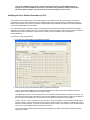
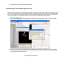
C-Motion Online Documentation
Visual3D : Tutorial : Force Platforms
Force Platform Data (# 1331)
Force Platforms provide critical data for biomechanical analysis because they measure the interaction between the subject
and the environment. If the subject is in contact with the floor, the joint forces, moments and powers have no physical
meaning unless the reaction force data are included in the analysis.
NOTE: The Analog signals that are collected from the force platform are NOT the force signals. The force signals
must be computed from these Analog signals using several parameters that specify the type of computations
required (different force platforms require different computations).
For more information see the Online Documentation
Graphing a Force Platform Signal (# 1332)
1. If the graph area at the right is still occupied, right-click anywhere on the graph area and select Remove all graphs.
2. In the Data Tree, select the ANALOG folder, then ORIGINAL. Right-click FZ1, select Graph Z, and New Graph. This
will open a graph of the Fz ANALOG channel of force platform1.
3. In the Data Tree select the GRFORCE folder, FP1, Z-component, and New Graph. This will open a graph of
Z-component of the Ground Reaction Force signal.
Note that the two signals are related to each other, but they are not identical. The ANALOG signal is stored in
the coordinate system of the force platform. The GRFORCE signal is stored in the Laboratory (Motion
Capture) Coordinate System.
NOTE: We often get questions from users claiming that the ANALOG signals for the force platform
exist, but the GRFORCE signal is zero. Check to see that the Fz Channel of the ANALOG signals is
negative. If not, then the ANALOG scale factor in the C3D file has probably been stored incorrectly by
the motion capture software. The scale factor will need to be changed; see later section.
Modifying the Force Platform Parameters (# 1333)
Force Platform data are perhaps the most confusing aspects of the C3D file format. All of the required Force Platform
parameters for the type of Force Platform must be defined correctly. Some of the parameters are specified by the Force
Platform manufacturer; these values are provided in the Manufacturers User Manual. Note that some of these parameters
can not be transferred directly in the C3D file.
The C3D format assumes consistency between units throughout the file. If the Motion Capture data has been collected in
millimeters, ALL distance measures in the file must be consistent. This means that the corner locations, and Force Platform
ORIGIN values must be in millimeters, and the moment channels of the force platform must be expressed in
Newton-millimeters.
To examine or modify the parameters.
1. In the File menu, select Modify Force Platform Parameters.
2. Click on the Get Current C3D Parameters button to populate the dialog box.
The Force Platform Zero Baseline Interval indicates that the first 10 frames of data will be averaged to define a
baseline, which is then subtracted from every frame of data..
The ORIGIN (mm) shows a –21 mm Z component. The manufacturer manual will show a positive z-component. The
c3d format assumes that this value will be a vector from the ORIGIN to the center of the top surface of the platform in
the force platform coordinate system, which means that the value in the C3D file should be negative.
Corner 1, Corner 2, Corner 3 and Corner 4 are the locations of the force platform corners specified in the laboratory
coordinate system. This information is used to transform the signals from the force platform coordinate system to the
laboratory coordinate system. In principle the force platform can be located in any orientation in the 3D data collection
volume; e.g. the force platform does not have to be on the floor..
The Analog Channels column shows the analog channel assignment number in the order the ANALOG channels
appear in the c3d file.
3. Click Done or Cancel when finished examining data.
Thresholding the Force Platform Signals (# 1334)
When force platform data exists, Visual3D attempts to assign the signal to a segment that comes into contact with it. If there
is a low level of background noise in the signal, it will appear that something must be in contact with the force platform at all
times. To ensure that only “sensible/real” contacts are used, a threshold values is specified such that any ground reaction
force signal below this value is assumed to be zero. This ensures clean contacts with the force platform.
1. Select the Properties menu.
2. Click on the Modify Minimum Force Platform Value. A dialog box will open to allow you to set a higher (or lower)
threshold than the default.
3. You can also choose one of the other options for modifying force platforms. Select Modify FP Center of Pressure
4.
Distance to Segment to specify a minimum distance (.2m default). This option allows you to verify that a particular
signal has been caused by a segment.
Copyright © 2002-2004 C-Motion, Inc.