1
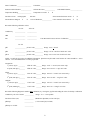
Professional Plus
Calibration Tips
Table of Contents
Introduction...................................................................................................................................1
Calibration Worksheet ..................................................................................................................1
Temperature .................................................................................................................................3
Calibration Tips .........................................................................................................................3
Troubleshooting Tips.................................................................................................................3
Conductivity ..................................................................................................................................4
Calibration Tips .........................................................................................................................4
Troubleshooting Tips.................................................................................................................4
pH .................................................................................................................................................6
Calibration Tips .........................................................................................................................6
Troubleshooting Tips.................................................................................................................6
ORP..............................................................................................................................................9
Calibration Tips .........................................................................................................................9
Troubleshooting Tips.................................................................................................................9
Dissolved Oxygen.......................................................................................................................11
Calibration Tips .......................................................................................................................11
Troubleshooting Tips...............................................................................................................12
Ammonium .................................................................................................................................15
Calibration Tips .......................................................................................................................15
Troubleshooting Tips...............................................................................................................16
Nitrate .........................................................................................................................................18
Calibration Tips .......................................................................................................................18
TroubleShooting Tips ..............................................................................................................19
Chloride ......................................................................................................................................21
Calibration Tips .......................................................................................................................21
Troubleshooting Tips...............................................................................................................22
Installing and Uninstalling Sensors .............................................................................................24
General Precautions ...............................................................................................................24
Uninstalling DO, pH, ORP, pH/ORP and ISE Sensors............................................................25
Installing DO, pH, ORP, pH/ORP and ISE Sensors ................................................................25
Uninstalling a Conductivity/Temperature Sensor in a Quatro Cable .......................................25
Installing a Conductivity/Temperature Sensor in a Quatro Cable............................................25
Cleaning a Sensor Port...............................................................................................................26
Verifying Sensor Accuracy and Calibration.................................................................................26
Resetting a Sensor to Factory Default ........................................................................................26
Introduction
This guide provides helpful instructions, tips and troubleshooting suggestions for calibrating a Professional Plus
instrument. For more detailed information on calibration and information on how to setup and operate a Pro Plus,
please refer to the Pro Plus User Manual.
Calibration Worksheet
The Calibration Worksheet on the following page is provided for your convenience. Utilizing the Calibration
Worksheet can help document your calibration and track the performance of your sensors.
1
Date of Calibration: ___________________
Technician: _____________________________________
Instrument Serial Number:______________
Software Revision:______________
Temperature Reading__________________
Temperature Accurate: Y
DO Sensor in use:
Polarographic
DO membrane changed?
Y
N
Galvanic
N
Cable Model Number:________________
Sensor notated in Sensor menu? Y
Color of Membrane_____________ Color notated in Sensor menu?
Y
N
N
Record the following calibration values:
Pre Cal
After Cal
Conductivity
______________
_____________
ORP
______________
_____________
DO
______________
_____________
True Barometric Pressure at time of calibration ___________________
Pre Cal
pH 7
______________ pH mV value___________
Range 0 mV + 50 mV
pH 4
______________ pH mV value___________
Range +165 to +180 from 7 buffer mV value
pH 10
______________ pH mV value___________
Range -165 to -180 from 7 buffer mV value
NOTE: See pH Cal tips section for additional information. Span between pH 4 and 7 and 7 and 10 mV values should be ≈ 165 to
180 mV. 177 is the ideal distance or 59 mV per pH unit.
Ammonium
1st point (1 mg/L) _________
2nd point (100 mg/L)________
Nitrate
1st point (1 mg/L) __________
2nd point (100 mg/L)________
Chloride
1st point (10 mg/L) _________
2nd point (1000mg/L)________
NH4 mV value_______ Range: 0 mV +/- 20 mV (new sensor only)
NH4 mV value_______ Range: 90 to 130 mV > 1 mg/L mV value
NO3 mV value_______ Range: 200 mV +/- 20 mV (new sensor only)
NO3 mV value_______ Range: 90 to 130 mV < 1 mg/L mV value
Cl mV value _______ Range: 225 mV +/- 20 mV (new sensor only)
Cl mV value _______ Range: 80 to 130 < 10 mg/L mV value
Record the following diagnostic numbers after calibration, by viewing the .glp file and reading the values for the day’s calibration
Conductivity Cal Cell Constant ____________
Range 5.0 +/- 1.0 acceptable
DO Sensor Value (uA)
____________
(Membrane dependent, see DO Cal Tips)
pH Slope
____________
(≈ 55 to 60 mV/pH, 59 ideal)
pH Slope % of ideal
____________
2
Temperature
CALIBRATION TIPS
Before calibrating any other Pro Plus sensor, verify that the temperature sensor is reading accurately by
comparing it to a traceable thermometer or other known reference in a water bath. Temperature compensation is
used in every other sensor measurement so its accuracy should be verified and recorded each time the Pro Plus
is calibrated. Be sure to consider the specification tolerances of both the Pro Plus temperature sensor and the
thermometer when comparing the measurements.
The Pro Plus temperature sensor can not be calibrated nor should calibration be required.
TROUBLESHOOTING TIPS
If the temperature sensor is not reading accurately, ensure that it is clean and free of debris. The conductivity
cleaning brush and warm water with mild detergent can be used to scrub the temperature sensor if needed.
Alternatively, you can use a toothbrush to clean the sensor.
Quatro Cables
Quatro cables have a replaceable combination conductivity/temperature sensor (p/n 005560). All other Pro Plus
cables have integral temperature sensors. If using a Quatro cable and your temperature sensor is not reading
accurately, remove the conductivity/temperature sensor from the cable. The Pro Plus should read ----- °C without
a temperature sensor installed. If the instrument is reading any other value, the conductivity/temperature port on
the cable may be contaminated. Refer to the Cleaning the Sensor Port section of this document for information
on how to clean the port.
After cleaning the port, recheck the temperature reading. If the temperature reading is still not displaying ----- °C
without the sensor installed, there may be a problem with the cable and/or instrument. In this case, contact your
local YSI Representative or a YSI Authorized Service Center.
Other Pro Plus Cables
If your temperature sensor is not reading accurately after cleaning around the sensor, contact your local YSI
Representative or an YSI Authorized Service Center.
3
Conductivity
The conductivity calibration should be verified every day the instrument is used. However, the conductivity
sensor is very stable and may hold its calibration for several weeks.
CALIBRATION TIPS
1. It is not necessary to calibrate conductivity, specific conductance and salinity. Calibrating one of these
parameters will simultaneously calibrate the others. YSI recommends calibrating specific conductance
(temperature compensated conductivity) for greatest ease and accuracy.
2. Ensure the conductivity sensor is clean and dry before performing a specific conductance calibration.
3. Always use fresh, traceable conductivity calibration solution when calibrating the conductivity sensor.
a. The shelf life of conductivity solution is one month after being opened. This is due to potential
changes in the value of the solution caused by evaporation which can occur after opening the bottle.
Be sure to write the open date on the bottle so you know that you are using good calibration solution.
b. Never calibrate with a conductivity solution that is less than 1.0 mS/cm. You are setting the slope on
a linear device so a good strong conductivity signal will give you the best performance. Use 1.0
mS/cm for fresh water, 10 mS/cm for brackish to estuarine water and 50 mS/cm for salt water. 1.0
mS (millisiemens) = 1000 uS (microsiemens).
4. Pre-rinse the cal cup and sensors with a small amount of calibration standard or rinse standard and discard.
5. When calibrating the conductivity sensor, the calibration solution must cover the top vent holes of the
conductivity sensor. If using a Quatro cable, the top vent hole is located on the side of the combination
conductivity/temperature sensor. If using a different cable, the conductivity sensor is integral to the cable and
the sensor has two vent holes located close to the cable. Ensure the entire conductivity sensor is submerged
in the solution or the instrument will read approximately half the expected value.
6. After placing the sensor into the solution, gently move the sensor up and down to remove any air bubbles
that may be trapped in the conductivity sensor.
7. If calibrating Specific Conductance, enter the value of the conductivity solution as it is listed for 25°C. Make
sure you are entering the correct units. 1 mS = 1,000 uS.
8. If you receive a warning message stating that the calibration is questionable, do not continue with the
calibration. Instead, select ‘No’ and investigate what is causing the questionable results. If you accept a
questionable calibration, your conductivity readings (and your DO mg/L readings) will be erroneous. Typical
causes for this error message include: incorrect entries (entering 1000 uS/cm instead of 1.0 mS/cm), not
using enough solution to cover the vent holes, air bubbles trapped in the sensor, calibrating in conductivity
instead of specific conductance, dirty conductivity electrodes, and/or bad calibration solution.
9. After accepting a good calibration, navigate to the GLP file and check the conductivity cell constant for the
calibration. For highest accuracy, the cell constant should be 5.0 +/- 0.5. However, the acceptable range is 5
+/- 1.0. A cell constant outside of this range indicates that a questionable calibration was accepted.
TROUBLESHOOTING TIPS
If you get an error message during calibration, be sure that you are:
1.
2.
3.
4.
5.
Entering the correct calibration value (1 mS/cm = 1000 uS/cm).
Calibrating in Specific Conductance mode.
Using enough solution to cover the vent holes on the sensor.
Dislodging any air bubbles that could be trapped in the sensor.
Using a fresh, traceable conductivity calibration solution.
4
If you are following the above recommendations and still receiving an error message, check the conductivity
sensor to make sure it is clean. A clean conductivity sensor should read less than 3 uS/cm in dry air. If your
sensor is dry and giving you a reading higher than 3 uS/cm in air, it should be cleaned.
The conductivity calibration generates its cell constant value after calibration. The ideal cell constant is 5.0 +/-0.5
but 5.0 +/- 1.0 is acceptable. Any significant jump or change in this number from one calibration to the next
usually indicates a problem with the calibration and/or sensor. If you are sure that your calibration standard is
good and your calibration process is correct, then your sensor may need to be cleaned.
Cleaning the Conductivity Sensor
The openings that allow sample access to the conductivity electrodes should be cleaned regularly. The small
cleaning brush included in the Maintenance Kit is intended for this purpose. Dip the brush in clean water and
insert it into each hole 10 to 12 times. In the event that deposits have formed on the electrodes, it may be
necessary to use a mild detergent (laboratory grade soap or bathroom foaming tile cleaner) with the brush. Rinse
thoroughly with clean water, then check the response and accuracy of the conductivity sensor with calibration
solution.
Quatro Cables
Quatro cables have a replaceable combination conductivity/temperature sensor (p/n 5560). All other Pro Plus
cables have integral conductivity sensors. If using a Quatro cable and your conductivity sensor is not calibrating
or is reading > 3 uS/cm in dry air after being cleaned, remove the conductivity/temperature sensor from the
cable. The Pro Plus should read < 3 uS/cm for conductivity (not specific conductance) without a conductivity
sensor installed. If the instrument is reading > 3 uS/cm without a sensor installed, the conductivity/temperature
port on the cable may be contaminated. Refer to the Cleaning the Sensor Port section of this document for
information on how to clean the port.
If the conductivity measurement continues to read more than 3 uS/cm without a conductivity/temperature sensor
installed, there may be a problem with the cable and/or instrument. In this case, contact your local YSI
Representative or a YSI Authorized Service Center.
Other Pro Plus Cables
If your conductivity sensor is not calibrating or is reading > 3 uS/cm in dry air after performing a sensor cleaning,
contact your local YSI Representative or a YSI Authorized Service Center.
5
pH
The pH calibration should be verified every day the instrument is used. However, a new pH sensor may be
capable of holding its calibration for several days.
CALIBRATION TIPS
1. If using a pH sensor in a 6051010 or Quatro cable, calibrate the sensor in port 1 prior to calibrating the
sensor in port 2. The sensor in port 2 uses the reference of the sensor installed in port 1. Therefore, it is
important to verify that the port 1 sensor is working properly before calibrating the port 2 sensor. See pH
Troubleshooting Tips for additional info.
2. The pH sensor can be calibrated with up to six calibration points.
3. Calibration can be accomplished in any buffer order.
4. pH 7 buffer should be used regardless of how many calibration points you use; however, it does not have to
be the first point.
5. In most cases, a two-point calibration is all that is required (4 and 7 or 7 and 10). You can bracket the
expected in-situ pH values. Use a three-point calibration with 4, 7 and 10 if the in-situ pH values are
unknown or if you expect the in-situ values to be on both sides of the pH scale.
6. Rinse the sensors and cal cup with a small amount of pH buffer. Fill the cup so that the pH sensor tip and the
temperature sensor are submerged in buffer.
7. If necessary, highlight the Calibration Value and enter the pH value of the buffer solution. Note: The Pro
Plus has auto buffer recognition which can be set to USA (4, 7, 10) or NIST (4.01, 6.86, 9.18) buffer values in
the pH Sensor Setup menu.
8. Record the pH millivolts for each calibration point. The acceptable mV outputs for each buffer are shown
below.
pH 7 mV value = 0 mV +/- 50 mV
pH 4 mV value = +165 to +180 from 7 buffer mV value
pH 10 mV value = -165 to -180 from 7 buffer mV value
• A value of +50 or -50 mVs in buffer 7 does not indicate a bad sensor.
• The mV span between pH 4 and 7 and 7 and 10 mV values should be ≈ 165 to 180 mV. 177 is the
ideal distance. The slope can be 55 to 60 mV per pH unit with an ideal of 59 mV per pH unit.
• If the mV span between pH 4 and 7 or 7 and 10 drops below 160, clean the sensor and try to
recalibrate.
9. Wait for the pH to stabilize in the each buffer and then press enter to accept each calibration point.
10. Rinse the sensor and cal cup with a small amount of the next buffer between calibration points.
11. After pressing enter to accept your last calibration point, press cal
to complete the calibration. Otherwise
you will continue calibrating up to 6 calibration points.
12. If you receive a warning message stating that the calibration is questionable, do not continue with the
calibration. Instead, select ‘No’ and investigate what is causing the questionable results. If you accept a
questionable calibration, your pH readings will be erroneous. Typical causes for this error message include:
incorrect Sensor/Port setup in the instrument, a dirty sensor or bad buffer solution.
13. After accepting a good calibration, navigate to the GLP file and check the pH Slope and Slope % of ideal. A
good slope should be between 55 and 60 mVs while the ideal is 59 mV. If the slope drops below 53, the
sensor should be reconditioned and recalibrated.
TROUBLESHOOTING TIPS
Typical working life for pH sensors is approximately 12-24 months depending on usage, storage and
maintenance. Proper storage and maintenance generally extends the sensor’s working life.
6
Clean and recondition the sensor if a slow response in the field has been reported or if it takes more than 90
seconds to stabilize in pH buffer.
If you get an error message during a pH calibration, check the following:
1. Ensure the pH buffers are good and not expired
2. Ensure that the pH sensor is installed in the correct port of the cable and the correct ISE is enabled in the
Sensor Setup menu.
a. If using a pH or pH/ORP combo sensor in a 6051020 cable, ensure the sensor is installed in port 1.
b. If using a pH or pH/ORP combo sensor in a 60510, 6051020 or 6051030 cable, pH should be
enabled in ISE1 of the instrument’s Sensor Setup menu.
c. If using a pH sensor in a 6051010 or Quatro cable, check to see if the pH sensor is installed in port 1
or port 2. If the pH sensor is installed in port 1, enable pH in ISE1 of the Sensor Setup menu. If the
pH sensor is installed in port 2, enable pH in ISE2 of the Sensor Setup menu. Note: It is not
recommended to use a pH/ORP combo sensor in 6051010 or Quatro cables. If using a pH/ORP
combo sensor in a 6051010 or Quatro cable, ORP will not be measured or reported.
3. If using a 6051010 or Quatro cable, you must have a sensor installed in port 1 for port 2 to operate.
Additionally, ensure that the sensor installed in port 1 is in good working order. In 6051010 and Quatro
cables, the sensors installed in port 1 and port 2 use the reference from the sensor installed in port 1 only.
Therefore, if the sensor installed in port 1 is not working properly, the readings from the sensor installed in
port 2 will be erroneous. For greatest ease, install a pH sensor in port 1 of both 6051010 and Quatro cables
and your other ISE sensor in port 2.
4. If you continue to get error messages during calibration, clean and recondition the sensor.
Cleaning and Reconditioning the pH, ORP or pH/ORP Sensor
If the pH or pH/ORP sensor has been allowed to dry out or has been stored in distilled or deionized water for an
extended period of time, soak the sensor in buffer 4 overnight to try and restore functionality.
Cleaning is required whenever deposits or contaminants appear on the glass and/or platinum surfaces or when
the sensor’s response slows. The cleaning can be chemical and/or mechanical.
Removing the sensor from the cable may make cleaning easier. Initially, moisten a soft clean cloth, lens cleaning
tissue or cotton swab to remove all foreign material from the glass bulb and/or platinum button. Then use a
moistened cotton swab to carefully remove any material that may be blocking the reference electrode junction of
the sensor. CAUTION: When using a cotton swab, be careful NOT to wedge the swab between the guard and
the glass sensor. If necessary, remove cotton from the swab tip, so that the cotton can reach all parts of the
sensor tip without stress. You can also use a pipe cleaner for this cleaning if more convenient.
If good pH and/or ORP response is not restored, perform the following additional procedure:
1. Soak the sensor for 10-15 minutes in clean water containing a few drops of commercial dishwashing liquid.
2. GENTLY clean the glass bulb and platinum button by rubbing with a cotton swab soaked in the cleaning
solution.
3. Rinse the sensor in clean water, wipe with a cotton swab moistened with clean water, and then re-rinse with
clean water.
If good pH and/or ORP response is still not restored, perform the following additional procedure:
1. Soak the sensor for 30-60 minutes in one molar (1 M) hydrochloric acid (HCl). This reagent can be
purchased from most lab supply distributors. Be sure to follow the safety instructions included with the acid.
7
2. Rinse the sensor in clean water, wipe with a cotton swab moistened with clean water (not DI water), and then
re-rinse with clean water. To be certain that all traces of the acid are removed from the sensor crevices, soak
the sensor in clean tap water for about an hour with occasional stirring.
If biological contamination of the reference junction is suspected or if good response is not restored by the above
procedures, perform the following additional cleaning step:
CAUTION: Do not mix the acid from the previous step with the chlorine bleach in the following step. A toxic
gaseous product can form from the reaction between the acid and the chlorine bleach. Be certain to copiously
rinse the sink and drain system of acid after its disposal and before the disposal of chlorine bleach.
1. Soak the sensor for approximately 1 hour in a 1:1 dilution of commercially available chlorine bleach.
2. Rinse the sensor with clean water and then soak for at least 1 hour in clean tap water with occasional stirring
to remove residual bleach from the junction. (If possible, soak the sensor for a period of time longer than 1
hour in order to be certain that all traces of chlorine bleach are removed.) Then re-rinse the sensor with clean
water and retest.
Prior to reinstalling the sensor, dry the port and sensor connector with compressed air. If you suspect port
contamination, follow the instructions in the Cleaning a Sensor Port section of this document before reinstalling
the sensor.
If your pH sensor is still not calibrating after performing a sensor cleaning, contact your local YSI Representative
or a YSI Authorized Service Center.
8
ORP
The ORP calibration should be verified every day the instrument is used. However, a new ORP sensor may be
capable of holding its calibration for several days.
CALIBRATION TIPS
1. If using a pH/ORP combination sensor, calibrate pH first to ensure it is working.
2. If using an ORP sensor in a 6051010 or Quatro cable, calibrate the sensor in port 1 prior to calibrating the
sensor in port 2. The sensor in port 2 uses the reference of the sensor installed in port 1. Therefore, it is
important to verify that the port 1 sensor is working properly before calibrating the port 2 sensor. See ORP
Troubleshooting Tips for additional info.
3. Rinse the sensors and cal cup with a small amount of ORP calibration solution. Fill the cup so that the ORP
sensor tip and the temperature sensor are submerged in solution.
4. Enter the calibration value per the temperature reading. The value of ORP calibration solution is greatly
affected by temperature. The ORP solution should include a chart of solution values per temperature. If not,
contact the supplier of the ORP solution to obtain this information. The Pro Series ORP sensors use a
Ag/AgCl 3.5 M KCl reference. Be sure the value you enter is for this type of reference. If using the YSI Zobell
calibration solution, the Pro Plus will automatically determine the calibration value.
5. Wait for the readings to stabilize and then press enter to accept the calibration.
6. If you receive a warning message stating that the calibration is questionable, do not continue with the
calibration. Instead, select ‘No’ and investigate what is causing the questionable results. If you accept a
questionable calibration, your ORP readings will be erroneous. Typical causes for this error message
include: incorrect Sensor/Port setup in the instrument, a dirty sensor or bad calibration solution.
TROUBLESHOOTING TIPS
Typical working life for ORP sensors is approximately 12-24 months depending on usage, storage and
maintenance. Proper storage and maintenance generally extends the sensor’s working life.
Clean and recondition the sensor if the sensor exhibits a slow response in Zobell solution, i.e. it takes more than
90 seconds to stabilize when placed in Zobell.
If you get error messages during an ORP calibration, check the following:
1. Ensure the ORP calibration solution is good and not expired.
2. Ensure that the ORP sensor is installed in the correct port of the cable and the correct ISE is enabled in the
Sensor Setup menu.
a. If using an ORP or pH/ORP combo sensor in a 6051020 cable, ensure the sensor is installed in port
1.
b. If using an ORP sensor in a 60510, 6051020 or 6051030 cable, ORP should be enabled in ISE1 of
the instrument’s Sensor Setup menu.
c. If using a pH/ORP combo sensor in a 60510, 6051020 or 6051030 cable, ORP should be enabled in
ISE2 of the instrument’s Sensor Setup menu.
d. If using an ORP sensor in a 6051010 or Quatro cable, check to see if the ORP sensor is installed in
port 1 or port 2. If the ORP sensor is installed in port 1, enable ORP in ISE1 of the Sensor Setup
menu. If the ORP sensor is installed in port 2, enable ORP in ISE2 of the Sensor Setup menu.
5. If using a pH/ORP combo sensor in a 6051010 or Quatro cable, ORP will not be measured or reported.
6. If using a 6051010 or Quatro cable, you must have a sensor installed in port 1 for port 2 to operate.
Additionally, ensure that the sensor installed in port 1 is calibrated and in good working order. In 6051010
and Quatro cables, the sensors installed in port 1 and port 2 use the reference from the sensor installed in
9
port 1 only. Therefore, if the sensor installed in port 1 is not working properly, the readings from the sensor
installed in port 2 will be erroneous.
7. If you continue to get error messages during calibration, clean and recondition the sensor per the instructions
in the pH Troubleshooting section of this document. If you suspect port contamination, follow the instructions
in the Cleaning a Sensor Port section before reinstalling the sensor.
8. If you continue to have problems, you can check the offset of the ORP sensor by performing a factory reset
to the ORP sensor. After resetting the sensor, compare the ORP mV readings in Zobell solution to the
calibration value. The difference between values should be less than 100 mVs. If the difference is 80 mVs or
higher, consider replacing the sensor as it is nearing the end of its life span.
10
Dissolved Oxygen
The dissolved oxygen sensor should be calibrated every day the instrument is used. It is not necessary to
calibrate in both % and mg/L or ppm. Calibrating in % will simultaneously calibrate mg/L and ppm and vice versa.
CALIBRATION TIPS
1. The Pro Plus can be calibrated in air-saturated water, water-saturated air or against a Winkler Titration. You
can perform a 1 or 2 point DO calibration. A 2 point calibration includes 1 point in a zero oxygen environment
nd
and the 2 point at full saturation.
2. For both ease of use and accuracy, YSI recommends that you perform a 1 point calibration in watersaturated air.
3. Make sure that there is a good membrane with fresh electrolyte (O2 probe solution) installed on the DO
sensor. The membrane should be clean and free of wrinkles. There should not be any air bubbles present
under the membrane. Membranes should be changed regularly and generally last 2-8 weeks depending on
use and storage.
4. To perform a 1 point calibration in water-saturated air, place the sensor in a 100% humid environment. This
can be accomplished several ways:
a. For the 60520 and 6052030 cables, moisten the sponge in the gray calibration sleeve with a small
amount of clean water and place it over the sensor guard.
b. For the 6051020 and Quatro cables, place a small amount of water in the calibration/storage cup and
place it over the sensors. When screwing the calibration cup onto the sensor bulkhead, only engage
one or two threads. Do not screw the calibration cup completely onto the sensor bulkhead. The goal
is to have air exchange between inside and outside the calibration cup.
The sponge and calibration sleeve/cup should be clean since bacterial growth may consume oxygen and
interfere with the calibration. Be sure the sensor is in air, not water, and that there are not any water droplets
on the membrane or temperature sensor.
5. After entering the % calibration mode, wait approximately 5 to 15 minutes for the storage container to
become completely saturated and, if using a polarographic sensor, to allow the sensor to stabilize.
6. Salinity affects the ability of water to hold oxygen and is used by the instrument to calculate DO mg/L (ppm).
The Salinity value displayed near the top of the DO calibration screen is either the salinity correction value
entered in the Sensor menu or the Salinity value as measured by the conductivity sensor in use. If you are
using a conductivity sensor, ensure that it is calibrated and reading correctly in order to obtain accurate DO
mg/L (ppm) measurements. If you are not using a conductivity sensor, the Salinity correction value should be
the salinity of the water you will be testing. Highlight Salinity and press enter to modify this setting if
necessary. The salinity of fresh water is typically 0-0.5 ppt and seawater is typically 35 ppt.
7. After accepting the calibration, navigate to the GLP menu and record the DO sensor’s value (sensor current
in uA). The acceptable sensor currents when calibration is performed at 25°C, in a 100% saturated air
environment at 760 mmHg are:
1.25 mil PE membrane (yellow membrane): Average 6.15 uA (min. 4.31 uA, max. 8.00 uA)
2.0 mil PE membrane (blue membrane): Average 3.38 uA (min. 2.37 uA, max. 4.40 uA)
1 mil Teflon membrane: Average 16.29 uA (min. 11.40 uA, max. 21.18 uA)
8. If you receive a warning message stating that the calibration is questionable, do not continue with the
calibration. Instead, select ‘No’ and investigate what is causing the questionable results. If you accept a
questionable calibration, your DO readings will be erroneous. Typical causes of a calibration error message
include: incorrect sensor, membrane or port setup in the instrument, incorrect barometric pressure
information, a bad membrane or a sensor that needs reconditioned.
11
TROUBLESHOOTING TIPS
1. Ensure that the correct sensor type and membrane type are enabled in the Sensor Setup Menu. Galvanic
sensors have a gray probe body and Polarographic sensors have a black probe body.
2. If using a 6051020 cable, ensure that the DO sensor is installed in port 2. If using a Quatro cable, ensure that
the DO sensor is installed in the port labeled DO.
3. Ensure the Pro Plus barometer is reading accurately. The DO % Saturation calibration uses the instrument’s
barometric pressure reading for the DO % calibration. If the barometer is not reading accurately, the
calibration will be erroneous. The barometer should be reading true barometric pressure. If you suspect the
barometer reading is incorrect, calibrate the barometer and then recalibrate the DO sensor. Laboratory
barometer readings are usually “true” (uncorrected) values of air pressure and can be used “as is” for
barometer calibration. Weather service readings are usually not “true”, i.e., they are corrected to sea level,
and therefore cannot be used until they are “uncorrected”. An approximate formula for this “uncorrection” is:
True BP in mmHg = Corrected BP in mmHg – [2.5 * (Local Altitude in ft. above sea level/100)]
4. Install a new membrane with fresh electrolyte onto the DO sensor. Ensure you are using the correct
electrolyte solution. Polarographic sensors use electrolyte that is in a white labeled bottle (KCl/Na2SO4).
Galvanic sensors use electrolyte that is in a blue labeled bottle (NaCl).
5. Recondition the DO sensor and then install a new membrane.
6. If you suspect port contamination, remove the sensor and follow the instructions in the Cleaning a Sensor
Port section.
7. If you continue to have trouble calibrating the DO sensor, contact your local YSI Representative or a YSI
Authorized Service Center.
Membrane Cap Installation
The DO membrane and electrolyte solution (O2 solution) should be changed once every 2-8 weeks depending
on use and storage. In addition, the membrane and electrolyte solution should be changed if (a) bubbles are
visible under the membrane; (b) significant deposits of dried electrolyte are visible on the membrane; or (c) if the
sensor shows unstable readings or other sensor-related symptoms. To install a new membrane cap follow these
instructions:
1. Remove the sensor guard or cal cup to access the sensor tip.
2. Unscrew and remove any old membrane cap by holding the sensor when unscrewing
the membrane cap. Discard the used membrane cap.
3. Thoroughly rinse the sensor tip with distilled or DI water.
4. Fill a new membrane cap with the appropriate electrolyte solution that has been
prepared according to the directions on the bottle. Polarographic sensors use
electrolyte that is in a white labeled bottle (KCl/Na2SO4). Galvanic sensors use
electrolyte that is in a blue labeled bottle (NaCl). Be very careful not to touch
the membrane surface during this process. Lightly tap the side of the
membrane cap to release air bubbles that may be trapped.
5. Thread the membrane cap onto the sensor. It is normal for a small amount of electrolyte
to overflow.
12
Reconditioning the DO Sensor
Polarographic Sensors - Model # 605203
Due to the chemical reaction taking place under the membrane, deposits will form on the gold cathode and silver
anode. The gold cathode will begin to appear dull and the silver anode will turn dark in color. This discoloration is
normal; however, it is recommended that you remove the deposits as needed. Perform the following cleaning
procedures to remove the deposits if 1.) You have troubles calibrating the sensor or the DO readings are
unstable; and 2.) Changing a membrane does not correct the problem.
Silver Anode:
After extended use, a layer of Silver Chloride (AgCl) builds up on the silver anode reducing the sensitivity of the
sensor. The anode must be cleaned to remove this layer and restore proper performance. The cleaning can be
chemical and/or mechanical:
Chemical cleaning: Remove the membrane cap and rinse the electrodes with deionized or distilled water. Soak
the sensing electrode section of the sensor in a 14% ammonium hydroxide solution for 2 to 3 minutes or in a 3%
ammonia solution overnight for 8-12 hours (most household ammonia cleaners are typically around 3%). Rinse
heavily in cool tap water followed by a thorough rinsing with distilled or deionized water. The anode should then
be thoroughly wiped with a wet paper towel to remove the residual layer from the anode. Trapping residual
ammonia under the new membrane cap can quickly tarnish the electrode and/or give false readings.
Note: Chemical cleaning should be performed as infrequently as possible (1 or 2 times per year depending on
use). First attempt a membrane change and recalibrate. If a new membrane does not resolve the problem, then
proceed with cleaning.
After performing a chemical cleaning, perform a mechanical cleaning on both the anode and cathode.
Mechanical cleaning: In order to sand the silver anode along the shaft of the sensor, remove the membrane and
hold the sensor in a vertical position. Wet 400 grit wet/dry sand paper with a small amount of clean water then
gently wrap it around the sensor anode and twist it a few times to lightly sand the anode (the goal is to sand off
any build-up without scratching or removing layers of the anode itself). Usually, 3 to 4 twists of the sanding disk
are sufficient to remove deposits. However, in extreme cases, more sanding may be required to remove all of the
deposits.
After completing the sanding procedure, repeatedly rinse the electrode with clean water and wipe with lens
cleaning tissue to remove any grit left by the sanding disk. Thoroughly rinse the entire tip of the sensor with
distilled or deionized water and install a new membrane.
13
Gold Cathode:
For correct sensor operation, the gold cathode must be textured properly. It can become tarnished or plated with
silver after extended use. Never use chemicals or abrasives not recommended or supplied by YSI.
First dry the sensor tip completely with lens cleaning tissue. Wet 400 grit wet/dry sand paper with a small amount
of clean water and place it face up in the palm of your hand. Next, with your free hand, hold the sensor in a
vertical position, tip down. Place the sensor tip directly down on the sanding disk and twist it in a circular motion
to sand the gold cathode. The goal is to sand off any build-up and to lightly scratch the cathode to provide a
larger surface area for the electrolyte solution under the membrane. Usually, 3 to 4 twists of the sanding disk are
sufficient to remove deposits and for the gold to appear to have a matte finish. Rinse thoroughly and wipe the
gold cathode with a wet paper towel before putting on a new membrane cap.
Note: Be sure to: (1) Only use fine 400 grit wet/dry sand paper and (2) Sand as mentioned in the above
procedures. Not adhering to either of these instructions can damage the electrodes. If this procedure is
unsuccessful, as indicated by improper DO sensor performance, contact your local YSI Representative or a YSI
Authorized Service Center.
Galvanic Sensors – Model # 605202
The Galvanic dissolved oxygen sensor is continuously reducing oxygen even when the Pro Plus is turned off.
This factor allows the sensor to be used with no warm-up time as soon as the instrument is powered on.
However, because the sensor is “on” all the time, some solid from the oxidation of the zinc anode will form in the
electrolyte within 1-2 weeks of activation. The Galvanic electrolyte solution will appear milky white after use but
this will not affect the accuracy of the sensor unless there is excessive build up which may result in jumpy
readings. Otherwise, the color change is acceptable and normal as long as DO readings remain stable. The rate
of solid formation is dependent on the type of membrane installed. The formation of solids typically form more
rapidly with the 5912 (black 1 mil Teflon), less rapid with 5913 (yellow 1.25 mil PE), and least rapid with 5914
(blue 2 mil PE).
When changing the membrane, rinse the anode and cathode with distilled or deionized water and wipe with a
clean paper towel. If white deposits are evident on the anode after rinsing and wiping, remove the deposits by
sanding the anode with 400 grit wet/dry sand paper following the “Mechanical Cleaning” instructions under the
Polarographic Silver Anode maintenance section. If there are deposits on the cathode, sand the cathode with
400 grit wet/dry sand paper following the maintenance instructions listed for the Polarographic Gold Cathode.
Note: Do not perform the Polarographic chemical cleaning on a Galvanic sensor.
If this procedure is unsuccessful, as indicated by improper sensor performance, contact your local YSI
Representative or a YSI Authorized Service Center.
14
Ammonium
The ammonium sensor should be calibrated every day the instrument is used. The ammonium sensor should
only be used in fresh water (salinity < 2 ppt) and to depths of 55 feet (17 meters) of water.
Ammonia is calculated from the ammonium, temperature and pH readings. pH greatly affects the ammonia
calculation. Therefore, for highest accuracy in the ammonia calculation, be sure to use a pH sensor in
conjunction with an ammonium sensor during measurements. If a pH sensor is not in use, the instrument will
assume the sample is neutral (pH 7) for the calculation.
CALIBRATION TIPS
1. If using an ammonium sensor with either a pH or ORP sensor on a 6051010 or Quatro cable, install the pH
or ORP sensor in port 1 and the ammonium sensor in port 2.
2. If using an ammonium sensor on a 6051010 or Quatro cable, calibrate the sensor in port 1 prior to calibrating
the sensor in port 2. The sensor in port 2 uses the reference of the sensor installed in port 1. Therefore, it is
important to verify that the sensor in port 1 is working properly before calibrating the sensor in port 2. See
ammonium Troubleshooting Tips for additional information on port configuration.
3. Exposure to the high ionic content of pH buffers can cause a significant, but temporary, drift in the
ammonium sensor. Therefore, if calibrating a pH sensor, either:
a. Remove the ammonium sensor from the cable bulkhead and plug the port. After pH calibration is
complete, reinstall the ammonium sensor and proceed with its calibration with no stabilization delay.
Or,
b. Calibrate pH first, immersing both sensors in the pH buffers. After calibrating pH, place the sensors
in 100 mg/L ammonium standard and monitor the reading. Usually, the reading starts low and may
take awhile to reach a stable value. When it does, proceed with the calibration. This may take
several hours.
4. The ammonium sensor can be calibrated with up to three calibration points. For highest accuracy, perform a
two point calibration with 1 and 100 mg/L standards within 10°C of your sample temperature.
5. Rinse the sensors and cal cup with a small amount of ammonium solution (1 mg/L for the first point and 100
mg/L for the second point). Fill the cup so that the ammonium sensor tip and the temperature sensor are
submerged in solution. If using a Quatro cable or 6051030 cable, ensure that the conductivity sensor is also
submerged in the calibration solution. The salinity reading from the conductivity sensor is used in the
algorithm for the ammonium measurement.
6. After entering the calibration screen, change the calibration value if necessary.
7. If not using a conductivity sensor, enter the salinity value of the calibration standard. After calibration, change
the salinity correction value to the salinity value of the water you will be testing in the field in order to obtain
the most accurate ammonium measurement. You can change the salinity correction value in the Sensor
menu. As mentioned, the Ammonium sensor should only be used in fresh water salinity < 2 ppt). The salinity
of fresh water is typically 0 to 0.5 ppt.
8. Record the NH4 millivolts for each calibration point. The acceptable mV outputs for each calibration solution
are shown below.
NH4 1 mg/L = 0 mV +/- 20 mV (new sensor only)
NH4 100 mg/L = 90 to 130 mV > 1 mg/L mV value
• The mV span between 1 mg/L and 100 mg/L values should be ≈ 90 to 130 mV. The slope should be
45 to 65 mV per decade.
9. Wait for the ammonium and temperature readings to stabilize in each calibration solution and then press
enter to accept each calibration point.
10. Rinse the sensor and cal cup between calibration points with a small amount of the next buffer.
11. After pressing enter to accept your last calibration point, press cal
to complete the calibration. Otherwise
you will continue calibrating up to 3 calibration points.
15
12. If you receive a warning message stating that the calibration is questionable, do not continue with the
calibration. Instead, select ‘No’ and investigate what is causing the questionable results. If you accept a
questionable calibration, your ammonium and ammonia readings will be erroneous. Typical causes for this
error message include: incorrect Sensor/Port setup in the instrument, a dirty sensor or bad buffer solution.
Preparing Ammonium Calibration solution
We recommend using YSI calibration solutions whenever possible. However, qualified users can save cost by
following these recipes for 1 and 100 mg/L standards. Other concentrations can be made by altering the amount
of ammonium chloride. All other ingredient concentrations should remain unchanged. It is important to note that
some of these chemicals are hazardous and therefore, the standards should only be prepared by qualified
chemists in laboratories where proper safety precautions are possible. It is the responsibility of the user to obtain
and study the MSDS for each chemical and to follow the required instructions with regard to handling and
disposal of these materials.
+
You will need: solid Ammonium Chloride or a certified 100 mg/L NH4 -N from a supplier, Lithium Acetate
Dihydrate, concentrated hydrochloric acid, high purity water, a good quality analytical balance, a 1000 ml
volumetric flask, accurate volumetric measuring devices for 100 ml and 10 ml of solution, and a 1000 ml glass or
plastic storage vessels. (Caution: Hydrochloric acid is highly corrosive and toxic and should therefore be
handled with extreme care in a well-ventilated fume hood. The user could also add the equivalent amount
of a less-hazardous, more dilute sample of the acid if preferred.)
100 mg/L Standard: Accurately weigh 0.3817 g of ammonium chloride and transfer quantitatively into a 1000 ml
volumetric flask. Add 2.6 g of lithium acetate dihydrate to the flask. Add approximately 500 ml of distilled or
deionized water to the flask, swirl to dissolve all of the reagents and then dilute to the volumetric mark with
distilled or deionized water. Mix well by repeated inversion and then transfer the 100 mg/L standard to a storage
bottle. Add 3 drops of concentrated hydrochloric acid to the bottle, then seal and agitate to assure homogeneity.
+
Alternatively, 100 ml of certified 100 mg/L NH4 -N standard can be used in place of the solid ammonium chloride.
1 mg/L Standard: Accurately measure 10.0 ml of the above 100 mg/L standard solution into a 1000 ml
volumetric flask. Add 2.6 g of lithium acetate dihydrate to the flask. Add approximately 500 ml of distilled or
deionized water, swirl to dissolve the solid reagents and then dilute to the volumetric mark with water. Mix well by
repeated inversion and then transfer the 1 mg/L standard to a storage bottle. Add 3 drops of concentrated
hydrochloric acid to the bottle, then seal and agitate to assure homogeneity.
TROUBLESHOOTING TIPS
Typical working life for ammonium sensors is approximately 3-6 months depending on use, storage and
maintenance. Proper storage and maintenance generally extends the sensor’s working life.
If you get error messages during an ammonium calibration, check the following:
1. Ensure the ammonium solutions are good and not expired
2. Ensure that the ammonium sensor is installed in the correct port of the cable and the correct ISE is enabled
in the Sensor Setup menu.
a. If using an ammonium sensor in a 6051020 cable, ensure the sensor is installed in port 1.
b. If using an ammonium sensor in a 60510, 6051020 or 6051030 cable, ammonium should be enabled
in ISE1 in the instrument’s Sensor Setup menu.
c. If using an ammonium sensor in a 6051010 or Quatro cable, check to see if the ammonium sensor is
installed in the port 1 or port 2. If the ammonium sensor is installed in port 1, enable ammonium in
ISE1 of the Sensor Setup menu. If the ammonium sensor is installed in port 2, enable ammonium in
ISE2 of the Sensor Setup menu. Note: If using with a pH or ORP sensor, it is recommended to
install the pH or ORP sensor in port 1 and the ammonium sensor in port 2.
16
3. If using a 6051010 or Quatro cable, you must have a sensor installed in port 1 for port 2 to operate.
Additionally, ensure that the sensor installed in port 1 is in good working order. In 6051010 and Quatro
cables, the sensors installed in port 1 and port 2 use the reference from the sensor installed in port 1 only.
Therefore, if the sensor installed in port 1 is not working properly, the readings from the sensor installed in
port 2 will be erroneous as well.
4. If you continue to get error messages during calibration, clean the sensor.
5. If you continue to get error messages during calibration, soak the sensor in 100 mg/L ammonium standard
for several hours or overnight.
6. If you suspect port contamination, follow the instructions in the Cleaning a Sensor Port section.
7. If you continue to have trouble calibrating the ammonium sensor, contact your local YSI Representative or a
YSI Authorized Service Center.
Cleaning the Ammonium Sensor
The ammonium sensor uses a PVC membrane. As always, when handling a sensor, care should be taken to
avoid damaging the membrane. After extensive use, the membranes may become coated with a deposit or
scoured with fine scratches which may cause a slow or reduced response (low slope) or unstable readings.
Deposits may be removed with a fine jet of deionized water or rinsing in alcohol followed by soaking in 100 mg/L
ammonium calibration standard.
The sensor may require soaking in the high ammonium calibration solution to recover its performance. Soak in
100 mg/L for several hours or overnight.
17
Nitrate
The nitrate sensor should be calibrated every day the instrument is used. The nitrate sensor should only be used
in fresh water (salinity < 2 ppt) and to depths of 55 feet (17 meters) of water.
CALIBRATION TIPS
1. If using a nitrate sensor with either a pH or ORP sensor on a 6051010 or Quatro cable, install the pH or ORP
sensor in port 1 and the nitrate sensor in port 2.
2. If using a nitrate sensor on a 6051010 or Quatro cable, calibrate the sensor in port 1 prior to calibrating the
sensor in port 2. The sensor in port 2 uses the reference of the sensor installed in port 1. Therefore, it is
important to verify that the sensor in port 1 is working properly before calibrating the sensor in port 2. See
nitrate Troubleshooting Tips for additional information on port configuration.
3. Exposure to the high ionic content of pH buffers can cause a significant, but temporary, drift in the nitrate
sensor. Therefore, if calibrating a pH sensor, either:
a. Remove the nitrate sensor from the cable bulkhead and plug the port. After pH calibration is
complete, reinstall the nitrate sensor and proceed with its calibration with no stabilization delay.
Or
b. Calibrate pH first, immersing both sensors in the pH buffers. After calibrating pH, place the sensors
in 100 mg/L nitrate standard and monitor the reading. Usually, the reading starts low and may take
awhile to reach a stable value. When it does, proceed with the calibration. This may take several
hours.
4. The nitrate sensor can be calibrated with up to three calibration points. For highest accuracy, perform a two
point calibration with 1 and 100 mg/L standards within 10°C of your sample temperature.
5. Rinse the sensors and cal cup with a small amount of nitrate solution (1 mg/L for the first point and 100 mg/L
for the second point). Fill the cup so that the nitrate sensor tip and the temperature sensor are submerged in
solution. If using a Quatro cable or 6051030 cable, ensure that the conductivity sensor is also submerged in
the calibration solution. The salinity reading from the conductivity sensor is used in the algorithm for the
nitrate measurement.
6. After entering the calibration screen, change the calibration value if necessary.
7. If not using a conductivity sensor, enter the salinity value of the calibration standard. After calibration, change
the salinity correction value to the salinity value of the water you will be testing in the field in order to obtain
the most accurate nitrate measurement. You can change the salinity correction value in the Sensor menu.
As mentioned, the nitrate sensor should only be used in fresh water (salinity < 2 ppt). The salinity of fresh
water is typically 0 to 0.5 ppt.
8. Record the NO3 millivolts for each calibration point. The acceptable mV outputs for each calibration solution
are shown below.
NO3 1 mg/L = 200 mV +/- 20 mV (new sensor only)
NO3 100 mg/L = 90 to 130 mV < 1 mg/L mV value
• The mV span between 1 mg/L and 100 mg/L values should be ≈ 90 to 130 mV. The slope should be
-45 to -65 mV per decade.
9. Wait for the nitrate and temperature readings to stabilize in each calibration solution and then press enter to
accept each calibration point.
10. Rinse the sensor and cal cup between calibration points with a small amount of the next buffer.
11. After pressing enter to accept your last calibration point, press cal
to complete the calibration. Otherwise
you will continue calibrating up to 3 calibration points.
12. If you receive a warning message stating that the calibration is questionable, do not continue with the
calibration. Instead, select ‘No’ and investigate what is causing the questionable results. If you accept a
questionable calibration, your nitrate readings will be erroneous. Typical causes for this error message
include: incorrect Sensor/Port setup in the instrument, a dirty sensor or bad buffer solution.
18
Preparing Nitrate Calibration Solution
We recommend using YSI calibration solutions whenever possible. However, qualified users can save cost by
following these recipes for 1 and 100 mg/L nitrate standards. Other concentrations can be made by altering the
amount of potassium nitrate. All other concentrations should remain unchanged. It is important to note that some
of these chemicals are hazardous and therefore, the standards should only be prepared by qualified chemists in
laboratories where proper safety precautions are possible. It is the responsibility of the user to obtain and study
the MSDS for each chemical and to follow the required instructions with regard to handling and disposal of these
materials.
-
You will need: Solid Potassium Nitrate or a certified 1000 mg/l NO 3-N from a supplier, Magnesium Sulfate, high
purity water, good quality analytical balance, 1000 ml volumetric flask, accurate volumetric measuring devices for
100 ml, 10 ml and 1 ml of solution, and 1000 ml glass or plastic storage vessels.
100 mg/L standard: Accurately weigh 0.7222 g of anhydrous potassium nitrate and transfer quantitatively into a
1000 ml volumetric flask. Add 1.0 g of anhydrous magnesium sulfate to the flask. Add approximately 500 ml of
water to the flask, swirl to dissolve all of the reagents, and then dilute to the volumetric mark with distilled or
deionized water. Mix well by repeated inversion and then transfer the 100 mg/L standard to a storage bottle.
Rinse the flask extensively with water prior to its use in the preparation of the 1 mg/l standard. Alternatively, 100
mL of certified 1000 mg/L NO 3-N standard can be used in place of the solid potassium nitrate.
1 mg/L standard: Accurately measure 10.0 mL of the above 100 mg/L standard solution into a 1000 mL
volumetric flask. Add 1.0 g of anhydrous magnesium sulfate to the flask. Add approximately 500 mL of distilled or
deionized water, swirl to dissolve the solid reagents, and then dilute to the volumetric mark with water. Mix well
by repeated inversion and then transfer the 1 mg/L standard to a storage bottle.
Recipes are given for 1 and 100 mg/L. Other concentrations can be made by altering the amount of potassium
nitrate. All other concentrations should remain unchanged.
TROUBLESHOOTING TIPS
Typical working life for nitrate sensors is approximately 3-6 months depending on use, storage and maintenance.
Proper storage and maintenance generally extends the sensor’s working life.
If you get error messages during a nitrate calibration, check the following:
1. Ensure the nitrate solutions are good and not expired
2. Ensure that the nitrate sensor is installed in the correct port of the cable and the correct ISE is enabled in the
Sensor Setup menu.
a. If using a nitrate sensor in a 6051020 cable, ensure the sensor is installed in port 1.
b. If using a nitrate sensor in a 60510, 6051020 or 6051030 cable, nitrate should be enabled in ISE1 of
the instrument’s Sensor Setup menu.
c. If using a nitrate sensor in a 6051010 or Quatro cable, check to see if the nitrate sensor is installed in
port 1 or port 2. If the nitrate sensor is installed in port 1, enable nitrate in ISE1 of the Sensor Setup
menu. If the nitrate sensor is installed in port 2, enable nitrate in ISE2 of the Sensor Setup menu.
Note: If using with a pH or ORP sensor, it is recommended to install the pH or ORP sensor in port 1
and the nitrate sensor in port 2.
3. If using a 6051010 or Quatro cable, you must have a sensor installed in port 1 for port 2 to operate.
Additionally, ensure that the sensor installed in port 1 is in good working order. In 6051010 and Quatro
cables, the sensors installed in port 1 and port 2 use the reference from the sensor installed in port 1 only.
Therefore, if the sensor installed in port 1 is not working properly, the readings from the sensor installed in
port 2 will be erroneous as well.
19
4. If you continue to get error messages during calibration, clean the sensor.
5. If you continue to get error messages during calibration, soak the sensor in 100 mg/L nitrate standard for
several hours or overnight.
6. If you suspect port contamination, follow the instructions in the Cleaning a Sensor Port section.
7. If you continue to have trouble calibrating the nitrate sensor, contact your local YSI Representative or a YSI
Authorized Service Center.
Cleaning and Reconditioning the Nitrate Sensor
The nitrate sensor uses a PVC membrane. As always, when handling a sensor, care should be taken to avoid
damaging the membrane. After extensive use the membranes may become coated with a deposit or scoured
with fine scratches which may cause a slow or reduced response (low slope) or unstable readings. Deposits may
be removed with a fine jet of deionized water or rinsing in alcohol followed by soaking in 100 mg/L nitrate
calibration standard.
The sensor may require soaking in the high nitrate calibration solution to recover its performance. Soak in 100
mg/L for several hours or overnight.
20
Chloride
The chloride sensor should be calibrated every day the instrument is used. The chloride sensor should only be
used in fresh water (salinity < 2 ppt) and to depths of 55 feet (17 meters) of water.
CALIBRATION TIPS
1. If using a chloride sensor with either a pH or ORP sensor on a 6051010 or Quatro cable, install the pH or
ORP sensor in port 1 and the chloride sensor in port 2.
2. If using a chloride sensor on a 6051010 or Quatro cable, calibrate the sensor in port 1 prior to calibrating the
sensor in port 2. The sensor in port 2 uses the reference of the sensor installed in port 1. Therefore, it is
important to verify that the sensor in port 1 is working properly before calibrating the sensor in port 2. See
Chloride Troubleshooting Tips for additional information on port configuration.
3. Exposure to the high ionic content of pH buffers can cause a significant, but temporary, drift in the chloride
sensor. Therefore, if calibrating a pH sensor, either:
c. Remove the chloride sensor from the cable bulkhead and plug the port. After pH calibration is
complete, reinstall the chloride sensor and proceed with its calibration with no stabilization delay.
Or,
d. Calibrate pH first, immersing both sensors in the pH buffers. After calibrating pH, place the sensors
in 1,000 mg/L chloride standard and monitor the reading. Usually, the reading starts low and may
take awhile to reach a stable value. When it does, proceed with the calibration. This may take
several hours.
4. The chloride sensor can be calibrated with up to three calibration points. For highest accuracy, perform a two
point calibration with 10 and 1000 mg/L standards within 10°C of your sample temperature.
5. Rinse the sensors and cal cup with a small amount of chloride solution (10 mg/L for the first point and 1,000
mg/L for the second point). Fill the cup so that the chloride sensor tip and the temperature sensor are
submerged in solution. If using a Quatro cable or 6051030 cable, ensure that the conductivity sensor is also
submerged in the calibration solution. The salinity reading from the conductivity sensor is used in the
algorithm for the chloride measurement.
6. After entering the calibration screen, change the calibration value if necessary.
7. If not using a conductivity sensor, enter the salinity value of the calibration standard. After calibration, change
the salinity correction value to the salinity value of the water you will be testing in the field in order to obtain
the most accurate chloride measurement. You can change the salinity correction value in the Sensor menu.
As mentioned, the chloride sensor should only be used in fresh water (salinity < 2 ppt). The salinity of fresh
water is typically 0 to 0.5 ppt.
8. Record the Cl millivolts for each calibration point. The acceptable mV outputs for each calibration solution
are shown below.
Cl 10 mg/L = 225 mV +/- 20 mV (new sensor only)
Cl 1,000 mg/L = 80 to 130 mV < 10 mg/L mV value
• The mV span between 10 mg/L and 1000 mg/L values should be ≈ 80 to 130 mV. The slope should
be -40 to -65 mV per decade.
9. Wait for the chloride and temperature readings to stabilize in each calibration solution and then press enter
to accept each calibration point.
10. Rinse the sensor and cal cup between calibration points with a small amount of the next buffer.
11. After pressing enter to accept your last calibration point, press cal
to complete the calibration. Otherwise
you will continue calibrating up to 3 calibration points.
12. If you receive a warning message stating that the calibration is questionable, do not continue with the
calibration. Instead, select ‘No’ and investigate what is causing the questionable results. If you accept a
questionable calibration, your chloride readings will be erroneous. Typical causes for this error message
include: incorrect Sensor/Port setup in the instrument, a dirty sensor or bad buffer solution.
21
Preparing Chloride Calibration Solution
The following recipes are provided for preparation of 10 and 1000 mg/L chloride reagents.
It is important to note that some of the chemicals required for these solutions could be hazardous under some
conditions. It is the responsibility of the user to obtain and study the MSDS for each chemical and to follow the
required instructions with regard to handling and disposal of these chemicals.
You will need: Solid sodium chloride or a certified 1000 mg/L chloride solution from a supplier, magnesium
sulfate, high purity water, a good quality analytical balance, 1000 ml volumetric flask, an accurate 10 ml
measuring devices, and 1000 ml glass or plastic storage vessels.
1000 mg/L standard: Accurately weigh 1.655 grams of anhydrous sodium chloride and transfer into a 1000 ml
volumetric flask. Add 0.5 grams of anhydrous magnesium sulfate to the flask. Add 500 ml of distilled or deionized
water to the flask, swirl to dissolve all of the reagents, and then dilute to the volumetric mark with water. Mix well
by repeated inversion and then transfer the 1000 mg/L standard to a storage bottle. Rinse the flask extensively
with water prior to its use in the preparation of the 10 mg/L standard. Alternatively, simply add 0.5 grams of
magnesium sulfate to a liter of a 1000 mg/L chloride standard from a certified supplier.
10 mg/L standard: Accurately measure 10 ml of the above 1000 mg/L standard solution into a 1000 ml
volumetric flask. Add 0.5 grams of anhydrous magnesium sulfate to the flask. Add 500 ml of distilled or deionized
water, swirl to dissolve the solid reagents, and then dilute to the volumetric mark with water. Mix well by repeated
inversion and then transfer the 10 mg/L standard to a storage bottle.
TROUBLESHOOTING TIPS
Typical working life for chloride sensors is approximately 3-6 months depending on use, storage and
maintenance. Proper storage and maintenance generally extends the sensor’s working life.
If you get error messages during a chloride calibration, check the following:
1. Ensure the chloride solutions are good and not expired
2. Ensure that the chloride sensor is installed in the correct port of the cable and the correct ISE is enabled in
the Sensor Setup menu.
a. If using a chloride sensor in a 6051020 cable, ensure the sensor is installed in port 1.
b. If using a chloride sensor in a 60510, 6051020 or 6051030 cable, chloride should be enabled in ISE1
of the instrument’s Sensor Setup menu.
c. If using a chloride sensor in a 6051010 or Quatro cable, check to see if the chloride sensor is
installed in port 1 or port 2. If the chloride sensor is installed in port 1, enable chloride in ISE1 of the
Sensor Setup menu. If the chloride sensor is installed in port 2, enable chloride in ISE2 of the Sensor
Setup menu. Note: If using with a pH or ORP sensor, it is recommended to install the pH or ORP
sensor in port 1 and the chloride sensor in port 2.
3. If using a 6051010 or Quatro cable, you must have a sensor installed in port 1 for port 2 to operate.
Additionally, ensure that the sensor installed in port 1 is in good working order. In 6051010 and Quatro
cables, the sensors installed in port 1 and port 2 use the reference from the sensor installed in port 1 only.
Therefore, if the sensor installed in port 1 is not working properly, the readings from the sensor installed in
port 2 will be erroneous as well.
4. If you continue to get error messages during calibration, clean the sensor.
5. If you continue to get error messages during calibration, soak the sensor in 1000 mg/L chloride standard for
several hours or overnight.
6. If you suspect port contamination, follow the instructions in the Cleaning a Sensor Port section.
7. If you continue to have trouble calibrating the chloride sensor, contact your local YSI Representative or a YSI
Authorized Service Center.
22
Cleaning and Reconditioning the Chloride Sensor
The chloride sensor is considered a pellet membrane ISE. As always, when handling sensors, care should be
taken to avoid damaging the membrane. This sensor can be regenerated by washing with alcohol and/or gently
polishing with fine emery paper in a circular motion to remove any deposits or discoloration, then thoroughly
washing with deionized water to remove any debris.
The sensor may require soaking in the high chloride calibration solution to recover its performance. Soak in
1000 mg/L for several hours or overnight.
23
Installing and Uninstalling Sensors
GENERAL PRECAUTIONS
It is important that the entire sensor connector and cable connector be dry when installing, removing or replacing
sensors. This will prevent water from entering the port. Once a sensor is removed, examine the connector inside
the port. If any moisture is present, use compressed air to completely dry the connector or place directly in front
of a steady flow of fresh air. If you suspect port contamination, follow the port cleaning procedures listed under
Cleaning a Sensor Port.
Remove sensors upside down (facing the ground) to help prevent water from entering the port upon removal.
The instrument utilizes o-rings as seals to prevent water from entering the sensor ports. When the sensors are
removed, the o-rings that provide the seal should be carefully inspected for contamination (e.g. debris, grit, etc.)
and cleaned if necessary.
If no dirt or damage to the o-rings is evident, wipe the o-rings with a lint free cloth or lens cloth to remove the old
o-ring grease. Then, lightly apply new o-ring grease (provided in the maintenance kit) to the o-rings without
removing them from their groove. If there is any indication of damage, the o-ring should be replaced with an
identical o-ring. At the time of o-ring replacement, the entire o-ring assembly should be cleaned.
Do not over-grease the o-rings. The purpose of the o-ring grease it to keep the o-ring in good condition. Excess
grease may collect grit particles that can compromise the seal. Excess grease can also cause the waterproofing
capabilities of the o-ring to diminish, potentially causing leaks. If excess grease is present, remove it using a lens
cloth or lint-free cloth.
To remove the o-rings:
Use a small, flat-bladed screwdriver or similar blunt-tipped tool to remove the o-ring from its groove. Do not use a
sharp object to remove the o-rings. Using a sharp object could damage the o-ring groove which would allow
water to enter the port resulting in permanent damage to the port and sensor. Check the o-ring and the groove
for any excess grease or contamination. If contamination is evident, clean the o-ring and nearby plastic parts
with lens cleaning tissue or equivalent lint-free cloth. Alcohol can be used to clean the plastic parts, but use only
water and mild detergent on the o-ring itself. Using alcohol on o-rings may cause a loss of elasticity and may
promote cracking. Also, inspect the o-rings for nicks and imperfections.
Before re-installing the o-rings, make sure to use a clean workspace, clean hands, and avoid contact with
anything that may leave fibers on the o-ring or grooves. Even a very small amount of contamination (hair, grit,
etc.) may cause a leak.
To re-install the o-rings:
Place a small amount of o-ring grease between your thumb and index finger. Draw the o-ring through the grease
while pressing the fingers together to place a very light covering of grease to the o-ring. Place the o-ring into its
groove making sure that it does not twist or roll. Do no excessively stretch the o-ring during installation.
Use your grease-coated finger to once again lightly go over the mating surface of the o-ring.
Do not over-grease the o-rings. The excess grease may collect grit particles that can compromise the seal.
Excess grease can also cause the waterproofing capabilities of the o-ring to diminish, potentially causing leaks. If
excess grease is present, remove it using a lens cloth or lint-free cloth.
24
UNINSTALLING DO, PH, ORP, PH/ORP AND ISE SENSORS
First, ensure that the entire sensor and cable bulkhead are clean and dry. Remove sensors upside down (facing
the ground) to help prevent water from entering the port upon removal.
Simply unscrew the sensor from the cable by holding the sensor port end of the cable (bulkhead) in one hand
and the sensor in the other hand. Twist the sensor counter-clockwise to unscrew the sensor from the port.
INSTALLING DO, PH, ORP, PH/ORP AND ISE SENSORS
First, ensure both the sensor connector and sensor port on the cable are clean and dry. If any moisture is
present, use compressed air to completely dry the connector or place directly in front of a steady flow of fresh air.
If you suspect port contamination, follow the port cleaning procedures listed under Cleaning a Sensor Port.
To connect the sensor, grasp the sensor with one hand and the sensor port end of the cable (bulkhead) in the
other. Push the sensor into the connector on the cable until it is properly seated and only one o-ring is visible.
Failure to properly seat the sensor may result in damage. Twist the sensor clockwise to engage threads and
finger tighten. Do not use a tool. This connection is waterproof. Please refer to the sensor installation sheet that
is included with each sensor for detailed instructions.
UNINSTALLING A CONDUCTIVITY/TEMPERATURE SENSOR IN A QUATRO CABLE
First, ensure that the entire sensor and cable bulkhead are clean and dry. Remove sensors upside down (facing
the ground) to help prevent water from entering the port upon removal.
Remove the conductivity/temperature sensor using the installation tool to loosen the stainless steel retaining nut.
Insert the tool into one of the holes in the stainless steel retaining nut. Next, use the installation tool to turn the
stainless steel retaining nut counter-clockwise to loosen. Do not allow the sensor to be turned with the tool.
Turning the sensor with the tool will likely damage the sensor connector. Once the stainless steel retaining nut
has been completely loosened from the bulkhead, remove the sensor from the bulkhead by pulling the sensor
straight out of the port.
INSTALLING A CONDUCTIVITY/TEMPERATURE SENSOR IN A QUATRO CABLE
First, ensure both the sensor connector and sensor port on the cable are clean and dry. If any moisture is
present, use compressed air to completely dry the connector or place directly in front of a steady flow of fresh air.
If you suspect port contamination, follow the port cleaning procedures listed under Cleaning a Sensor Port.
1. Align the connectors of the sensor and the port. With connectors aligned, push the sensor in towards the
bulkhead until you feel the sensor seat in its port. You will experience some resistance as you push the
sensor inward, this is normal
2. Once you feel the sensor seat into the port, gently rotate the stainless steel sensor nut clockwise with your
fingers, do not use the tool.
3. The nut must be screwed in by hand. If the nut is difficult to turn, STOP, as this may indicate cross threading.
If you feel resistance or cross threading at any point, unscrew the nut and try again until you are able to
screw the nut down completely without feeling any resistance. Damage to your cable/sensor may occur if you
force the parts together.
4. Once completely installed, the nut will seat flat against the bulkhead. At this point, use the installation tool
that was included with the sensor to turn the nut an additional ¼ to ½ turn. Do not over tighten.
5. Please refer to the sensor installation sheet that is included with the conductivity/temperature sensor for
detailed instructions.
25
Cleaning a Sensor Port
If you suspect port contamination, you can clean the port on the cable by filling the port with Isopropyl Alcohol for
30 seconds and then dumping it out. Next, allow the port to air dry completely or blow it out with compressed air.
Installing a sensor into a port that is not completely dry is likely to cause erratic and erroneous readings.
If the connector is corroded, contact your local YSI Representative or a YSI Authorized Service Center.
Verifying Sensor Accuracy and Calibration
Sensor accuracy and calibration can be verified by immersing a sensor into calibration solution or YSI
Confidence Solution®. Compare the readings on the Pro Plus display to the value of the solution. If the readings
have drifted more than the accuracy specification of the sensor, perform a calibration before taking field
measurements.
YSI Confidence Solution can be used to check the accuracy and calibration of the conductivity, pH and ORP
sensors. However, to maintain the highest accuracy of the instrument, it should not be used to perform a
calibration.
Resetting a Sensor to Factory Default
Occasionally, it may be necessary to reset the instrument to its factory calibration default values. To reset the
calibration values, press the Cal key
, highlight Restore Default Cal and press enter. Highlight the parameter
you wish to reset to default and press enter. Next, you will be asked to confirm the operation. Highlight Yes and
press enter to confirm.
Professional Plus Calibration Tips
Rev A
December 2010
26