1
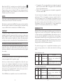
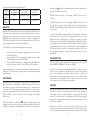
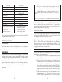
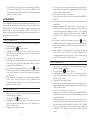
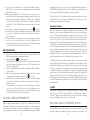
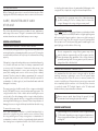
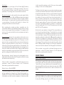
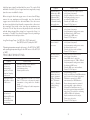
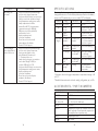
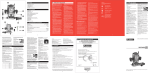
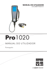
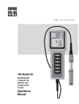
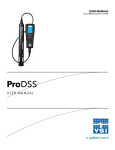
User Manual DOCUMENT #605187 Pro1020 USE R M A NUA L E ngl i s h , Fra n ça is, E spa ño l, Po rtugu ê s For Sales & Service Contact 2650 E. 40th Ave. • Denver, CO 80205 Phone 303-320-4764 • Fax 303-322-7242 1-800-833-7958 www.geotechenv.com CONTENTS Warranty................................................................................................. i Introduction..........................................................................................1 Getting Started.....................................................................................1 Initial Inspection......................................................................1 Battery Installation..................................................................1 Key Pad.....................................................................................2 Connecting the Sensor and Cable........................................3 Membrane Installation............................................................6 Run Screen...............................................................................7 Backlight..................................................................................7 Powering Off............................................................................7 Navigation...............................................................................7 First Power On.........................................................................8 System Setup Menu.............................................................................9 DO Local%.............................................................................10 Last Digit Suppression (LDS) ...............................................11 Quick DO Calibration (Quick DO Cal)................................11 Audio ....................................................................................12 Contrast..................................................................................12 DO Sensor Type....................................................................12 Membrane Type....................................................................13 DO Units................................................................................14 Item #605187 Rev A, January 2014 For the latest version of this manual, visit ysi.com ©2014 YSI Incorporated. The YSI logo is a registered trademarks of YSI Incorporated. Auto Stable............................................................................14 ISE Sensor Type.....................................................................15 ISE Units.................................................................................15 pH Buffer Set.........................................................................16 Temperature Units.................................................................16 Pressure Units........................................................................16 Language...............................................................................16 Auto Shutoff...........................................................................17 WARR ANT Y Resetting the System Setup Menu to Factory Default.......17 Calibration ..........................................................................................18 Temperature..........................................................................18 Barometer..............................................................................18 Dissolved Oxygen.................................................................19 pH Calibration.......................................................................22 ORP Calibration.....................................................................24 Taking Measurements........................................................................24 Dissolved Oxygen.................................................................25 pH/ORP...................................................................................25 Saving and Viewing Data...................................................................25 The YSI Professional 1020 instrument (Pro1020) is warranted for three (3) years from date of purchase by the end user against defects in materials and workmanship, exclusive of batteries and any damage caused by defective batteries. Pro1020 cable assemblies are warranted for two (2) years from date of purchase by the end user against defects in material and workmanship. Pro1020 Polarographic, pH and ORP sensors are warranted for one (1) year from date of purchase by the end user against defects in material and workmanship. Pro1020 Galvanic sensors are warranted for six (6) months from date of purchase by the end user against defects in material and workmanship. Pro1020 instruments & cables are warranted for one (1) year from date of purchase by the end user against defects in material and workmanship when purchased by rental agencies for rental purposes. Within the warranty period, YSI will repair or replace, at its sole discretion, free of charge, any product that YSI determines to be covered by this warranty. Sensor Maintenance.............................................................29 To exercise this warranty, call your local YSI representative, or contact YSI Customer Service in Yellow Springs, Ohio at +1 937 767-7241, 800-8974151 or visit YSI.com for a Product Return Form. Send the product and proof of purchase, transportation prepaid, to the Authorized Service Center selected by YSI. Repair or replacement will be made and the product returned, transportation prepaid. Repaired or replaced products are warranted for the balance of the original warranty period, or at least 90 days from date of repair or replacement. Sensor Storage......................................................................35 LIMITATION OF WARRANTY Saving Data............................................................................26 Viewing and Erasing Saved Data.........................................26 Care, Maintenance and Storage.......................................................28 General Maintenance...........................................................28 Troubleshooting.................................................................................36 Specifications......................................................................................39 Accessories / Part Numbers..............................................................39 Declaration of Conformity.................................................................41 Recycling.............................................................................................42 Battery Disposal....................................................................42 Contact Information...........................................................................42 Ordering and Technical Support.........................................42 Service Information...............................................................43 This Warranty does not apply to any YSI product damage or failure caused by: 1. Failure to install, operate or use the product in accordance with YSI’s written instructions; 2. Abuse or misuse of the product; 3. Failure to maintain the product in accordance with YSI’s written instructions or standard industry procedure; 4. Any improper repairs to the product; 5. Use by you of defective or improper components or parts in servicing or repairing the product; 6. Modification of the product in any way not expressly authorized by YSI. THIS WARRANTY IS IN LIEU OF ALL OTHER WARRANTIES, EXPRESSED OR IMPLIED, INCLUDING ANY WARRANTY OF MERCHANTABILITY OR FITNESS FOR A PARTICULAR PURPOSE. YSI’S LIABILITY UNDER THIS WARRANTY IS LIMITED TO REPAIR OR REPLACEMENT OF THE PRODUCT, AND THIS SHALL BE YOUR SOLE AND EXCLUSIVE REMEDY FOR ANY DEFECTIVE PRODUCT COVERED BY THIS WARRANTY. IN NO EVENT SHALL YSI BE LIABLE FOR ANY SPECIAL, INDIRECT, INCIDENTAL OR CONSEQUENTIAL DAMAGES RESULTING FROM ANY DEFECTIVE PRODUCT COVERED BY THIS WARRANTY. i INTRODUCTION T H I S PA G E L E F T I N T E N T I O N A L LY B L A N K Thank you for purchasing the YSI Pro1020, an instrument from the YSI Professional Series product family. The Pro1020 measures dissolved oxygen, temperature and either pH or ORP in water. The Pro1020 features an impact resistant and waterproof (IP-67) case, a rugged MS-8 (military-spec) cable connector, backlit display, user-selectable sensor options, 50 data set memory and a rubber over-mold case. The Pro1020 provides valuable instructions and prompts near the bottom of the display that will guide you through operation and use. G E T T I N G S TA R T E D i The Pro1020 cannot communicate to a PC via a ProComm communications saddle. INITIAL INSPECTION Carefully unpack the instrument and accessories and inspect for damage. Compare received parts with items on the packing list. If any parts or materials are damaged or missing, contact YSI Customer Service at 800-897-4151 (+1 937 767-7241) or the authorized YSI distributor from whom the instrument was purchased. BATTERY INSTALLATION The instrument requires 2 alkaline C-cell batteries. Under normal conditions, the average battery life is 425 hours at room temperature without using the back light. A battery symbol will blink in the lower, left corner of the display to indicate low batteries when approximately 1 hour of battery life remains. To install or replace the batteries: 1. Turn the instrument off and flip over to view the battery cover on the back. 2. Unscrew the four captive battery cover screws. 3. Remove the battery cover and remove the old batteries if necessary. 4. Install the new batteries, ensuring correct polarity alignment (figure 1). 5. Place the battery cover on the back of the instrument and tighten the four screws. Do not over-tighten. ii 1 Number Figure 1. Pro1020 with battery cover removed. Notice battery symbols indicating polarities. The waterproof instrument case is sealed at the factory and is not to be opened, except by factory-authorized service technicians. Do not attempt to separate the two halves of the instrument case as this may damage the instrument, break the waterproof seal, and will void the warranty. i KEY PAD Key Description 1 Calibrate Press and hold for 3 seconds to calibrate. Opens Calibrate menu from the Run screen. 2 Up Arrow Use to navigate through menus, to navigate through box options along the bottom of the Run screen and to increase numerical inputs. 3 Power and Backlight Press once to turn instrument on. Press a second time to turn backlight on. Press a third time to turn backlight off. Press and hold for 3 seconds to turn instrument off. 4 Menu Press to enter the System Setup menu from the Run screen. 5 Enter Press to confirm entries and selections. 6 Down Arrow Use to navigate through menus, to navigate through box options at the bottom of the Run screen and to decrease numerical inputs. 2 3 1 4 5 CONNECTING THE SENSOR AND CABLE 6 “Bulkhead” refers to the sensor-end of the probe/cable assembly where an ion selective electrode (ISE - either pH or ORP) and DO (galvanic or polarographic) sensor are installed (figure 3). The temperature sensor is located next to the sensor ports on the bulkhead and is not replaceable. Figure 2, Keypad 2 3 i When a port is empty on the cable, the bulkhead connector is not water-proof. Do not submerge the cable without a sensor installed! Submerging the cable without a sensor installed may cause permanent damage to the cable that is not covered under warranty. Install a YSI ProSeries port plug into the port if not installing a sensor in either port. The ISE sensor is shipped with the tip in a storage bottle. To remove, twist the bottle off the lid and remove the bottle from the sensor. Next, remove the o-ring and slide the lid off the sensor. INSTALLING THE DISSOLVED OXYGEN SENSOR i Before installing a sensor or connecting the cable to the instrument, the Sensor Type must be configured for the sensor being installed/connected. Failure to do this may result in damage not covered under warranty. The instrument will step you through this setup the first time the instrument is powered on. See the System Setup Menu section of this manual for instructions on configuring the Sensor Type after the first power on. The Pro1020 has two compatible dissolved oxygen sensors: Figure 3. The Pro1020 bulkhead sensor ports are numbered 1 and 2. Port 1 is for pH or ORP. Port 2 is for Dissolved Oxygen. INSTALLING THE ISE SENSOR The Pro1020 has three compatible ISE sensors: pH (model #1001), pHamplified (model #1001A) and ORP (model #1002). Sensor Installation: 1. Locate port 1 on the cable’s bulkhead, see figure 3. 2. If using the cable for the first time, remove the plastic plug from the cable’s bulkhead port by pulling it straight out of the port. This can be discarded. Otherwise, remove the old sensor. 3. Ensure both the sensor connector and bulkhead connector are clean and dry. 4. Grasp the sensor with one hand and the cable bulkhead in the other. 5. Push the sensor into the connector on the cable until it is firmly seated with only 1 o-ring visible. Failure to properly seat the sensor may result in damage. 6. Twist the sensor clockwise to engage the threads and finger tighten. Do NOT use a tool. This connection is water-tight. 7. If using the 1001A, install the guard extender (included in 605216 kit) onto the bulkhead prior to installing the sensor guard or calibration cup. 4 Polarographic – This sensor has a black sensor body and is engraved with the model number 2003. Polarographic will be abbreviated Polaro in the instrument’s menu. Galvanic – This sensor has a grey sensor body and is engraved with the model number 2002. For information on the differences between these two types of sensors, see Sensor Type in the System Setup Menu section of this manual. Installation: 1. Locate port 2 on the cable’s bulkhead, see figure 3. 2. If using the cable for the first time, remove the plastic plug from the cable’s bulkhead port by pulling it straight out of the port. This can be discarded. Otherwise, remove the old sensor. 3. Ensure both the sensor connector and bulkhead connector on the cable are clean and dry. 4. Grasp the sensor with one hand and the cable bulkhead in the other. 5. Push the sensor into the connector on the cable until it is firmly seated and only 1 o-ring is visible. Failure to properly seat the sensor may result in damage. 6. Twist the sensor clockwise to engage the threads and finger tighten. Do NOT use a tool. This connection is water-tight. For more detailed instructions, please refer to the sensor installation sheet that is included with each sensor. 5 CONNECTING INSTRUMENT THE PROBE/CABLE ASSEMBLY TO THE To connect the cable, align the keys on the cable connector to the slots on the instrument connector. Push together firmly and then twist the outer ring until it locks into place (figure 4). This connection is waterproof. calibrating. For detailed instructions on changing a cap membrane, see the Care, Maintenance and Storage section of this manual. RUN SCREEN Press the power/backlight key to turn the instrument on. The instrument will run through a self test and briefly display a splash screen with system information before displaying the main Run screen (figure 5). A language, dissolved oxygen sensor and membrane selection menu will display the first time the Pro1020 is powered on. See the First Power On section of this manual for more information. Figure 4, Note the keyed connector. MEMBRANE INSTALLATION The sensing end of the dissolved oxygen sensor is shipped with a protective cap that needs to be removed before using. Additionally, it is very important to install a new membrane with electrolyte solution onto the sensor after removing the cap. Prepare the electrolyte solution according to the instructions on the bottle. After mixing, allow the solution to sit for 1 hour. This will help prevent air bubbles from later developing under the membrane. Ensure you are using the correct electrolyte solution for your sensor. Galvanic sensors utilize electrolyte with a light blue label on the bottle and polarographic sensors utilize electrolyte with a white label on the bottle. The dissolved oxygen sensor is supplied with cap membranes specific to the sensor type ordered (polarographic or galvanic). 5913 and 5914 membrane kits are for Galvanic sensors and the 5908 and 5909 membrane kits are for Polarographic sensors. Remove and discard or save the protective cap from the dissolved oxygen sensor by pulling it straight off. Thoroughly rinse the sensor tip with distilled or deionized water. Fill the cap membrane 3⁄4 full of electrolyte solution, then tap the cap with a finger to release any trapped air. Be careful not to touch the membrane portion of the cap. Thread the membrane cap onto the sensor, moderately tight. Do not use a tool. It’s typical for some of the electrolyte solution to spill over. It is best to allow the new cap to remain on the sensor overnight before 6 Figure 5, Run screen. BACKLIGHT Once the instrument is powered on, pressing the power/backlight key will turn on the display backlight. The backlight will remain on until the key is pressed again or after two minutes of not pressing any key on the keypad. POWERING OFF To turn the instrument off, press and hold the power/backlight key for three seconds. NAVIGATION The up and down arrow keys allow you to navigate through the functions of the Pro1020. 7 NAVIGATING THE RUN SCREEN When in the Run screen, the up and down arrow keys will move the highlighted box along the bottom options. Once a box is highlighted, press enter to access the highlighted option. Description of Run screen box functions from left to right: Option Description Barometer Highlight and press enter to calibrate the instrument’s internal barometer. Salinity Value Highlight and press enter to adjust the salinity compensation value that is used for the dissolved oxygen mg/L measurement. Highlight and press enter to save displayed data to memory. Select Sensor Type: Polaro (black) Galvanic (grey) SAVE Highlight and press enter to view and/or erase saved data. DATA NAVIGATING THE SYSTEM SETUP MENU When in the System Setup menu, the up and down arrow keys will move the highlighted bar up and down the system setup options. See the System Setup menu section of this manual for more information about these options. FIRST POWER ON The instrument will step through an initial configuration when powered on for the first time. This will set the language, dissolved oxygen sensor type and membrane type. Use the up or down arrow keys to highlight the appropriate language, sensor and membrane, then press enter to confirm (figure 6). The Sensor Type must be configured for the dissolved oxygen sensor installed on the cable. Failure to do this may result in damage not covered under warranty. If an incorrect option is selected, it may be changed in the System Setup menu. 8 Select Membrane Type: Use to select sensor type Press to confirm 1.25 (Yellow) 2.0 (Blue) Use to select membrane Press to confirm Figure 6, Select language, dissolved oxygen sensor and membrane. After selecting a language, sensor and membrane, the Run screen will be displayed. The next time the instrument is powered up, the Run screen will display immediately after the splash screen. If the sensor type or membrane type is changed, ensure that it is updated in the System Setup menu. SYSTEM SETUP MENU Press the menu key to access the System Setup menu. The System Setup menu contains three screens notated as ‘pages’. The current page is indicated near the bottom of the display (figure 7). Use the up and down arrow keys to scroll through menu options and menu pages. 9 EXITING THE SYSTEM SETUP MENU To exit the System Setup menu, press the down arrow key until the ESC - Exit box is highlighted, then press enter to return to the Run screen. When DO Local% is enabled, the Pro1020 corrects for barometric pressure for each DO measurement instead of during calibration. Example: Instrument #1 with DO Local% enabled: At 737 mmHg barometric pressure, roughly 841 ft above sea level, the instrument would calibrate to 100%. When taking measurements at the same location (737 mmHg) in a 20°C fresh water sample that is completely air-saturated, the instrument would read: DO %L value = 100% DO mg/L value = 8.81 mg/L (9.091 x .96972) Instrument #2 DO Local% disabled: At 737 mmHg barometric pressure, roughly 841 ft above sea level, the instrument would calibrate to 737/760 x 100% = 96.97% Figure 7, page 1 of System Setup menu. DO Local% is enabled. DO LOCAL% DO Local% can be enabled or disabled by using the up or down arrow keys to highlight it and then pressing enter DO Local% indicates it is enabled, figure 7. . An ‘X’ in the box next to When taking measurements at the same location (737 mmHg) in a 20°C fresh water sample that is completely air-saturated, the instrument would read: DO% value = 96.97% DO mg/L value = 8.81 mg/L (9.091 x .96972) Hence, the mg/L readings are unaffected by DO Local%. When DO Local% is enabled, DO% values will be expressed as %L on the Run screen. 1.) Value from oxygen solubility table (Appendix B). 2.) 737/760 x 100%, correction for barometric pressure. DO Local% allows for localized % saturation measurements, but does not affect the mg/L readings. When enabled, the DO%L calibration value is always 100% regardless of the altitude or barometric pressure of the location. This deviates from YSI’s traditional method of expressing DO% saturation where the % calibration value decreases with a decrease in barometric pressure, i.e. an increase in altitude (See appendix A). To determine the % calibration value when DO Local% is disabled, divide the local, true barometric pressure in mmHg by 760 and then multiply by 100. LAST DIGIT SUPPRESSION (LDS) Example: 750/760 = 0.9868 x 100 = 98.68% calibration value when DO Local is disabled. Quick DO Cal can be enabled or disabled by using the up or down arrow keys to highlight Quick DO Cal and pressing enter. An ‘X’ in the box next to Quick DO Cal indicates it is enabled. 10 11 Last Digit Suppression (LDS) can be enabled or disabled by using the up or down arrow keys to highlight it and pressing enter . An ‘X’ in the box next to LDS indicates it is enabled. LDS rounds the DO value to the nearest tenth; i.e. 8.25 mg/L becomes 8.3 mg/L. LDS is automatically disabled during calibrations. QUICK DO CALIBRATION (QUICK DO CAL) When Quick DO Cal is enabled, press and hold the calibration key for 3 seconds while in the Run screen. Next, highlight Dissolved Oxygen and press enter to calibrate the DO sensor to the instrument’s barometer reading. For more information on Quick DO Cal, see the Calibration section of this manual. AUDIO Audio can be enabled by highlighting Audio and pressing enter. When enabled, there will be an ‘X’ in the box next to Audio. When Audio is enabled, the Pro1020 will beep twice to indicate stability when Auto Stable is enabled. The instrument will also beep when a key is pressed. When Audio is disabled, the Pro1020 will not beep. CONTRAST To adjust the display Contrast, use the up or down arrow keys to highlight Contrast, then press enter. Next, use the up or down arrow keys to adjust the contrast. The up arrow key will darken the contrast and the down arrow key will lighten the contrast. After adjusting the contrast, press enter to save and exit the Contrast adjustment function. ALTERNATE CONTRAST ADJUSTMENT OPTION If necessary, there is an alternate method of adjusting the contrast. To adjust the contrast, press and hold the menu key, then press the up arrow key to darken the contrast or press the down arrow key to lighten the contrast. DO SENSOR TYPE • • Polarographic – This sensor has a black sensor body and is engraved with the model number 2003. Polarographic will be abbreviated Polaro in the instrument menu. Galvanic – This sensor has a grey sensor body and is engraved with the model number 2002. In terms of physical configuration, membrane material and general performance, YSI Pro Series galvanic sensors are exactly like the Pro Series polarographic sensors. The advantage of using galvanic sensors is convenience. Galvanic sensors provide an instant-on sensor without the need for warm-up time but this affects the life of the sensor. Polarographic sensors last longer and have a longer warranty but require a 5-15 minute warm-up time before use or calibration. MEMBRANE TYPE Membrane Type sets the type of membrane used on the dissolved oxygen sensor; either 1.25 PE (Yellow) or 2.0 PE (blue). Use the up or down arrow keys to highlight Membrane Type and press enter to open the submenu. Highlight the membrane type corresponding to the membrane installed on the sensor and press enter to confirm. The enabled membrane type will have an ‘X’ in the box next to it. Use the down arrow key to highlight the ESC – Exit box and press enter to save changes and to close the membrane submenu. The dissolved oxygen sensor is supplied with membranes specific to the sensor type and are color coded as described in the following tables. Galvanic Membrane Kits: Model DO Sensor Type sets the type of dissolved oxygen sensor being used; either polarographic (black) or galvanic (grey). 5913 Use the up or down arrow keys to highlight Sensor Type, then press enter to open a submenu. Highlight the sensor type corresponding to the sensor installed on the cable and press enter to confirm. The enabled sensor type will have an ‘X’ in the box next to it. Next, use the down arrow key to highlight the ESC – Exit box, then press enter to save changes and to close the sensor submenu. 5914 Material Description Yellow 1.25 mil Faster response time and less flow polyethylene (PE) dependence than traditional FEP membranes. Blue 2.0 mil Less flow dependence than 1.25 mil polyethylene (PE) membrane but little slower response. Polarographic Membrane Kits: Item Color 5908 Yellow 1.25 mil Faster response time and less flow polyethylene (PE) dependence than traditional FEP membranes. The Pro1020 has two compatible sensors for use with a field cable: 5909 12 Color Blue Material Description 2.0 mil Less flow dependence than 1.25 mil polyethylene (PE) membrane but a little slower response. 13 Selecting a Dissolved Oxygen Membrane: Membrane Type Flow Dependence After 4 Minutes Required Sample Movement Typical Response Time (T-95) 5913, 5908 Yellow 25% 6 inches/second 8 seconds 5914, 5909 Blue 18% 3 inches/second 17 seconds DO UNITS Highlight DO Units and press enter to open a submenu that allows you to select the dissolved oxygen units to be displayed on the Run screen. Highlight a unit and press enter to enable or disable it. An enabled dissolved oxygen unit will have an ‘X’ in the box next to it. Highlight the ESC-Exit box along the bottom of the display and press enter to save any changes and to close the DO units submenu. There are three options for displaying dissolved oxygen: • • • mg/L will show DO readings in milligrams per liter on a scale from 0 to 50 mg/L. ppm (parts per million) is equivalent to mg/L and will show the DO reading on a scale from 0 to 50 ppm. % will show DO readings in a % saturation from 0 to 500%. This value will be expressed as %L when DO Local% is enabled. mg/L and ppm cannot be enabled and therefore displayed at the same time. DO% and mg/L or ppm can be enabled and displayed simultaneously. AUTO STABLE Auto Stable utilizes preset values to indicate when a reading is stable. The preset values are adjustable in the System Setup menu. The user can input a % change in measurement reading over ‘x’ amount of time in seconds (3 - 19). There are two separate Auto Stable controls, one for dissolved oxygen readings (DO Auto Stable) and one for ISE readings (ISE Auto Stable). They are located on the second page of the System Setup menu. When Auto Stable is enabled, an AS symbol will display next to the reading on the Run screen and blink during stabilization. When the ISE and/or conductivity reading stabilizes based on the Auto Stable 14 settings, the AS symbol will display steadily and the instrument will beep twice if Audio is turned on. DO Auto Stable can be set to a % change of 0.0 to 1.9% over 3 to 19 seconds. ISE Auto Stable can be set to a % change of 0.0 to 9.9% over 3 to 19 seconds. The auto stable criteria is applied to the pH measurement or the ORP mV reading depending on which sensor is enabled in the ISE Sensor menu. To enable Auto Stable, highlight either DO Auto Stable or ISE Auto Stable, then press enter to open the submenu. Next, use the up or down arrow keys to highlight the % change or seconds (secs) input field, then press enter to make the highlighted field adjustable. Use the up or down arrow keys to adjust the selected value, then press enter to confirm changes. Once you have confirmed any changes, highlight the ESC-Exit box along the bottom of the display and press enter to close the Auto Stable submenu. To disable Auto Stable, set the % Change input to 0.0. ISE SENSOR TYPE ISE Sensor Type sets the type of ISE sensor being used; either pH (model #1001 or #1001A) or ORP (model #1002). Use the up or down arrow keys to highlight ISE Sensor Type, then press enter to open a submenu. Highlight the sensor type corresponding to the sensor installed on the cable and press enter to confirm. The enabled sensor type will have an ‘X’ in the box next to it. Next, use the down arrow key to highlight the ESC – Exit box, then press enter to save changes and to close the sensor submenu. ISE UNITS Highlight ISE Units and press enter to open a submenu that allows you to select the ISE units to be displayed on the Run screen. Highlight a unit and press enter to enable or disable it. An enabled ISE unit will have an ‘X’ in the box next to it. Highlight the ESC-Exit box along the bottom of the display and press enter to save any changes and to close the ISE Units submenu. When pH is enabled in the ISE Sensor Type menu, there are two selectable measurement units: pH and pH mV. pH mV is the sensor’s electrical measurement signal before being converted into pH units. pH 15 mVs can help you determine if you are performing a good calibration and the condition of the pH electrode. box and press enter to save any changes and to close the Language submenu. When ORP is enabled in the ISE Sensor Type menu, only ORP mVs can be enabled as the ISE unit. The text in the boxes along the bottom of the Run screen will always be displayed in English regardless of the language enabled in the System Setup menu. pH BUFFER SET Highlight pH Buffer Set and press enter to open a submenu that allows you to select the Buffer Set used for auto buffer recognition during a pH calibration. There are two buffer set options: USA (4, 7 and 10) and NIST (4.01, 6.86 and 9.18). Highlight the buffer set and press enter to enable. The enabled buffer set will have an ‘X’ in the box next to it. Highlight the ESC-Exit box and press enter to save any changes and to close the submenu. TEMPERATURE UNITS Highlight Temperature Units and press enter to open a submenu that allows you to change the temperature units displayed on the Run screen. Highlight the desired unit (Celsius or Fahrenheit) and press enter to enable. The enabled temperature unit will have an ‘X’ in the box next to it. Only one unit may be enabled at a time. Highlight the ESC-Exit box and press enter to save any changes and to close the Temperature Units submenu. PRESSURE UNITS Highlight Pressure Units and press enter to open a submenu that allows you to change the barometric pressure units displayed on the Run screen. Highlight the desired unit (mmHg, inHg, mbar, psi, or kPa) and press enter to enable. The enabled pressure unit will have an ‘X’ in the box next to it. Only one unit may be enabled at a time. Highlight the ESC-Exit box and press enter to save any changes and to close the Pressure Units submenu. LANGUAGE Highlight Language and press enter to open a submenu that allows you to change the language. Highlight the desired language (English, Spanish, Portuguese, or French) and press enter to enable. The enabled language will have an ‘X’ in the box next to it. Highlight the ESC-Exit AUTO SHUTOFF Auto Shutoff allows you to set the instrument to turn off automatically after a period of time after the last button press. In the setup menu, use the up or down arrow keys to highlight Auto Shutoff, then press enter to open the submenu. Press enter while the minute field is highlighted to make it adjustable. Next, use the up or down arrow keys to adjust the shut off time from 0 to 60 minutes. Press enter to save the new shutoff time. Next, highlight the ESC-Exit box and press enter to close the submenu. To disable Auto Shutoff, set the Time in Minutes to 0 (zero). RESETTING THE SYSTEM SETUP MENU TO FACTORY DEFAULT To reset the Pro1020 settings back to factory default, press the down arrow key while in the System Setup menu until the Reset box is highlighted, then press enter. The instrument will prompt you to confirm the reset. Highlight Yes and press enter to continue with the reset or highlight No and press enter to cancel the reset. A Factory Reset will not affect data saved in the instrument’s memory. The following will be set in the Pro1020 after performing a reset: Parameter Reset Defaults DO Local% Off LDS (Last Digit Suppression) Off Quick DO Cal Off Audio On Contrast Set to mid range Dissolved Oxygen Sensor Type Last Setting Confirmed Dissolved Type Last Setting Confirmed Oxygen Membrane Dissolved Oxygen Units mg/L and % Dissolved Oxygen Auto Stable 16 Off (0.0 % Change and 10 seconds) 17 Parameter Reset Defaults ISE Sensor Type pH ISE Units pH ISE Auto Stable Off (0.0 % Change and 10 seconds) pH Buffer Set USA Temperature Units °C Pressure Units mmHg Language English Auto Shutoff 30 minutes Dissolved Oxygen Calibration Reset to 100% for enabled membrane and sensor* ISE Calibration Reset to factory default* Barometer Calibration Reset to factory default* *It is recommended to perform a barometer, dissolved oxygen and ISE calibration after performing a reset. C A L I B R AT I O N TEMPERATURE All Pro1020 cables have built-in temperature sensors. Temperature calibration is not required nor is it available. BAROMETER The barometer in the Pro1020 is calibrated at the factory. The barometer reading must be accurate to ensure accurate DO% calibrations and readings. If the barometer requires an adjustment, use the up or down arrow keys to highlight the barometer box along the bottom of the Run screen, then press enter. Next, use the up or down arrow keys to adjust the barometer reading to the local, true barometric pressure. Continually depress the up or down arrow key to change the barometer value more rapidly. Press enter to confirm and save the barometer adjustment. 18 i Do not use a barometer value that is corrected to sea level. Laboratory barometer readings are usually “true” (uncorrected) values of air pressure and can be used “as is” for barometer calibration. Weather service readings are usually not “true”, i.e., they are corrected to sea level, and therefore cannot be used until they are “uncorrected”. An approximate formula for this “uncorrection” is: True BP = [Corrected BP] – [2.5 * (Local Altitude in ft above sea level/100)] Although the Pro1020 barometer range is 400.0 to 999.9 mmHg, you can not adjust the value across the entire range. The barometer is very accurate and the instrument will not allow you to adjust the value drastically beyond what it is measuring. DISSOLVED OXYGEN The dissolved oxygen sensor can be easily calibrated with the press of two keys by enabling Quick DO Cal in the System Setup menu and following the Quick DO Calibration procedure. Ensure the barometer is reading accurately before performing a Quick DO Cal, DO% or DO Local% calibration because these calibration procedures use the barometer reading during calibration. If the barometer reading is erroneous during a calibration, the dissolved oxygen measurements will be inaccurate. QUICK DO CALIBRATION Perform this calibration procedure when Quick DO Calibration is enabled in the System Setup menu. 1. Ensure the DO sensor has a good membrane with electrolyte installed. A good membrane is free of wrinkles, tears, fouling and air bubbles. Install the sensor guard onto the probe. 2. Place a small amount of clean water in the calibration/storage cup and screw it onto the bulkhead. Do not thread it on completely. Be sure that 2 or 3 threads are disengaged to ensure the cup is vented to the atmosphere. Additionally, there should only be little bit of water at the bottom of the calibration cup. There should not be water droplets or water touching the DO membrane or temperature sensor. 3. Power the instrument on and, if using a Polarographic sensor, wait approximately 5 to 15 minutes for the storage cup to become completely saturated and for the sensor to stabilize. 19 4. 5. 6. 7. If using a Galvanic sensor, wait approximately 5 to 10 minutes for the cup to become completely saturated. The instrument’s Auto Shutoff should be disabled or set to at least 20 minutes. Ensure the barometer is reading accurately. If necessary, perform a barometer calibration. Press and hold the Calibrate key for 3 seconds. Highlight Dissolved Oxygen and press enter. The Pro1020 will indicate ‘Calibrating %DO’ on the display. The instrument will automatically calibrate the sensor to the current barometric pressure. If DO Local% is enabled, the sensor will calibrate to 100%. This may take up to 2 minutes depending on the age and condition of the sensor and membrane. You can press the Cal key at this time to cancel the calibration if needed. ‘Calibration Successful’ will display for a few seconds to indicate a successful calibration and then the instrument will return to the Run screen. If the calibration is unsuccessful, an error message will display on the screen. Press the Cal key to exit the error message and return to the Run screen. See the Troubleshooting guide for possible solutions. CALIBRATING IN PERCENT (DO%) Perform this calibration procedure when Quick DO Cal is disabled in the System Setup menu. 1. Perform steps 1-4 of the Quick DO Calibration procedure. 2. Press and hold the Calibrate key for 3 seconds. Highlight Dissolved Oxygen and press enter. Next, highlight % and press enter. 3. The Pro1020 will display the current DO% and temperature readings along with the % calibration value. The % calibration value is based on the barometer reading. 4. Wait at least 3 seconds, then, once the DO% and temperature readings are stable, press enter to complete the calibration. Or, press the Cal key to cancel the calibration. 5. ‘Calibration Successful’ will display for a few seconds to indicate a successful calibration and then the instrument will return to the Run screen. 6. If the calibration is unsuccessful, an error message will display on the screen. Press the Cal key to exit the calibration error message and return to the Run screen. See the Troubleshooting guide for possible solutions. 20 CALIBRATING IN PERCENT (DO LOCAL% ENABLED) Perform this calibration procedure when DO Local% is enabled and Quick DO Cal is disabled in the System Setup menu. 1. Perform steps 1-4 of the Quick DO Calibration procedure. 2. Press and hold the Cal key for 3 seconds. Highlight Dissolved Oxygen and press enter. 3. %Local will automatically be highlighted, press enter. The Pro1020 will display the current DO% and temperature readings along with the % calibration value. The % calibration value will always be 100% for DO Local%. 4. Wait at least 3 seconds, then, once the DO%L and temperature readings stabilize, press enter to complete the calibration. Or, press the Cal key to cancel the calibration. 5. ‘Calibration Successful’ will display for a few seconds to indicate a successful calibration and then the instrument will return to the Run screen. 6. If the calibration is unsuccessful, an error message will display on the screen. Press the Cal key to exit the calibration error message and return to the Run screen. See the Troubleshooting guide for possible solutions. CALIBRATING IN MG/L OR PPM 1. Power the instrument on and place the sensor into a sample that has been titrated to determine the dissolved oxygen concentration. The dissolved oxygen and temperature sensor should be in the sample. During the calibration, continuously stir or move the probe in the sample at a rate of at least 6 inches (15.5 cm) per second if using a yellow membrane or at least 3 inches (7.7 cm) per second if using a blue membrane. A stir plate may be helpful for this calibration procedure. 2. Allow the dissolved oxygen and temperature readings to stabilize. This may take 5 to 15 minutes, depending on the type and condition of the sensor. 3. Press the Cal key. Highlight Dissolved Oxygen and press enter. 4. Highlight mg/L or ppm depending on what is enabled in the System Setup menu and press enter. 5. Use the up and down arrow keys to adjust the mg/L (ppm) reading to the value of the titrated sample. Press enter to confirm the value and complete the calibration or press the Cal key to cancel the calibration. 6. ‘Calibration Successful’ will display for a few seconds to indicate a successful calibration and then the instrument will return to the Run screen. 21 7. If the calibration is unsuccessful, an error message will display on the screen. Press the Cal key to exit the calibration error message and return to the Run screen. See the Troubleshooting guide for possible solutions. pH CALIBRATION The Pro1020 pH sensors can be calibrated by performing a 1, 2 or 3-point calibration. At least one of the calibration points must be done with pH buffer 7 or 6.86. For auto buffer recognition to work properly with an older or dirty sensor, calibrate in buffer 7 or 6.86 first. For highest accuracy, use fresh, traceable pH buffers and ensure the sensor and calibration cup are clean. 1-POINT CALIBRATION 1. Place the sensor in pH buffer 7 or 6.86 and allow the temperature and pH readings to stabilize. 2. Press and hold Cal for three seconds. 3. Highlight pH and press enter. If pH is not listed as an option, check the System Setup menu to ensure pH is enabled in the ISE Sensor Type menu. 4. Highlight 1 point and press enter. 5. If necessary, use the up and down arrow keys to adjust the pH buffer value. Note the pH mV reading which ideally should be between -50 and +50 in buffer 7. 6. Press enter to complete the calibration or press Cal to cancel. 7. ‘Calibration Successful’ will display for a few seconds to indicate a successful calibration and then the instrument will return to the Run screen. 8. If the calibration is unsuccessful, an error message will display on the screen. Press the Cal key to exit the calibration error message and return to the Run screen. See the Troubleshooting guide for possible solutions. 2-POINT CALIBRATION 1. Place the sensor in pH buffer 7 or 6.86 and allow the temperature and pH readings to stabilize. 2. Press and hold Cal for three seconds. 3. Highlight pH and press enter. If pH is not listed as an option, check the System Setup menu to ensure pH is enabled in the ISE Sensor Type menu. 4. Highlight 2 point and press enter. 22 5. If necessary, use the up and down arrow keys to adjust the pH buffer value. Note the pH mV reading which ideally should be between -50 and +50 in buffer 7. 6. Press enter to continue to second point. 7. Rinse the sensor and place it in the second pH buffer (4/4.01 or 10/9.18). 8. If necessary, use the up and down arrow keys to adjust the pH buffer value. 9. Wait approximately 30 to 60 seconds for the pH sensor to stabilize and for the temperature reading to stabilize. Note the pH mV reading. pH mVs in buffer 4 should be +159 to 180 mV from the previous buffer 7 pH mV value. pH mVs in buffer 10 should be -159 to 180 mV from the previous buffer 7 pH mV value. 10. Press enter to complete the calibration or press Cal to cancel. 11. ‘Calibration Successful’ will display for a few seconds to indicate a successful calibration and then the instrument will return to the Run screen. 12. If the calibration is unsuccessful, an error message will display on the screen. Press the Cal key to exit the calibration error message and return to the Run screen. See the Troubleshooting section of this manual for possible solutions. 3-POINT CALIBRATION 1. Place the sensor in pH buffer 7 or 6.86 and allow the temperature and pH readings to stabilize. 2. Press and hold Cal for three seconds. 3. Highlight pH and press enter. If pH is not listed as an option, check the System Setup menu to ensure pH is enabled in the ISE Sensor Type menu. 4. Highlight 3 point and press enter. 5. If necessary, use the up and down arrow keys to adjust the pH buffer value. Note the pH mV reading which should be between -50 and +50 in buffer 7. 6. Press enter to continue to second point. 7. Rinse the sensor and place it in the second pH buffer (4/4.01 or 10/9.18). If necessary, use the up and down arrow keys to adjust the pH buffer value. 8. Wait approximately 30 to 60 seconds for the pH sensor to stabilize and for the temperature reading to stabilize. Note the pH mV reading. pH mVs in buffer 4 should be +159 to 180 mV from the previous buffer 7 pH mV value. pH mVs in buffer 10 should be -159 to 180 mV from the previous buffer 7 pH mV value. 23 9. Rinse the sensor and place it in the third pH buffer (4/4.01 or 10/9.18). If necessary, use the up and down arrow keys to adjust the pH buffer value. 10. Wait approximately 30 to 60 seconds for the pH sensor to stabilize and for the temperature reading to stabilize. Note the pH mV reading. pH mVs in buffer 4 should be +159 to 180 mV from the previous buffer 7 pH mV value. pH mVs in buffer 10 should be -159 to 180 mV from the previous buffer 7 pH mV value. 11. Press enter to complete the calibration or press Cal to cancel. 12. ‘Calibration Successful’ will display for a few seconds to indicate a successful calibration and then the instrument will return to the Run screen. 13. If the calibration is unsuccessful, an error message will display on the screen. Press the Cal key to exit the calibration error message and return to the Run screen. See the Troubleshooting section of this manual for possible solutions. ORP CALIBRATION 1. Place the clean sensor in ORP calibration solution. Wait for the ORP and temperature readings to stabilize. 2. Press and hold Cal for three seconds. 3. Highlight ORP and press enter. If ORP is not listed as an option, check the System Setup menu to ensure ORP is enabled in the ISE Sensor Type menu. 4. Use the up and down arrow keys to adjust the ORP calibration solution value. 5. Wait for the temperature reading to stabilize, then press enter to complete the calibration or press Cal to cancel. 6. ‘Calibration Successful’ will display for a few seconds to indicate a successful calibration and then the instrument will return to the Run screen. 7. If the calibration is unsuccessful, an error message will display on the screen. Press the Cal key to exit the calibration error message and return to the Run screen. See the Troubleshooting section of this manual for possible solutions. TA K I N G M E A S U R E M E N T S Before taking measurements, be sure the instrument has been calibrated to ensure the most accurate readings. Turn the instrument on and wait 5-15 minutes if using a polarographic sensor. Install the sensor guard to protect the sensors and membrane. If using the 1001A 24 amplified pH sensor, be sure to use the guard extender supplied in the 605216 amplified pH sensor kit. The extender is screwed onto the sensor bulkhead before the guard or cal up is installed. Place the probe in the sample to be measured and give the probe a quick shake to release any air bubbles. Be sure the sensors are completely submerged in the sample. Dissolved Oxygen Allow the temperature readings to stabilize. Next, stir the probe in the sample to overcome the stirring dependence of the dissolved oxygen sensor. The dissolved oxygen sensor requires at least 6 inches (16 cm) per second of water movement if using the yellow membrane and 3 inches (7.62 cm) per second of water movement if using the blue membrane. The required sample movement can be achieved by the natural flow of the stream, physically stirring the probe in the sample or a combination of the two. Once the values plateau and stabilize you may record the measurement and/or store the data set. The dissolved oxygen reading will drop over time if stirring or movement is ceased. If placing the DO sensor into a stream or fast flowing waters it is best to place it perpendicular to the flow and not facing into the flow. If using the DO sensor near an aeration device, it is helpful to make sure air bubbles do not burst on the membrane since that may cause unstable DO readings. You should be able to prevent this by pointing the sensor upwards so it’s facing the sky and twist tying, zip tying or rubber banding the bulkhead to the cable. Essentially, making a simple curve to the cable without bending the cable too tightly will allow you to place the sensor in the aerated sample while the sensor points skyward. This measurement method avoids air bubbles bursting on the DO membrane and results in more accurate dissolved oxygen measurements. pH/ORP pH and ORP readings are typically quick and accurate. However, it may take the sensors a little longer to stabilize if they become coated or fouled. To improve the response time of a sensor, follow the cleaning steps in the Maintenance section of this manual. S AV I N G A N D V I E W I N G D ATA The Pro1020 can store 50 data sets in non-volatile memory for later viewing. A data set includes the values currently on the display, i.e. 25 temperature, dissolved oxygen and two conductivity parameters. Each data point is referenced with a data set number, 01 through 50. SAVING DATA From the Run screen, use the up or down arrow keys to highlight the Save box and press enter to save the current readings. The instrument will indicate the data set is saved and display the saved data set’s number (figure 8). VIEWING DATA Once in Data mode, use the up and down arrow keys to view saved data sets in sequential order or press enter to access the bottom functions. After accessing the bottom functions, highlight the Data box and press enter to regain access to scrolling through the saved data. The data set displayed is indicated by the data set number, 01 through 50. ERASING DATA While viewing saved data, press the enter key to access the function boxes at the bottom of the display. Next, use the up or down arrow keys to highlight Erase, then press enter. The instrument will give you the option to erase one data set or all data sets (figure 10). Figure 8, data set saved. The instrument will display ‘Memory Full’ if all 50 data sets have been saved and you attempt to save another data set. VIEWING AND ERASING SAVED DATA Data mode allows you to view and erase saved data. From the Run screen, use the up or down arrow keys to highlight Data and press enter to access Data mode. Note that the function boxes at the bottom of the display are different in Data mode (figure 9). Figure 10, Erase data mode. Use the up or down arrow key to select Erase Data Set, Erase All Sets or the ESC-Exit function box, then press enter to confirm. Select ESC-Exit and press enter to exit Erase mode without erasing any data. Select Erase Data Set and press enter to erase the data set that was displayed before entering Erase mode. For example, if data set 12 was displayed before entering erase mode, and Erase Data Set is selected, Data Set 12 will be erased from memory and the data sets AFTER that number will move up to keep them sequential. For example, if there are 15 records and number 12 is erased then 13 becomes 12, 14 becomes 13, and 15 becomes 14. The instrument will return to Data mode after erasing one data set. Select Erase All Data Sets and press enter to clear the Pro1020 memory and return to Data mode. Figure 9, Data mode. 26 27 EXITING DATA MODE While in Data mode, press enter to access the bottom functions. Next, highlight the ESC-Exit box and press enter to return to the Run screen. CARE, MAINTENANCE AND STOR AGE This section describes the proper procedures for care, maintenance and storage of the sensors. The goal is to maximize their lifetime and minimize down-time associated with improper sensor usage. GENERAL MAINTENANCE GENERAL MAINTENANCE - GASKET AND O-RINGS The instrument utilizes gasket and o-ring seals to prevent water from entering the battery compartment and the sensor port. Following the recommended procedures will help keep the instrument functioning properly. If the gasket, o-rings and sealing surfaces are not maintained properly, it is possible that water can enter the battery compartment and/ or sensor port of the instrument. If water enters these areas, it can damage the battery terminals or sensor port causing loss of battery power, false readings and corrosion to the sensors, ports or battery terminals. Therefore, when the battery compartment lid is removed, the gasket that provides the seal should be carefully inspected for contamination (i.e. debris, grit, etc.) and cleaned with water and mild detergent if necessary. The same inspection should be made of the o-rings associated with the pH, ORP and DO sensor connector when replacing a sensor. The o-rings should be free of dirt or debris before installing the sensor onto the cable. If no dirt or damage to the o-rings is evident, then they should be lightly greased with the o-ring grease provided without removing them from their groove. However, if there is any indication of damage, the sensor o-ring should be replaced with an identical o-ring. To remove the sensor o-rings: Use a small, flat-bladed screwdriver or similar blunt-tipped tool to remove the o-ring from its groove near the sensor connector. Check the o-ring and the groove for any excess grease or contamination. If contamination is evident, clean the o-ring and nearby plastic parts with lens cleaning tissue or equivalent lint-free cloth. Alcohol can be used 28 to clean the plastic parts, but use only water and mild detergent on the o-ring itself. Also, inspect the o-rings for nicks and imperfections. i Using alcohol on o-rings may cause a loss of elasticity and may promote cracking. Do not use a sharp object to remove the o-rings. Damage to the o-ring or the groove may result. To re-install the sensor o-rings: Place a small amount of o-ring grease between your thumb and index finger. (More grease is not better!) Draw the o-ring through the grease while pressing the fingers together to place a very light covering of grease on the o-ring. Place the o-ring into its groove ensuring that it does not twist or roll. Use the previously grease-coated finger to once again lightly go over the surface of the o-ring. i Do not over-grease the o-rings. Excess grease may collect particles that can compromise the seal. Excess grease can also cause the waterproofing capabilities of the o-ring to diminish, potentially causing leaks. If excess grease is present, remove it using a lens cloth or lint-free cloth. GENERAL MAINTENANCE - SENSOR PORTS It is important that the entire sensor connector end be dry when installing, removing or replacing a sensor. This will prevent water from entering the port. Once the sensor is removed, examine the connector inside the port. If any moisture is present, use compressed air to completely dry the connector or let it air dry. If the connector is corroded, contact YSI Technical Support or the YSI authorized distributor where you purchased the instrument. i Remove sensors upside down (facing the ground) to help prevent water from entering the port upon removal. SENSOR MAINTENANCE i Typical working life for pH and ORP sensors is approximately 12-24 months depending on usage, storage and maintenance. Proper storage and maintenance generally extends the sensor’s working life. 29 SENSOR MAINTENANCE - TEMPERATURE from the sensor crevices, soak the sensor in clean water for about an hour with occasional stirring. You must keep the temperature sensor free of build up. No additional maintenance is required. A toothbrush can be used to scrub the temperature sensor if needed. SENSOR MAINTENANCE - pH AND ORP i CAUTION: When using a cotton swab, be careful NOT to wedge the swab between the guard and the glass sensor. If necessary, remove cotton from the swab tip, so that the cotton can reach all parts of the sensor tip without stress. You can also use a pipe cleaner for this operation if more convenient. Cleaning is required whenever deposits or contaminants appear on the glass or platinum sensor surfaces or when the sensor’s response slows. The cleaning can be chemical and/or mechanical. Removing the sensor from the cable may make cleaning easier. Initially, use clean water and a soft clean cloth, lens cleaning tissue, or cotton swab to remove all foreign material from the glass bulb or platinum button. Then use a moistened cotton swab to carefully remove any material that may be blocking the reference electrode junction of the sensor. If good pH or ORP response is not restored, perform the following additional procedure: 1. Soak the sensor for 10-15 minutes in clean water containing a few drops of commercial dish washing liquid. 2. GENTLY clean the glass bulb and platinum button by rubbing with a cotton swab soaked in the cleaning solution. 3. Rinse the sensor in clean water (not DI water), wipe with a cotton swab saturated with clean water, and then rerinse with clean water. If good pH or ORP response is still not restored, perform the following additional procedure: 1. Soak the sensor for 30-60 minutes in one molar (1 M) hydrochloric acid (HCl). This reagent can be purchased from most lab supply distributors. Be sure to follow the safety instructions included with the acid. 2. Rinse the sensor in clean water, wipe with a cotton swab saturated with clean water (not DI water), and then rerinse with clean water. To be certain that all traces of the acid are removed 30 i CAUTION: Do NOT mix the acid from the previous step with the chlorine bleach in the following step. Toxic gaseous products can be formed from the reaction between acid and chlorine bleach. Be certain to copiously rinse the sink and drain system of acid after its disposal and before disposal of the chlorine bleach. If biological contamination of the reference junction is suspected or if good response is not restored by the above procedures, perform the following additional cleaning step: 1. First, be sure all HCl acid from the previous cleaning step has been rinsed from the probe, sink and drain! 2. Soak the sensor for approximately 1 hour in a 1:1 dilution of commercially-available chlorine bleach. 3. Rinse the sensor with clean water (not DI water) and then soak for at least 1 hour in clean water with occasional stirring to remove residual bleach from the junction. (If possible, soak the sensor for a period of time longer than 1 hour in order to be certain that all traces of chlorine bleach are removed.) Then rerinse the sensor with clean water and retest. Dry the port and sensor connector with compressed air and apply a very thin coat of o-ring lubricant to all o-rings before reinstallation. If this procedure is unsuccessful, as indicated by improper sensor performance, contact YSI Technical Support or the YSI authorized dealer where you purchased the instrument. SENSOR MAINTENANCE - DISSOLVED OXYGEN Membrane Cap Installation The DO sensor (Polarographic or Galvanic) is shipped with a protective red cap that needs to be removed before using. Remove the red protective cap or used cap membrane and replace it with a new cap membrane following these instructions: Remove the sensor guard to access the sensor. 31 Remove the protective red cap by pulling it straight off the sensor. Or, unscrew and remove the used cap membrane by holding the sensor while unscrewing the cap membrane. Discard the used cap membrane. Thoroughly rinse the sensor tip with distilled or deionized water. dull, the sensor may need resurfaced using a 400 grit wet/dry sanding disc included in the membrane kit. Do not sand the electrodes every membrane change as this is not routine maintenance. In fact, visually, the anode may appear tarnished and operate properly. YSI recommends using the sanding disc if the sensor has difficulty stabilizing or calibrating after a regular membrane change. To clean and resurface the sensor, follow the instructions below. Fill a new cap membrane 3/4 full with electrolyte solution that has been prepared according to the directions on the bottle. Be very careful not to touch the membrane surface. Lightly tap the side of the cap membrane to release bubbles that may be trapped. Thread the cap membrane onto the sensor. It is normal for a small amount of electrolyte to overflow. Replace the sensor guard. Gold Cathode For correct sensor operation, the gold cathode (figure 11) must be textured properly. It can become tarnished or plated with silver after extended use. Never use chemicals or abrasives that have not been recommended or supplied by YSI. First dry the sensor tip completely with lens cleaning tissue. Wet a 400 grit sanding disc and place it face up in the palm of your hand. Next, with your free hand, hold the sensor in a vertical position, tip down. Place the sensor tip directly down on the sanding disc and twist it in a circular motion to sand the gold cathode. The goal is to sand off any build-up and to lightly scratch the cathode to provide a larger surface area for the electrolyte solution under the membrane. Usually, 3 to 4 twists of the sensor are sufficient to remove deposits and for the gold to appear to have a matte finish. Rinse the sensor thoroughly with distilled or deionized water and wipe the gold cathode with a wet paper towel before installing a new cap membrane. If the cathode remains tarnished, contact YSI Technical Support or the YSI authorized dealer where you purchased the instrument. Polarographic Sensors – Model # 605203 The cap membrane and KCl (potassium chloride) electrolyte solution should be changed every 2-4 weeks during regular use. In addition, the electrolyte solution and membrane should be changed if (a) bubbles are visible under the membrane; (b) dried electrolyte is visible on the membrane; and (c) if the sensor shows unstable readings or other sensor-related symptoms. During membrane changes, examine the gold cathode at the tip of the sensor and the silver anode along the shaft of the sensor (figure 11). If either the silver anode is black in color or the gold cathode is 32 Figure 11, DO sensor with membrane removed. 33 Silver Anode After extended use, a thick layer of Silver Chloride (AgCl) builds up on the silver anode (figure 11) reducing the sensitivity of the sensor. The anode must be cleaned to remove this layer and restore proper performance. The cleaning can be chemical and/or mechanical: Mechanical cleaning: In order to sand the silver anode, simply hold the sensor in a vertical position. Wet the 400 grit sanding disc and gently wrap it around the sensor and twist it a few times to lightly sand the anode (the goal is to simply sand off any build-up without scratching or removing layers of the anode itself). Usually, 3 to 4 twists of the sanding disc are sufficient to remove deposits. After completing the sanding procedure, repeatedly rinse the electrode with distilled or deionized water and wipe with lens cleaning tissue to remove any grit left by the sanding disc. Thoroughly rinse the entire tip of the sensor with distilled or deionized water and install a new membrane. Chemical cleaning: Remove the cap membrane and rinse the sensor with deionized or distilled water. Soak the sensing section of the sensor in a 14% ammonium hydroxide solution for 2 to 3 minutes or in a 3% ammonia solution overnight for 8-12 hours (most household ammonia cleaners are typically around 3%). Rinse heavily in cool tap water followed by a thorough rinsing with distilled or deionized water. The anode should then be thoroughly wiped with a lens cleaning tissue to remove the residual layer from the anode. Trapping residual ammonia under the new membrane cap can quickly tarnish the electrode and/or give false readings and should therefore be avoided. After performing a chemical cleaning on the polarographic sensor, lightly sand the cathode and anode following the mechanical cleaning procedures described previously. If this procedure is unsuccessful, as indicated by improper sensor performance, contact YSI Technical Support or the YSI authorized dealer where you purchased the instrument. Galvanic Sensors – Model # 605202 YSI recommends that the Sodium Chloride (NaCl) electrolyte solution and cap membrane be changed every 2-4 weeks during regular use. In addition, the electrolyte solution and membrane should be changed if (a) bubbles are visible under the membrane; (b) dried electrolyte 34 is visible around the membrane; and (c) if the sensor shows unstable readings or other sensor-related symptoms. The Galvanic dissolved oxygen sensor is continuously reducing oxygen even when the instrument is turned off. This factor allows the sensor to be used with no warm-up period as soon as the instrument is powered on. However, because the sensor is “on” all the time, some solid from the oxidation of the zinc anode will form in the electrolyte within 1-2 weeks of activation. Small amounts of the solid will generally cause no performance problems, but excessive amounts may result in jumpy dissolved oxygen readings. The rate of solid formation is dependent on the type of membrane installed. The formation of solids typically form more rapidly with 5913 (1.25 mil PE) membrane, and less rapid with 5914 (2 mil PE) membranes. At the time the cap membrane is changed, YSI recommends that you rinse the anode and cathode (figure 11) with distilled or deionized water and wipe with a lens cleaning tissue. If white deposits are evident on the anode after cleaning, YSI recommends that you remove this material by sanding the anode with the 400 grit wet/dry sanding disc included in the membrane kit following the “Mechanical Cleaning” instructions under the Polarographic Silver Anode maintenance section of this manual. If there are deposits on the cathode, sand the cathode with the 400 grit wet/dry sanding disc following the maintenance instructions listed in this manual for the Polarographic Gold Cathode. If this procedure is unsuccessful, as indicated by improper sensor performance, contact YSI Technical Support or the YSI authorized dealer where you purchased the instrument. SENSOR STORAGE SHORT TERM STORAGE The instrument is supplied with a plastic calibration/storage cup that screws onto the cable. The cup is used for short-term storage (less than 1 weeks). Be sure to keep a small amount of clean tap water in the cup during storage. With a small amount of water, the cup provides a 100% water saturated air environment which is ideal for short-term sensor storage. LONG TERM STORAGE The dissolved oxygen sensor should be stored long term in a dry state while the pH or ORP sensor should be stored in solution. When storing for more then 30 days, place the pH or ORP sensor in the storage 35 bottle that was originally included with the sensor. This can be filled with buffer 4 solution. If you no longer have the storage bottle, simply place the sensor in a buffer 4 solution. When storing the dissolved oxygen sensor for more than 30 days, remove the cap membrane and thoroughly rinse the dissolved oxygen sensor with distilled or deionized water. Once the sensor has been rinsed either blow it dry with compressed air or allow to air dry completely. Next, install a new, clean, dry cap membrane onto the sensor. This will keep the sensor dry and protect the anode and cathode during storage. After storing for a long period of time, it is necessary to “condition” the dissolved oxygen sensor by installing a new membrane with electrolyte solution. Long Term Storage Temp: -5 to 70°C (23 to 158°F) without pH 0 to 30°C (32 to 86°F) with pH or ORP* *Operating temperature range for pH sensor is -5 to 60°C (23 to 140°F) and operating temperature range for the ORP sensor is 0 to 60°C (32 to 140°F) TROUBLESHOOTING Symptom Symptom Instrument will not calibrate pH or ORP; instrument displays “Calibration Over”, “Calibration Under”, or “Unstable Reading” during calibration. 1. Low battery voltage, replace batteries. 2. Batteries installed incorrectly, check battery polarity. 3. Return system for service. Temperature values display Over or Undr on Run screen. 1. Sample temperature is less than -5° C or more than +55°C. Increase or decrease the sample temperature to bring within the allowable range. 2. Contact YSI Tech Support. Possible temperature sensor failure. Barometer reads over/undr and calibrating DO results in a Barometric Pressure Over/Undr error message. 1. Barometer failure, return system for service 36 1. Verify correct ISE sensor type selection in the System Setup menu. 2. Verify the calibration solution is accurate. 3. If calibrating pH, make sure you are calibrating buffer 7 first. 4. Clean the pH or ORP sensor. 5. Contact YSI Tech Support. pH or ORP readings 1. Verify correct ISE sensor type selection are inaccurate. in the System Setup menu. 2. Verify temperature readings are accurate. 3. Recalibrate the pH or ORP sensor. 4. Clean the pH or ORP sensor. 5. Contact YSI Tech Support. pH values display Over or Undr on Run screen. 1. Verify correct ISE sensor type selection in the System Setup menu. 2. Verify temperature readings are accurate. 3. Recalibrate the pH sensor. 4. Clean the pH sensor and recalibrate. 5. Contact YSI Tech Support. ORP values display Over or Undr on Run screen. 1. Verify correct sensor type selection in the System Setup menu. 2. Sample ORP value is outside the measurement range of -1500 to 1500 mV. 3. Verify temperature readings are accurate. 4. Recalibrate the ORP sensor. 5. Clean the ORP sensor and recalibrate. 6. Contact YSI Tech Support. Instrument will not calibrate dissolved oxygen; instrument displays “Calibration Over”, “Calibration Under”, or “Unstable Reading” during calibration. 1. Verify barometer reading. 2. Verify correct DO sensor and DO membrane type selection in the System Setup menu. 3. Calibrations cup may not be 100% water saturated, see DO Calibration. 4. Ensure adequate sample movement if performing mg/L or ppm calibration. 5. Allow sufficient stabilization time for dissolved oxygen and temperature AND wait at least 3 seconds before confirming a DO% or DO Local% calibration. 6. Replace membrane and electrolyte. 7. Clean sensor electrodes. 8. Contact YSI Tech Support. Possible Solution Instrument will not turn on, a battery symbol appears, or “Critical Shutdown” displays on the screen. Possible Solution 37 Symptom DO readings are inaccurate. Possible Solution 1. Verify correct DO sensor/membrane type selection in the System Setup menu. 2. Verify user-defined Salinity correction value. Salinity is used in the calculation of mg/L. 3. Verify temperature readings are accurate. 4. Sample temperature should be between 0 and 45 ºC, the temperature compensation range for DO mg/L. 5. DO sensor not properly calibrated, recalibrate the sensor. 6. Replace membrane and electrolyte. Recalibrate. 7. Clean sensor electrodes. Install new membrane. Recalibrate 8. Contact YSI Tech Support. Dissolved Oxygen 1. Verify correct DO sensor/membrane type values display Over or selection in the System Setup menu. Undr on Run screen. 2. If using a polarographic sensor, allow instrument to warm up for 5 – 15 minutes before use. 3. Sample dissolved oxygen concentration is more than 50 mg/L or 500%, or less than –0.02 mg/L or -0.3%. 4. Verify user-defined Salinity correction value. 5. Verify temperature readings are accurate. 6. Replace membrane and electrolyte. Recalibrate. 7. Clean sensor electrodes. Replace membrane. Recalibrate. 8. Contact YSI Tech Support. S P E C I F I C AT I O N S These specifications represent typical performance and are subject to change without notice. For the latest product specification information, please visit YSI’s website at ysi.com or contact YSI Tech Support. Parameter Temperature Range Resolution Accuracy -5 to 55°C* 0.1°C ± 0.2°C pH 0 to 14 pH units 0.01 Instrument with cable and sensor: +/- 0.2 ORP -1500 to 1500 mV 1 mV Instrument with cable and sensor: +/-20 mV 0 to 200% air saturation 1% or 0.1%, user selectable ± 2% of the reading or ± 2% air saturation, whichever is greater 200 to 500% air saturation 1% or 0.1%, user selectable ± 6% of the reading 0 to 20 mg/L 0.1 or 0.01 mg/L, user selectable ±2% of the reading or ± 0.2 mg/L, whichever is greater 20 to 50 mg/L 0.1 or 0.01 mg/L, user selectable ±6% of the reading 500 to 800 mmHg** 0.1 mmHg ±5 mmHg within 15°C of calibration temperature Dissolved Oxygen Barometer * Automatic dissolved oxygen temperature compensation range is -0 to 45 ºC **Available barometer units include: mmHg, inHg, mbars, psi, or KPa A C C E S S O R I E S / PA R T N U M B E R S Part Number 38 Description 6051020 Pro1020 Instrument 6261020-1, -4, -10, -20, or -30 1, 4, 10, 20, 30-meter cable assembly* (3.2, 13, 32.8, 65.6, 98.4-feet) 605101 pH Sensor 605216 Amplified pH Sensor kit. Includes sensor and guard extender. Guard extender required on first amplified sensor purchase only. 605323 Amplified pH Sensor 605102 ORP Sensor 39 Part Number Description 605202 Galvanic DO Sensor 605203 Polarographic Sensor 603059 Flow cell, 203 ml 603056 Flow cell mounting spike 603075 Carrying case, large, soft-sided 603162 Carrying case, small, soft-sided (holds instrument and up to a 4 meter cable/probe assembly 603074 Carrying case, hard-sided 603069 Belt clip for clipping instrument onto belt 063517 Ultra clamp for instrument for clamping instrument to lab counter or other surface 063507 Tripod for instrument 603062 Cable management kit, included with all cables longer than 1 meter 605978 Cable weight, 4.9 oz, stackable 603070 Shoulder strap 003821 pH 4 Buffer, box of 6 pints 003822 pH 7 Buffer, box of 6 pints 003823 pH 10 Buffer, box of 6 pints 603824 pH Buffer, assorted case, 2 pints each of buffer 4, 7 and 10 605306 5908 Cap membrane kit, 1.25 mil PE (6 each), includes electrolyte (yellow cap). Used with Polarographic sensor. 605307 5909 Cap membrane kit, 2 mil PE (blue cap, 6 each), includes electrolyte (blue cap). Used with Polarographic sensor. 605913 5913 Cap membrane kit, 1.25 mil PE (yellow cap, 6 each), includes electrolyte. Used with Galvanic sensor. 605914 5914 Cap membrane kit, 2 mil PE (blue cap, 6 each), includes electrolyte. Used with Galvanic sensor. *All cables include a temperature sensor. The pH or ORP and Dissolved Oxygen sensors are sold separately. 40 D E C L A R AT I O N O F C O N F O R M I T Y The undersigned hereby declares on behalf of the named manufacturer under our sole responsibility that the listed product conforms to the requirements for the listed European Council Directive(s) and carries the CE mark accordingly. Manufacturer: YSI Incorporated 1725 Brannum Lane Yellow Springs, OH 45387 USA Product Name: Pro1020 Water Quality Instrument Model Numbers Instrument/ Accessory: Pro1020 (6051020) Probe/Cable Assemblies: 6051020-1, -4, -10, -20, and -30 Conforms to the following: Directives: EMC 2004/108/EC RoHS 2011/65/EU WEEE 2012/19/EU Harmonized Standards: • • • Supplementary Information: All performance met the operation criteria as follows: 1. ESD, IEC 61000-4-2:2001 2. Radiated Immunity, IEC 61000-4-3:2006 3. Electrical Fast Transient (EFT), IEC 610004-4:2004, +Corr. 1:2006 + Corr. 2:2007 4. Radio Frequency, Continuous Conducted Immunity, IEC61000-4-6:2006 5. IEC 6100-4-8:2001 Authorized EU Representative Xylem Analytics UK Ltd Unit 2 Focal Point, Lacerta Court, Works Road Letchworth, Hertfordshire, SG6 1FJ UK EN61326-1:2006 (IEC 61326-1:2005) IEC 61000-3-2:2005 IEC 61000-3-3:2005 Signed: Lisa M. Abel Title: Director of Quality Date: 23 January 2014 41 REC YCLING YSI is committed to reducing the environmental footprint in the course of doing business. Even though materials reduction is the ultimate goal, we know there must be a concerted effort to responsibly deal with materials after they’ve served a long, productive life-cycle. YSI’s recycling program ensures that old equipment is processed in an environmentally friendly way, reducing the amount of materials going to landfills. • • • Printed Circuit Boards are sent to facilities that process and reclaim as much material for recycling as possible. Plastics enter a material recycling process and are not incinerated or sent to landfills. Batteries are removed and sent to battery recyclers for dedicated metals. When the time comes for you to recycle, follow the easy steps outlined at www.ysi.com. When placing an order please have the following available: 1.) YSI account number (if available) 2.) Name and phone number 3.) Purchase Order or Credit Card number 4.) Model Number or brief description 5.) Billing and shipping addresses 6.) Quantity SERVICE INFORMATION YSI has authorized service centers throughout the United States and Internationally. For the nearest service center information, please visit ysi.com and click ‘Support’ or contact YSI Technical Support directly at 800-897-4151 (+1 937-767-7241). When returning a product for service, include the Product Return form with cleaning certification. The form must be completely filled out for a YSI Service Center to accept the instrument for service. The form may be downloaded from ysi.com. BATTERY DISPOSAL The Pro1020 is powered by alkaline batteries which the user must remove and dispose of when the batteries no longer power the instrument. Disposal requirements vary by country and region, and users are expected to understand and follow the battery disposal requirements for their specific locale. C O N TA C T I N F O R M AT I O N ORDERING AND TECHNICAL SUPPORT Telephone: 800 897 4151 (USA) +1 937 767 7241 (Globally) Monday through Friday, 8:00 AM to 5:00 ET Fax: +1 937 767 9353 (orders) +1 937 767 1058 (technical support) Email: [email protected] Mail: YSI Incorporated 1725 Brannum Lane Yellow Springs, OH 45387 USA Internet: ysi.com 42 43 Item # 605187 Rev A January 2014 ©2014 YSI Incorporated.