1
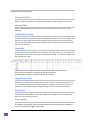
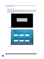
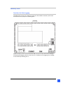
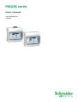
Automatic Load Bank Controller 2 Table of Contents Automatic Load Bank Controller Description .................................................................................................... 5 Operational Features ..................................................................................... 6 Automatic Mode............................................................................................... 6 Manual Mode ................................................................................................... 6 Load Bank Exercising ........................................................................................ 6 Step Delay ......................................................................................................... 6 Temperature Alarm .......................................................................................... 6 Flow Alarm........................................................................................................ 6 Data Logging ..................................................................................................... 6 Wiring ........................................................................................................... 7 Inputs / Outputs ............................................................................................... 7 Load Bank Setup ............................................................................................ 8 Initial Power Up ................................................................................................ 7 Memory Stick Logging ...................................................................................... 8 Logging In.......................................................................................................... 9 Loadbank Setup – Page 1 ................................................................................. 11 Loadbank setup – Page 2 ................................................................................................................... Error ! Bookmark not defined.2 Loadbank Setup – Page 3 ................................................................................. 13 Loadbank Setup – Page 4 ................................................................................................................... Error ! Bookmark not defined.4 Loadbank Exercising ......................................................................................... 115 Load Bank Operation ........................................................................................ 126 Automatic Mode............................................................................................... 126 Manual Mode ................................................................................................... 126 Monitoring ........................................................................................................ 137 Measured Currents........................................................................................... 148 Measured Voltages........................................................................................... 148 Miscellaneous Measurements ......................................................................... 159 Trends Page ...................................................................................................... 159 Fault Page ......................................................................................................... 20 PM3250 Power Meter .................................................................................... 21 Setup................................................................................................................. 21 3 Data Logging with Vijeo Data Manager .......................................................... 25 Software Setup ................................................................................................ 25 Automatic Load Bank Controller Description The TEE Automatic Load Bank Controller (Controller) is a fully featured and programmable load bank controller that monitors and controls the electrical load of any generator in conjunction with Resistive Load Banks to ensure the minimum load requirements of the generator are maintained as set by the manufacture to prevent possible mechanical damage and load testing of generator sets. Through accurate measurement of the generator load the Controller algorithms will call for load steps to be switched in or out from a Load Bank. The Controller also set to run in a load bank exercising mode for maintenance or testing purposes. A menu driven operator panel (HMI) allows easy access to set parameters and utilise the features of the Controller as required for the generator used, its minimum load setting, the load bank and step sizes. For Example: A 1000kW Generator requires a minimum load of 30% (300kW) If the measured load in the generator is only 200kW, the Controller will automatically add an additional 100kW from the load bank by switching in the required combination of resistors. If the load increases say to 250kW, then the Controller will shed 50kW. Once the building load goes above the minimum load of the generator (300kW in this example), no additional load is required from the load bank In this example the following resistors are used, where the Load Bank is engineered to enable load to be added in 0.5kW steps. kW Values 336 168 84 42 21 10.5 3.5 2.5 2 1.5 1 0.5 A contactor will be used to bring in each resistor value. The following are examples of different loads and the contactors being used:- Contactor No. Resistor kW Values 5 20 50 150 200 300 12 336 11 168 x x 10 84 9 42 x x x x x 8 21 x x 7 10.5 6 3.5 x x x 5 2.5 x x x x 4 2 3 1.5 x x x 2 1 1 0.5 x x x x x 55 Operational Features Automatic Mode When in Automatic Mode the Load Bank will respond to load changes automatically. Manual Mode When in Manual Mode the operator can enter the required load or step up / down manually. Load Bank Exercising This feature allows an operator to put the Load Bank Controller into Exercise Mode. The operator can then select what maximum load to put onto the generator, how long to run the exercising, what step increases the generator will make and how long the load will stay on each step. Step Delay A step is classed as the Load Bank switching from one value to the next, up or down. For example if the Load needs to increase from 100kW to 102kW. It can be seen below that there will be four steps. A Step Delay can be adjusted to allow a time delay between each increment. A Step Delay is available for Stepping Up and Stepping Down. The Step delay is the time between each step (in seconds). Temperature Alarm A Temperature probe can be added to the system to allow a Temperature Alarm to be set. A Temperature switch can also be added. This monitors the resistors and can be used to trip the Load Bank if the Temperature goes over the desired temperature. Flow Alarm A Flow Switch can be added to the system which can be used to trip the Load Bank if there is no flow over the resistors. Data Logging The Measured Kilowatts from the Power Meter and the Load that is stepped in via the controller are logged and stored. 6 Wiring Inputs / Outputs Inputs Digital Inputs Input 7 Input 8 Input 9 Input 10 Input 12 Input 13 Analogue Input 1 Input 2 Description High Temperature Switch (N/C = Healthy) Automatic Mode (N/C = Auto) Manual Mode (N/C = Manual) Load Dump (Must be N/C for 3 seconds to activate) Fault Reset No Flow Switch (N/C = Healthy) Analogue Module TM2ALM3LT Temperature 1 (Thermocouple (Type K)) Temperature 2 (Thermocouple (Type K)) Outputs Digital Outputs Output 4 Output 5 Output 6 Start Fan Fault Fan Cool down (Flashes when in Cool Down Mode) Relay Outputs Out 1 Out 2 Out 3 Out 4 Out 5 Out 6 Out 7 Out 8 Out 9 Out 10 Out 11 Out 12 Relay Module TM2DRA16RT Contactor 1 Contactor 2 Contactor 3 Contactor 4 Contactor 5 Contactor 6 Contactor 7 Contactor 8 Contactor 9 Contactor 10 Contactor 11 Contactor 12 7 Load Bank Setup Initial Power Up On initial power up, the following screen will prompt for the date. The date is required to be set if data logging is required during the operation, such as generating a report for generator exercising. The current date can be set. Then Press OK 8 Memory Stick Provision for Data Logging The HMI Touch Screen has a USB port on the rear that enables a memory stick to be connected for the purpose of collecting data When a memory stick is inserted into the USB 1 port, the screen will show a message confirming the logging volume or that there is no medium or for logging. This message can be closed by touching the X. 9 Fan Setup Fan Run On Time - Enter a time here that the Fan will continue to operate after the Load Bank is switched out of Auto, Manual or Exercise Mode. Example if you want to run the Fan for 10 minutes, enter 10. Fan Remaining Time - After the Load Bank has been switched out of Auto, Manual or Exercise Mode, a countdown of remaining time will be displayed here and on the Main Display. The FAN OFF button is used to manually start and stop the Fan. WARNING The fan run on time is critical to the resistor temperature limits and values should only be entered based on the resistor manufacturer’s recommendations. Loss of power to the fan during operation due to power failure, fuel capacity or by manual operator command will void manufacturer’s warranty. 10 Loadbank Exercising From the Main Monitor Screen, select ‘Menu’ then ‘Exercise. This screen shall only be configured if Load Bank Exercising is being used. Test Load – This is the maximum load the Load Bank will bring on. Cycle Time – This is the time that the Load Bank exercising will run for. Remaining Time – The time remaining for the exercise mode. No. Of Steps – This will be the number of steps that the load bank will bring in between zero load and Max Load. Example: - If 300kW is selected as the Test Load and No. Of Steps is 10. Then the Loadbank will pause for ‘Step Time’ every 30kW. (300kW / 10 = 30) Step Time – This is the time the Load Bank will pause on each step going up and down. Engaged – This shows how much load is currently online (stepped in). The ‘Auto Exercise’ button will start or stop the Exercise Mode. The Trend button will take the user to the Trends page where engaged load and measured load are being trended and stored. NOTE: Auto Exercise only works when not in Auto or Man. 11 Load Bank Operation To operate the Load Bank Controller in Automatic Mode or Manual Mode the following steps shall be followed. Automatic Mode Select ‘Auto Man’. The following screen is displayed. Select ‘Auto Off’ to run in Auto Mode. Auto Off will change to Auto On when in Automatic Mode. The Load Bank Controller will now adjust the Load on the Generator Automatically by ‘stepping in’ the applicable resistors from the Load Bank. Manual Mode Select ‘Man Off’ to run in Manual Mode. Man Off will change to Man On when in Manual Mode. 12 The operator can now enter a value straight into the screen to adjust the Load Bank Load Manually or the operator can step up or down in increments of the smallest resistor in the setup screens. Monitoring From the controllers Main Screen the following information can be seen. The operator can monitor the Measured Load From the Main Screen. The operator can monitor the Engaged Load the total load ‘stepped in’ by the Load Bank. of the supplied installation. from the Load Bank. This is The Status of the Load Bank is displayed. The following statuses are displayed depending on the status of the Load Bank. 1. 2. 3. 4. 5. 6. 7. 8. OFF – Load Bank is Off Manual Mode – The Load Bank is operating in Manual Mode Exercise Mode – The Load Bank is operating in Exercise Mode. Auto Mode – The Load Bank is operating in Automatic Mode. Load Dump – The Load Bank has been placed in Load Dump Mode. Temp Trip – The temperature Sensor or Switch has tripped the Load Bank. Flow Alarm – The Flow Switch has operated and tripped the Load Bank. Temp Alarm – The temperature sensor has reached the warning level. The user can also see that the Cooling Fan is either running or Not Running via the indicator on the Status. Fan NOT Running Fan Running Fan Remaining Running Remaining Time NOTE 1: There is also an output configured that can be used to Flash an external lamp to indicate that the Fan is still Running. NOTE: If Power is Switched off to the Load Bank Controller the Fan may be switched off too soon without allowing the resistors to cool down correctly. This is not advisable. 13 The following pages show various readings from the installed Power Meter. Measured Currents From the Menu Screen Page select ‘Monitor’. Measured Voltages Select ‘Next’. 14 Miscellaneous Measurements Trends Page The Trend Page indicates the Measured Load and the Engaged Load. 15 Fault Page Full access to this page is only accessible when logged in. From the below page select ‘Faults’. The Faults page is shown. From this page the Total Run Time of the Load Bank Controller can be seen. The Run Hours of the Fan is also recorded. The ‘Fan Power Fail Count’ is used to record if the Power has been switched off while the Fan is still running. The Fault Log records the instances the High Temperature or Low Flow Alarm has occurred. A High Temperature Alarm is indicated by a 1. A Flow Alarm is indicated by a 2. The ‘Hi Temp’ indicates how many High Temperature Faults have occurred. The ‘No Flo’ indicates how many low Flow Faults have occurred. Both the Hi Temp and the No Flo totals can be reset by touching the total number to bring up a numerical pop up. 16 PM3250 Power Meter The Power Meter must be setup to correctly read the Supplied Power to the utility being fed from the Generator. The Power Meter is used to measure the Voltage and the Current. It then calculates various readings for use in the Load Bank Controller. Therefore it is critical that the Power Meter is setup correctly. The Power Meter must be installed correctly and this may vary depending on the application. If in doubt, contact Thermal Electric Elements. Please consult with PM3200 series – Power Meters User Manual when setting up Power Meter. Of the more common setups, the 3 Phase Voltages and 3 Phase Currents are connected back to the Power Meter. See diagram below. Setup The power meter features a sophisticated and intuitive human machine interface (HMI) with signaling. LEDs, a graphic display, and contextual menu buttons for accessing the information required to operate the power meter and modify parameter settings. The Navigation menu allows the user to display, configure, and reset parameters. 17 General Display 18 19 Important parameters to setup are:Wire – Type of wiring connection e.g. 3.3Ct Ratio – The ratio of the Current Transformers (Cts) being used. For further information on the PM3250, please see document PM3200 series – Power Meters User Manual. Communications setup for PM3250 to PLC PM3250 Address – 2 Baudrate – 19200 Parity – EVEN 20 Using Vijeo Designer Data Manager The following procedure allows for the data logged from the load bank controller to be viewed in an Excel format for the purpose of reporting based on time stamping. The Vijeo Designer Data Manager program must be loaded on to a suitable PC prior to beginning the data transfer. The data file being used is a .DAT file that will be located in the USB memory stick located in the HMI of the load bank controller. Open the Vijeo Designer Data Manager program, select Local Files as the media and click “next”. Select Convert Recipe or Data Logging Files and click “next”. 21 Select the DATA folder of the memory stick files from the load bank controller as the Input Folder. Create a destination folder for your converted files. E.g. C:\Data Log 22 From the Options tab, select the file options as above. Click OK. Select Convert and you should see a successful data conversion to a text file which will be located in your Output Folder created earlier. 23 Launch Microsoft Excel and locate your data file from the Text option tab in the Data section. Click Open once you have located the file. 24 Follow the Text Import Wizard Select Comma in the Delimiters 25 Select Finish Click OK to import the data to the page. 26 Highlight Column A and select “More Number Formats” from the drop down menu for the cell format. Select Custom if you wish to retain Date and Time including minutes and seconds. In the example here, we needed to add “:s” to get the seconds to display. 27 This view shows the date and time including hours, minutes and seconds. In the example above, the data in column A was changed to “time” so as to get the best increments for the data chart. There are many options available in Excel to produce data in useable formats 28 29 30