1
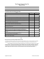
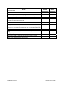
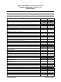
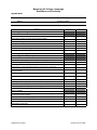
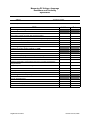
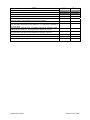
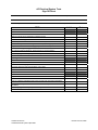
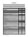
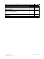
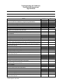
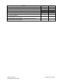
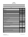
SIGN-OFF SHEET INSTRUCTIONS
Attached are copies of the 14 sign-off sheets, required of all technicians
who plan to test for certification.
Here is what to do:
1. Make Copies of all 14 sheets for each technician.
2. Place copies in Training Folder
3. Brief Technicians on what the sign-off sheets are for and how they
are to be used.
4. Select a responsible person to actually witness the hands-on
demonstration of the procedures noted.
5. Have responsible person sign off on the completed task and date.
6. File completed sign-off sheets in Technician Training folder
7. Keep on file at the dealership.
NOTE: If technician leaves employ at dealership allow technician to
take the folder with him/her.
Time Propane Pressure Drop Test
Sign-Off Sheet
Printed Technician Name
Social Security Number
Address
Telephone Number
City
State
Time Pressure Drop Test Conducted at the Range
STEP
Zip Code
Initials
Date
Did the Candidate:
Prepare document (work order, PDI form, etc.) to record time pressure drop test
results?
Ensure the temperature of both air and piping was approximately the same?
Ensure a uniform temperature was maintained throughout the test procedure?
Ensure the propane system is turned off at the service valve?
Turn off the burner valves on the range and gas valves on other appliances?
Turn off all open pilot lights?
Turn propane system on at the service valve?
Listen to the regulator for sounds of escaping propane that would indicate an
open line? Silence indicates the regulator has locked up.
Remove a range burner and attach a manometer to the range burner spud?
Turn on the burner valve with the manometer and ensure the propane system is
pressurized to 10-14” W.C?
Turn off propane system at the service valve?
Slowly open a second range burner and reduce the operating pressure to a
nominal 8” W.C. Turn range burner off after achieving a nominal 8” W.C.?
Monitor the manometer for a minimum of 3 minutes? Locate and repair any
leak(s) and retest until a successful test is accomplished? (Go to Leak Test Signoff Sheet)
Turn off the range burner with the manometer, disconnect the manometer from
the range burner spud, and reconnect the range burner?
Return propane system to proper operation?
Document test results on appropriate documentation. Indicate pressure, time,
duration of test, date, and sign?
OR
Time Pressure Drop Test Using a Propane System Test Kit
The following procedures should be used to connect the Propane System Test Kit. These procedures are provided
as guidance but are not included in the procedures to be followed in conducting the Time Pressure Drop Test.
With all appliances turned off and the propane supply turned off, disconnect the low-pressure hose or piping
from the regulator. Connect the 3/8” female flare of the Test Kit flex hose to the regulator outlet fitting. Attach the
low-pressure hose, previously attached to the regulator, to the half-union end of the Test Kit. Attach the manometer
hose to the 5/16” hose barb on the Test Kit. Make sure the gas cock on the Test Kit is closed. Slowly turn the
propane supply back on at the service valve. Conduct a leak test to ensure all connections are leak free.
Registered Technician
Revised June 23, 2008
STEP
Initials
Date
Did the Candidate:
Prepare documentation (work order, PDI form, etc) to record the Time Pressure
Drop Test results?
Ensure the temperature of both air and piping was approximately the same?
Ensure a uniform temperature was maintained throughout the test procedure?
Ensure the propane system is turned off at the service valve?
Ensure all appliances are turned off?
Ensure all open pilot lights are turned off?
Turn propane system on slowly at the service valve to bring pressure to between
7.5 and 8.5 “W.C.”?
Turn propane off at the service valve?
Monitor the manometer for a period of three minutes? Locate and repair leak(s)
and retest until a successful test (no pressure drop) is accomplished? (See Leak
Test sign-off sheet)
Bleed the propane pressure from the system using the gas cock on the Test Kit?
Remove the Test Kit from the system and reattach the low-pressure hose or
piping?
Turn propane system on at the service valve?
Leak test the low-pressure hose or piping connection?
Document test results on appropriate documentation indicating observed
pressure, time, duration of the test, date and sign?
Registered Technician
Revised June 23, 2008
System Operating Pressure Test, Leak Test,
Regulator Adjustment & Lock Up Tests
Sign-Off Sheet
Printed Technician Name
Social Security Number
Address
Telephone Number
City
State
STEP
Zip Code
Initials
Date
System Operating Pressure Test
The following procedures apply using test apparatus shown in
figure 3-10, page 3-10 of the RVIA Propane Systems Textbook.
Did the candidate
Prepare document (work order, PDI form, etc.) to record test results?
Ensure the propane system is turned off at the container service valve?
Turn off all appliances?
Disconnect the propane low pressure hose from the regulator (use backup
wrench)?
Connect test apparatus to the regulator?
Connect the Propane low pressure hose to the test apparatus?
Install manometer to the apparatus?
Open service valve on the container?
Open gas cock on test apparatus (simulates 50 % flow)?
Measure inches of water column WC on manometer 10.5-11.5 WC?
Adjust regulator if measured WC is incorrect?
Document test results?
Propane Regulator Adjustment
If Propane pressure is greater than 11.5" WC
Did the candidate
Prepare documentation?
Remove dust cap?
Adjust by turning the adjustment screw counter clockwise until proper pressure is
achieved?
Reinstall dust cap?
Document results?
If Propane pressure is less than 10.5" WC
Did the candidate
Remove dust cap?
Adjust by turning the adjustment screw clockwise until proper pressure is
achieved?
Reinstall dust cap?
Document results?
Propane Regulator Lockup Test
Upon completion of the Operating Pressure Test and Regulator Adjustment
Did the candidate
Close the cock on apparatus?
Monitor propane pressure on manometer for 3 minutes?
If pressure exceeds 14" WC replace regulator?
Turn off Propane at the service valve at the container?
Remove test apparatus?
Registered Technician
Revised June 23, 2008
STEP
Initials
Date
Reconnect low pressure hose to regulator (use backup wrench)?
Conduct a leak test on any fittings that were disconnected?
Return system back to proper operation?
Document results?
Propane Leak Test
This test must be preformed any time a propane line is opened or a
leak is indicated during a timed pressure test
Perform either of the following methods.
Using an electronic leak detector
Did the candidate
Prepare documentation?
Open service valve to pressurize propane system?
Turn off all appliances?
Turn on the electronic leak detector?
Test the electronic leak detector using a butane lighter?
Operate the electronic leak detector per the manufactures recommendation?
Repair or tighten connections using backup wrenches?
Document results?
Using a non corrosive leak detector solution
Did the candidate
Open service valve to pressurize propane system?
Turn off all appliances?
Cover each connection with the solution?
Monitor for bubbles if leak is present?
Repair or tighten connections using backup wrenches?
Document results?
Registered Technician
Revised June 23, 2008
Measuring AC Voltage, Amperage
Resistance and Continuity
Sign-Off Sheet
Printed Technician Name
Social Security Number
Address
Telephone Number
City
State
STEP
Zip Code
Initials
Date
Measuring AC Voltage
Did the candidate
Set VOM to highest AC voltage scale?
Ensure meter capacity is greater than expected voltage?
Measure AC voltage at various locations (i.e. AC Receptacles)?
Connect black lead to circuit neutral?
Connect red lead to the live side of the circuit?
Switch VOM down to best range?
Read the indicated value?
Measuring Amperage (Current)
When using an in-line (series) ammeter or VOM
Did the candidate
Ensure meter capacity is greater than expected amperage?
Set VOM to highest AC amps scale?
Turn off power to the circuit?
Disconnect the circuit at the point where the current is to be measured?
Install the VOM leads in series between the source of current and the device
being measured?
Turn on the power to the device being measured?
Switch the VOM scale to the lowest safe range?
Read the indicated current?
Turn off power to the circuit?
Return the circuit to its original condition
Accurately diagnose and repair problems if any exist?
When using a clamp-on meter
Did the candidate
Clamp the jaws of the meter around one of the conductors feeding power to a
live electrical circuit or device?
Read the current draw in amperage?
Isolate the component from the circuit
Set the ammeter to the proper amp scale
Read results on the meter
Registered Technician
Revised June 23, 2008
STEP
Initials
Date
Checking Continuity
Did the candidate
Turn off all VAC power?
Isolate the component to be checked by disconnecting all the wires?
Set the VOM to the Ohms scale?
Place one probe on each terminal of the item to be checked?
Shorted Circuit (i.e., Two wires touching, or a closed switch). Meter reading will
show Zero Ohms (sometimes a meter will read .1 to .3 ohms due to resistance in
the meter leads).
Open Circuit (i.e., Wire cut in half, or a switch that won’t make continuity). Meter
reading will show infinity (i.e., most digital meters will read OL or OFL).
Grounded Circuit (i.e., Bare wire touching ground). Meter will read the same way
as a short (zero) when the circuit is tested from a conductor to ground>
Read the indicated value?
Accurately diagnose and repair problems if any exist?
Compare the reading to component specifications
Registered Technician
Revised June 23, 2008
Measuring DC Voltage, Amperage
Resistance and Continuity
Sign-Off Sheet
Printed Technician Name
Social Security Number
Address
Telephone Number
City
State
STEP
Zip Code
Initials
Date
Measuring DC Voltage
Did the candidate
Set VOM to DC voltage scale?
Ensure meter capacity is greater than expected voltage?
Measure DC voltage at various locations (i.e. brake lights, tail lights)?
Connect black lead to circuit ground?
Connect red lead to the live side of the circuit?
Read the indicated value?
Measuring Amperage (Current)
If using an in-line (series) ammeter or VOM
Did the candidate
Set VOM to DC amps scale?
Ensure meter capacity is greater than expected amperage?
Turn off power to the circuit?
Disconnect the circuit at the point where the current is to be measured?
Install the VOM leads in series between the source of current and the device
being measured?
Turn on the power to the device being measured?
Read the indicated value?
Turn off power to the circuit?
Return the circuit to its original condition?
Measuring Resistance (Ohms)
Did the candidate
Turn off electrical power?
Isolate the component from the circuit?
Set the VOM to the proper Ohms scale?
Read results on the meter?
Registered Technician
Revised June 23, 2008
STEP
Initials
Date
Checking Continuity
Did the candidate
Turn off all VDC power?
Isolate the component to be checked by disconnecting all the wires?
Set the VOM to the Ohms scale?
Place one probe on each terminal of the item to be checked?
Shorted Circuit (i.e., Two wires touching, or a closed switch). Meter reading will
show Zero Ohms (sometimes a meter will read .1 to .3 ohms due to resistance in
the meter leads)
Open Circuit (i.e., Wire cut in half, or a switch that wont make continuity). Meter
reading will show infinity (i.e., most digital meters will read OL or OFL)
Grounded Circuit (i.e., Bare wire touching ground). Meter will read the same way
as a short (zero) when the circuit is tested from a conductor to ground
Read the indicated value?
Accurately diagnose and repair problems if any exist?
Compare the reading to component specifications?
Registered Technician
Revised June 23, 2008
AC Electrical System Tests
Sign-Off Sheet
Printed Technician Name
Social Security Number
Address
Telephone Number
City
State
STEP
Zip Code
Initials
Date
Hot Skin Test
Did the candidate
Prepare Documentation?
Make sure shore line is plugged into 120VAC source?
Set VOM to AC voltage scale?
Place one probe on a bare metal surface of the RV (i.e., Door frame, Chassis)?
Place the other probe to an earth ground source (i.e., water pipe)?
Repeat the test at least twice changing the placement of the probe?
If there is no voltage reading present the skin is not hot?
Any voltage reading indicates an electrical short or reverse polarity?
Accurately diagnose and repair problems if any exist?
Document Results?
Polarity Test
Did the candidate
Prepare Documentation?
Perform the test using a ground monitor or circuit tester?
Accurately diagnose and repair problems if any exist?
Document Results?
GFCI Test
Did the candidate
Prepare Documentation?
Push the test button on the GFI outlet or breaker?
Test any 120VAC receptacles within 5 feet of water and all outside receptacles?
Use a GFCI Polarity Tester to check outlets that are GFCI protected but have no
test button.
Accurately diagnose and repair problems if any exist?
Document Results?
Certified Technician
Certified Electrical Systems Specialist
Revised June 23, 2008
Air Conditioning
Sign-Off Sheet
Printed Technician Name
Social Security Number
Address
Telephone Number
City
State
STEP
Zip Code
Initials
Date
Install Or Verify The Accuracy Of An Air Conditioner’s Installation
The candidate must describe and record these characteristics of
an air conditioner.
Did the candidate
Record the air conditioner model number?
Record the air conditioner serial number?
Record the type of air conditioner (ducted or non-ducted)?
Indicate OEM or Aftermarket installation?
Verify compatibility of the component parts (i.e., Rooftop unit, Ceiling plenum,
Wall control)?
The candidate must confirm the proper installation of an air
conditioner (including the ceiling plenum)
Did the candidate
Verify the air conditioner is bolted down properly (Gasket compression
approximately 50%)?
Verify proper ceiling plenum installation including return and supply air
separation?
Verify installation wiring conforms to all applicable codes, proper wire gauge,
breaker size, etc.?
Verify adequacy of ducting, vents, and size of registers per installation
instructions/service manual?
Accurately diagnose and repair problems, if any exist, in accordance with the
installation instructions?
Evaluate Air Conditioner Performance
Measure line voltage to the air conditioner
Did the candidate
Use a VOM to check incoming static voltage at the air conditioner voltage
connection points?
Start the air conditioner on high cool and check this voltage reading again after
applying the load?
Interpret the accuracy and validity of these voltage readings (should be between
103.5 & 126.5 VAC)?
Correctly diagnose and repair problems, if any exist, in accordance with the
service manual if voltage readings are not within the pre-described limits?
Measure the temperature difference across the evaporator (supply
& return air temperatures)
Did the candidate
Start the air conditioner in the high cool position?
Allow the air conditioner to run for a minimum of 30 minutes?
Open all discharge and supply air registers completely?
Place a thermometer near the return air grille/louvers and measure the air
temperature?
Place a thermometer in the supply register/louver and measure the air
temperature?
Verify accuracy and validity of this calculation to the manufacturer specifications;
20 degrees difference nominal (See service manual)?
Accurately diagnose and repair problems, if any exist, in accordance with the
service manual?
Certified Technician
Certified Appliance Specialist
Revised June 23, 2008
STEP
Initials
Date
Measure the compressor amperage
Did the candidate
Start the air conditioner in the high cool position?
Allow the air conditioner to run for a minimum of 30 minutes?
Measure the outdoor ambient temperature?
Record the compressor rated load amperage (RLA) printed on the air
conditioners rating plate?
Use the information found in the service manual to calculate correct amperage
based on RLA and outdoor temperature?
Read the compressor amperage with an Ammeter?
Confirm the measure compressor amperage and calculated amperages are
approx. equal?
Accurately diagnose and repair problems, if any exist, in accordance with the
service manual?
Subtract the supply air temperature from the return air temperature?
Certified Technician
Certified Appliance Specialist
Revised June 23, 2008
Troubleshooting Air Conditioner
Key Electrical Components
Sign-Off Sheet
Printed Technician Name
Social Security Number
Address
Telephone Number
City
State
STEP
Zip Code
Initials
Date
Note: Due to product differences the candidate must consult the
service manual for individual component specifications,
procedures, and sequence of operation
Air Conditioner Compressor
Did the candidate
Correctly measure compressor amperage?
Correctly measure resistance of the compressor motor windings?
Remove all electrical power from the air conditioner; remove all wires from the
compressor; check terminals C&R, C&S, R&S?
Measure running voltage at the proper location on the compressor?
Accurately diagnose compressor problems, if any exist, in accordance with the
service manual?
Air Conditioner Fan Motor
Did the candidate
Correctly measure fan motor amperage?
Correctly measure resistance of the fan motor windings?
Remove all electrical power from the air conditioner; remove all wires from the
fan motor; check motor windings for short, open or ground (see service manual)?
Measure running voltage at the proper location on the fan motor?
Accurately diagnose and repair fan motor problems, if any exist, in accordance
with the service manual?
Air Conditioner Capacitor(s)
Did the candidate
Properly discharge the capacitor(s) per the service manual?
Properly test the capacitor(s) per the service manual?
Accurately diagnose and repair capacitor problems, if any exist, in accordance
with the service manual?
Select either manual thermostat or wall thermostat
Manual Thermostat
Did the candidate
Remove all electrical power from the air conditioner; remove all wires from the
thermostat; check the thermostat with an Ohmmeter?
Accurately diagnose and repair the thermostat problems, if any exist, in
accordance with the service manual?
Manual Selector Switch
Did the candidate
Remove electrical power from the air conditioner; remove wires from the switch;
check the selector switch with an Ohmmeter?
Wall Thermostat
Did the candidate
Measure low voltage power into the wall thermostat?
Measure low voltage power out of the wall thermostat?
Accurately diagnose and repair thermostat problems, if any exist, in accordance
with the service manual?
Certified Technician
Certified Appliance Specialist
Revised June 23, 2008
STEP
Initials
Date
Upper Control Box Assembly
Did the candidate
Measure low voltage power from the wall thermostat to the control box?
Measure high voltage power (120VAC) out of the upper control box assembly to
the rooftop air conditioner?
Accurately diagnose and repair control box assembly problems, if any exist, in
accordance with the service manual?
Accurately diagnose and repair selector switch problems, if any exist, in
accordance with the service manual?
Certified Technician
Certified Appliance Specialist
Revised June 23, 2008
Batteries, Inverters and Converters
Sign-Off Sheet
Printed Technician Name
Social Security Number
Address
Telephone Number
City
State
STEP
Zip Code
Initials
Date
Draw a Diagram of Batteries in a Parallel Circuit
Draw a Diagram of Batteries in a Series Circuit
Perform a Battery Load Test
Did the candidate
Wear appropriate protective clothing?
Disconnect batteries from coach?
Hookup battery load tester according manufacturer specifications?
Perform Battery Maintenance
Did the candidate
Wear appropriate protective clothing?
Clean terminals?
Clean cable clamps?
Clean battery tops?
Check and add battery fluid level on non-maintenance free batteries?
Check Inverter
Did the candidate
Remove shore power and shut off generator?
Check battery? It should be fully charged. If it is not, charge battery
Turn the inverter on?
Measure DC voltage input at the inverter? Nominal voltage should be 12 VDC
Measure AC voltage output at the inverter? Nominal voltage should be 120 VAC
Accurately diagnose and repair problems if any exist?
Check Converter
Did the candidate
Measure AC voltage into the converter? Nominal voltage should be 90-135 VAC
or 120 VAC with a RMS meter.
Measure DC voltage output? Loaded and unloaded. Nominal voltage should be
within manufacturer’s specifications.
Test the converter’s battery charger at the converter?
Turn off all 12 volt loads?
Disconnect battery cable at the converter?
Set the VOM on VDC scale?
Connect positive probe to the converter charge lug?
Connect the negative probe to converter ground lug?
Measure voltage. If voltage is less than 13 VDC or more than 14.2 VDC a
problem may exist?
Accurately diagnose and repair problems if any exist?
Certified Technician
Certified Electrical Systems Specialist
Revised June 23, 2008
Furnace
Sign-Off Sheet
Printed Technician Name
Social Security Number
Address
Telephone Number
City
State
Zip Code
STEP
Initials
Date
Install or Verify the Accuracy of a Furnace’s Installation
The candidate must describe and record these characteristics of a
furnace.
Did the candidate
Record the furnace model number?
Record the furnace serial number?
Record the type of furnace system?
Indicate OEM or Aftermarket installation?
The candidate must confirm the proper installation of a furnace.
Did the candidate
Verify proper ducting?
Verify proper return air?
Verify proper gas pressure at furnace?
Verify proper propane connections and conduct a leak test ?
Document leak test results?
Verify proper DC/AC voltage at furnace?
Verify proper exhaust vent system?
Verify proper seals at door, vents etc.?
Accurately diagnose and repair installation problems, if any exist, in accordance with
the installation manual?
Evaluate Furnace Performance
Measure line voltage at the furnace
Did the candidate
Check incoming voltage at the wire connections on side of furnace? Nominal voltage
should be 10.5-13.5 VDC under unloaded condition.
Turn furnace on?
Verify ignition?
Check voltage at the wire connections on side of furnace? Nominal voltage should be
10.5-13.5 VDC under loaded condition.
Accurately diagnose and repair problems, if any exist, in accordance with the service
manual?
Measure propane pressure at furnace
Did the candidate
Turn propane off at container?
Install manometer at pressure test port?
Turn propane on at container?
Check for proper gas pressure (see service manual)?
Document measurement results?
Accurately diagnose and repair problems, if any exist, in accordance with the service
manual?
Certified Technician
Certified Appliance Specialist
Revised June 23, 2008
STEP
Initials
Date
Evaluate proper air flow
Did the candidate
Open all discharge registers and any closeable registers(see installation and or
service manual for requirements)?
Verify air discharge by feel or using an air speed indicator?
Verify that the discharge is warm?
Accurately diagnose and repair problems, if any exist, in accordance with the service
manual?
Evaluate return air flow
Did the candidate
Verify proper return air opening size (see installation and or installation manual)?
Accurately diagnose and repair problems, if any exist, in accordance with the service
manual?
Certified Technician
Certified Appliance Specialist
Revised June 23, 2008
Troubleshooting Key Furnace
Electrical Components
Sign-Off Sheet
Printed Technician Name
Social Security Number
Address
Telephone Number
City
State
STEP
Zip Code
Initials
Date
Troubleshoot Key Furnace Electrical Components
Did the candidate verify sequence of operation per the service manual to
evaluate the following components?
Thermostat
Did the candidate
Verify proper height and location per installation and or service manual?
Verify voltage to thermostat and voltage out of thermostat to furnace (see service
manual)?
On/Off Switch
Did the candidate
Remove power wires and check switch for continuity using an ohmmeter?
Accurately diagnose and repair problems, if any exist, in accordance with the
service manual?
Circuit Breaker (If applicable)
Did the candidate
Measure DC voltage in and out of circuit breaker?
Accurately diagnose and repair problems, if any exist, in accordance with the
service manual?
Time Delay Relay (if applicable)
Did the candidate
Confirm DC voltage at proper terminals (refer to service manual)?
Accurately diagnose and repair problems, if any exist, in accordance with the
service manual?
Blower Motor
Did the candidate
Confirm DC voltage to blower motor?
Measure DC amperage at motor (see service manual)?
Accurately diagnose and repair problems, if any exist, in accordance with the
service manual?
Limit Switch
Did the candidate
Verify continuity or DC voltage through limit switch?
Accurately diagnose and repair problems, if any exist, in accordance with the
service manual?
Sail Switch
Did the candidate
Verify continuity or DC voltage through sail switch?
Accurately diagnose and repair problems, if any exist, in accordance with the
service manual?
Certified Technician
Certified Appliance Specialist
Revised June 23, 2008
STEP
Initials
Date
Either Fan Control Circuit Board
Verify proper DC voltage to circuit board (see manual)?
Verify function of circuit board (see manual functions)?
Spark
DC voltage to gas valve
Sense flame
Energize relay to start fan
Accurately diagnose and repair problems, if any exist, in accordance with the
service manual?
Or Ignition Board
Did the candidate
Verify proper DC voltage to ignition board (see manual)?
Verify function of ignition board (see manual functions)?
Spark
DC voltage to gas valve
Sense flame
Accurately diagnose and repair problems, if any exist, in accordance with the
service manual?
Gas Valve
Did the candidate
Measure proper voltage at valve?
Remove power wires and check coils for proper resistance 30-50 ohms?
Check for proper gas flow exiting valve orphic (if ignition fails check by smell or
use manometer)?
Accurately diagnose and repair problems, if any exist, in accordance with the
service manual?
Electrode
Did the candidate
Check for proper gap (see manual)?
Check for proper spark across electrode to ground?
Accurately diagnose and repair problems, if any exist, in accordance with the
service manual?
Did the candidate
Certified Technician
Certified Appliance Specialist
Revised June 23, 2008
Generator
Sign-Off Sheet
Printed Technician Name
Social Security Number
Address
Telephone Number
City
State
STEP
Zip Code
Initials
Date
Install or Verify the Accuracy of a Generator’s Installation
The candidate must describe and record these characteristics of a
generator set
Did the candidate
Record the generator’s make?
Record the generator’s model number?
Record the generator’s Serial number?
Determine the generator’s kilowatt (kW) rating?
Determine the generator’s maximum amperage output?
Identify the generator’s fuel type?
The candidate must confirm the proper installation of a
generator
Did the candidate
Verify generator mounting is level and will support the weight of the generator
set?
Verify the proper generator top, side, back and front clearances per the
installation manual?
Verify the generator compartment is sealed from the coach interior?
Verify all AC and DC connections and routings comply with NEC codes?
Verify fuel line and routings and fuel tank pickup comply with all applicable
codes?
Verify cooling air inlet and cooling air discharge is sized correctly per installation
manual?
Verify the engine exhaust pipes are properly installed per installation manual and
comply with all applicable codes?
Accurately diagnose and repair any installation problems in accordance with the
installation instructions?
Evaluate Generator Performance
Measure AC output voltage at no-load
Did the Candidate
Use a voltmeter set on the AC scale to check output voltage at the junction box?
Verify the voltage reading is correct per the service manual?
Accurately diagnose and repair problems, if any exist, in accordance with the
service manual?
Measure AC output voltage at full rated load
Did the Candidate
Use a voltmeter set on the AC scale to check output voltage at the junction box?
Use loadbank to properly apply maximum rated load on generator set per service
manual? Indicate if loadbank is available.
Verify the voltage reading is correct per the service manual?
Accurately diagnose and repair problems, if any exist, in accordance with the
service manual?
Measure proper AC voltage frequency (engine RPM) at no-load
Did the Candidate
Certified Technician
Certified Electrical Systems Specialist
Revised June 23, 2008
STEP
Initials
Date
Use a frequency meter to check output voltage frequency at the junction box?
Verify the frequency reading is correct per the service manual?
Accurately diagnose and repair problems, if any exist, in accordance with the
service manual?
Measure proper AC voltage frequency (engine RPM) at full load
Did the Candidate
Use a frequency meter to check output voltage frequency at the junction box?
Use loadbank to properly apply max rated load on generator set per service
manual? Indicate if loadbank is available.
Verify the frequency reading is correct per the service manual?
Accurately diagnose and repair problems, if any exist, in accordance with the
service manual?
Troubleshoot Key Generator Components by Sequence of
Operation
Start Solenoid
Did the candidate measure DC voltage at the proper terminal per the service
manual?
Starter Motor
Did the candidate measure DC voltage at the proper terminals per the service
manual?
Ignition System
Did the candidate
Use a spark tester to check if ignition is present?
Visually inspect spark plug and reset plug to proper gap?
Use ohmmeter to measure resistance of the primary and secondary winding of
the ignition coil?
Fuel System
Did the candidate
Verify fuel tank level is greater than 1/4?
Use voltmeter set on the DC scale, measure voltage to the fuel pump per the
service manual?
Measure fuel pressure between the fuel pump and carburetor?
Use voltmeter set on the DC scale, measure voltage to the fuel solenoid per the
service manual?
Generator System
Did the candidate
Measure field flash voltage using a voltmeter set on the DC scale. Measure
voltage per the service manual?
Check resistance of the rotor using an ohmmeter per the service manual?
Accurately diagnose and repair problems, if any exist, in accordance with the
service manual?
Certified Technician
Certified Electrical Systems Specialist
Revised June 23, 2008
Water Heater
Sign-Off Sheet
Printed Technician Name
Social Security Number
Address
Telephone Number
City
State
STEP
Zip Code
Initials
Date
Install or Verify The Accuracy of a Water Heater’s Installation
The candidate must describe and record these characteristics of a
water heater.
Did the candidate
Record the water heater model number?
Record the water heater serial number?
Verify type of control system?
The candidate must confirm the proper installation of a unit
Did the candidate
Check the seal around the flange?
Confirm the vent is clear and properly gapped from door screen (0 to 1/4" - see
installation manual)?
Confirm the gas line is properly sealed from interior of coach?
Verify wiring complies with NEC code (if applicable)?
Conduct a leak test on the propane connection to the water heater?
Verify the water heater is properly supported?
Accurately diagnose and repair problems, if any exist, in accordance with the
installation instructions?
Evaluate Water Heater Performance
Measure propane pressure at water heater
Did the candidate
Turn propane off at the container?
Install manometer on the provided pressure test port?
Turn propane on at the container?
Check for proper propane pressure (see service manual)?
Document results?
Accurately diagnose and repair problems, if any exist, in accordance with the
service manual?
Verify customer complaint
Did the candidate
Visually inspect gas flame, burner tube, flu box, and wires?
Troubleshoot Key Components
Determine the proper pilot control type ( pilot, DSI or electric)
Pilot Control
Gas valve/ECO
Did the candidate remove the thermocouple and measure for continuity?
Pilot assembly
Did the candidate check the pilot for proper flame (see service manual)?
Thermocouple
Did the candidate measure millivolts in heated state (12 millivolts)?
Burner
Did the candidate check for blockage at the orifice?
Certified Technician
Certified Appliance Specialist
Revised June 23, 2008
STEP
Initials
Date
DSI Control
Switch
Did the candidate
Determine proper 12 VDC and ground to switch?
Verify proper wiring (refer to service manual)?
Thermostat
Did the candidate test for voltage to thermostat or ECO?
Circuit Board
Did the candidate check for power to the circuit board from thermostat/ECO?
Gas Valve
Did the candidate
Check for power coming from board/ECO?
Disconnect power source and measure ohms on coils on valve (refer to service
manual)?
Electrode
Did the candidate
Check for proper gap (refer to service manual)?
Check for spark at proper point on electrode?
Visually inspect the electrode wire?
Burner
Did the candidate
Inspect burner for proper flame and adjust as necessary (see service manual)?
Accurately diagnose and repair problems, if any exist, in accordance with the
service manual?
Electric Control
Switch
Did the candidate test for proper voltage to switch?
ECO
Did the candidate test for power from switch?
Thermostat
Did the candidate test for power from ECO?
Heating Element
Did the candidate
Test for power from thermostat?
Did the candidate disconnect power to heating element and perform an ohms
test (see service manual)
Accurately diagnose and repair problems, if any exist, in accordance with the
service manual?
Certified Technician
Certified Appliance Specialist
Revised June 23, 2008
Refrigerator
Sign-Off Sheet
Printed Technician Name
Social Security Number
Address
Telephone Number
City
State
STEP
Zip Code
Initials
Date
Install or Verify the Accuracy of a Refrigerator’s Installation
The candidate must describe and record these characteristics of a
refrigerator
Did the candidate
Record the refrigerator model number?
Record the refrigerator serial number?
Verify the refrigerator’s type of control system?
The candidate must confirm the proper installation of a
refrigerator
Did the candidate
Confirm proper side, top, and rear clearances ?
Confirm proper venting per service or installation manual (i.e., bottom, upper,
side, or roof vent)?
Confirm the refrigerator compartment is properly sealed from interior of coach
(see service or installation manual)?
Verify wiring complies to NEC code?
Verify proper propane connection to refrigerator (leak test)?
Accurately diagnose and repair installation problems, if any exist, in accordance
with the installation instructions?
Evaluate Refrigerator Performance
Measure propane pressure at refrigerator
Did the candidate
Turn the propane off at the container?
Install a manometer at the provided pressure test port?
Turn propane back on at the container?
Measure for proper propane pressure (see service manual)?
Accurately diagnose and repair problems, if any exist, in accordance with the
service manual?
Measure incoming 12 VDC at refrigerator
Did the candidate
Measure incoming VDC at refrigerator DC terminal block (10.5-14.5 VDC per
manufacturer’s specification)?
Accurately diagnose and repair problems, if any exist, in accordance with the
service manual?
Measure 120 VAC at refrigerator
Did the candidate
Measure incoming VAC (108-132 VAC per manufacturer’s specification) at the
receptacle?
Measure AC voltage at control board or selector switch?
Verify the adequacy of the voltage readings?
Accurately diagnose and repair problems, if any exist, in accordance with the
service manual?
Perform run test (12-24 hrs)
Certified Technician
Certified Appliance Specialist
Revised June 23, 2008
STEP
Initials
Date
Did the candidate
Put a thermometer in 1 gallon of water and run the refrigerator for 12-24 hours
o
o
(thermometer should read 40-43 F (4 – 6 C) or less)?
Accurately diagnose and repair problems, if any exist, in accordance with the
service manual?
Certified Technician
Certified Appliance Specialist
Revised June 23, 2008
Refrigerator
Troubleshooting Key Components
Sign-Off Sheet
Printed Technician Name
Social Security Number
Address
Telephone Number
City
State
STEP
Zip Code
Initials
Date
Troubleshoot Electrical Components
Manual Control Refrigerator
Selector Switch
Did the candidate
Turn off all AC power to the refrigerator?
Disconnect wiring to the selector switch?
Perform a continuity test on the selector switch per service manual?
Accurately diagnose and repair problems, if any exist, in accordance with the
service manual?
Thermostat
Did the candidate
Turn off all AC power to the refrigerator?
Disconnect wiring to the thermostat?
Perform a continuity test on the thermostat in accordance with the service
manual?
Accurately diagnose and repair problems, if any exist, in accordance with the
service manual?
Heating Element (120 VAC/12 VDC)
Did the candidate
Turn off all AC and DC power to the refrigerator?
Disconnect heating element wires?
Conduct a resistance test to check for proper resistance per service manual or
calculate proper resistance per ohm's law?
Accurately diagnose and repair problems, if any exist, in accordance with the
service manual?
Electronic Control Refrigerator
verify model and type of electronic control system
Note: Due to the complexity of control systems see the individual service manual to
diagnose the following components
Upper Control Board
Did the candidate check the upper control board (power in and power out)?
Lower Control Board
Did the candidate check the lower control board (power in and power to
appropriate components)?
Heating Element (120 VAC/12 VDC)
Did the candidate
Turn off all AC and DC power to the refrigerator?
Disconnect all heating element wires?
Conduct a resistance test to check for proper resistance per service manual or
calculate proper resistance per ohm's law?
Accurately diagnose and repair problems, if any exist, in accordance with the
service manual?
Certified Technician
Certified Appliance Specialist
Revised June 23, 2008
STEP
Initials
Date
Propane Components
Either Manual Control Refrigerator
Safety Valve
Did the candidate check the safety valve by testing it using a known good
thermocouple?
Piezo Igniter
Did the candidate depress the Piezo igniter and check for resistance and spark?
Thermocouple
Did the candidate check the thermocouple using a known good safety valve or
by measuring for millivolts (13-20 millivolts) in accordance with the service
manual?
Electrode
Did the candidate visually inspect for cracks in wiring or the ceramic insulator?
Or Electronic Control Refrigerator
Gas Valve
Did the candidate
Disconnect wires to the gas valve and measure ohm's resistance (see service
manual)?
Verify propane pressure through the gas valve with a manometer installed at the
test port and with the gas valve energized?
Reigniter
Did the candidate
Measure 12 VDC at the reigniter (Minimum 9.5 VDC - see service manual)?
Check ground to the reigniter?
Electrode
Did the candidate
Check for cracks in wiring and ceramic covering?
Verify the electrode has the proper spark gap (see service manual)?
Thermocouple
Did the candidate measure millivolts with refrigerator operating on propane (see
service manual for specific readings)?
Orifice
Did the candidate verify proper orifice size (see service manual)?
Did the candidate accurately diagnose and repair problems, if any exist, in
accordance with the service manual?
Certified Technician
Certified Appliance Specialist
Revised June 23, 2008