1
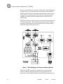
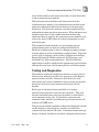
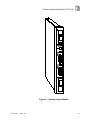
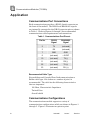
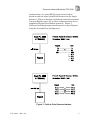
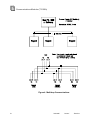
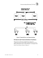
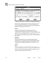
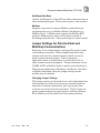
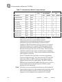
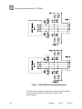
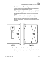
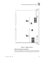
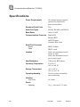
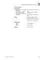
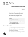
ICS Regent
®
PD-6002
Communications Modules
RS-232, RS-422 and RS-485
(T3150A)
Issue 1, March, 06
Communications modules provide a serial communications
interface between the controller and external equipment.
Communications modules are commonly used to connect the
controller to the computer running the WINTERPRET
application, serial printers, man-machine interfaces,
distributed control system gateways, and other peer-to-peer
controllers.
Features
·
Two isolated serial ports per module.
·
Supports RS-232, RS-422 and RS-485 standards.
•
Regent R2, Guarded Peer-Link, and Modbus protocols.
·
Front panel indicators on each module show communications
status and transmit/receive activity.
·
TÜV certified for safety, Risk Class 5.
Module Operation
A block diagram of a typical communications module is shown
in Figure 1.
Communications modules are serial receiver-transmitters
that provide an electrical interface for RS-232, RS-422, and
RS-485 communications equipment.
Each communications module receives power from all three of
the processor modules. A power-sharing circuit in each of the
communications modules receives the power from the three
Industrial Control Services
1
Communications Modules (T3150A)
processor modules and combines it through a diode OR powersharing circuit. This ensures that if one processor module's
power supply fails, the communications module will continue
to operate by drawing power from the two remaining power
supplies, and the system's communications functions are
maintained.
Additional isolated power converters provide isolated power to
the two serial ports. This isolation provides protection from
external communications cable signal noise and grounding
from affecting module operations.
Figure 1. Block Diagram of Communications Module.
The Dual UART (universal asynchronous receiver/transmitter) buffers incoming and outgoing communications
characters. The triplicated processor modules interrupt once
2
Industrial
Control
Services
Communications Modules (T3150A)
every millisecond to read characters from or write characters
to the communications module.
When the processor modules read characters from the
communications module, the communications module sends
characters through triplicated bus drivers to the processor
Safetybus. The processor modules vote this triplicated data
and perform communications processing. When the processor
modules write data to the communications module, the
triplicated data is voted by the communications modules and
sent to the dual UART where it is then transmitted out the
associated port.
The communications modules’ two serial ports operate
independently and can both be configured differently.
Electrical configuration is done by changing jumper settings
to select point-to-point or multidrop configurations. The ports
can be used to support a wide variety of functions including
Regent R2 protocol, Modbus protocol, ASCII output, and
Guarded Peer-Link communications. The WINTERPRET
application is used to configure the appropriate port functions
and specify baud rate, data format, parity, and node number.
Testing and Diagnostics
The modules triplicated Safetybus interface ensures that no
failure in the module will effect the operation of the Regent
system or other module. Extensive fault detection and
annunciation of critical redundant circuits helps ensure that
processors will not accept erroneous data from a faulty
module.
Each type of communications module has a unique
identification code that is read by the controller. This code
lets the controller know what type of module is installed in
each communications slot. If a module is removed and
replaced with a module of a different type the processors will
indicate a COMM error.
The processor modules perform background diagnostic checks
on the module to test bus driver circuits and check the
communications module ID codes. Communications message
format, framing, checksum, and other communications errors
PD-6002
Mar-06
3
Communications Modules (T3150A)
are checked by the processor modules’ normal
communications processing.
Failures result in a COMM module error indication at the
processor modules and a COMM error at the communications
module.
Front Panel
Figure 2 shows the physical features of the communications
modules. The front panel of each module contains indicators
showing overall module health, and the transmit and receive
status of each channel. In addition to the front panel
indicators, each communications module has two DB-25
connectors (female).
COMM Indicator
This red and green LED pair indicates the overall health of
the module. During normal operation the green LED is on. If
a communications module fault is detected, the red LED turns
on and the green LED turns off.
Transmit/Receive Indicators
These green LEDs are connected directly to the serial signal
lines and flash while data are being transmitted or received.
The TX LED flashes as data are sent from the module, and
the RX LED flashes as data are received by the module.
4
Industrial
Control
Services
Communications Modules (T3150A)
Figure 2. Communications Module.
PD-6002
Mar-06
5
Communications Modules (T3150A)
Application
Communications Port Connections
Each communications port has a DB-25, female connector on
the front of the module. The RS232 and RS422/485 signals
are internally connected to the DB-25 connector pins as shown
in Table 1. Refer to Figures 3 through 5 for recommended
communications cable requirements and connections.
Table 1. Communications Port Pin-out.
Pin No.
RS232
Signal
RS422/485
Signal
2
TX
(not used)
3
RX
(not used)
7
GND
GND
9
(not used)
+ 5 VDC
10
(not used)
TX (-)
11
(not used)
RX (-)
22
(not used)
TX (+)
23
(not used)
RX (+)
Recommended Cable Type
For multidrop and Guarded Peer-Link communications a
Belden cable type 813x (where x = number of pairs) is
recommended. The cable has the following characteristics
that are important:
120 Ohm, Characteristic Impedance
Twisted Pairs
Overall shield
Communications Configurations
The communications module supports a variety of
communications configurations which are shown in Figures 3
through 5. Figure 3 illustrates two point-to-point
6
Industrial
Control
Services
Communications Modules (T3150A)
configurations, one using RS232 connections for short
distances and the other using RS422 connections for longer
distances. Figure 4 illustrates multidrop connections between
2 or more Regents and a PC or other communications device
supporting Regent R2 or Modbus protocols. Figure 5
illustrates multidrop connections between 2 or more Regents
using the Guarded Peer-Link protocol.
Figure 3. Point-to-Point Communications.
PD-6002
Mar-06
7
Communications Modules (T3150A)
Figure 4. Multidrop Communications.
8
Industrial
Control
Services
Communications Modules (T3150A)
Figure 5. Guarded Peer-Link Communications.
Protocols and Communications Functions
The protocol and function supported for each port is
configured using the Serial Ports command from the Project
Editor’s Definitions menu in WINTERPRET. An example of the
Serial Ports dialog is shown in Figure 6.
PD-6002
Mar-06
9
Communications Modules (T3150A)
Figure 6. WINTERPRET’s Serial Ports Configuration Dialog.
The function and protocol for each type of port that you can
select is briefly described below. For more information on
using the Serial Ports command see Section 4, Working with
Projects, in the Regent User’s Guide.
Comm
Supports the Regent R2 protocol for point-to-point
communications between the Regent and the computer
running the WINTERPRET application. Some third-party ManMachine-Interface (MMI) products and DCS gateways may
also support point-to-point communications using the Regent
R2 protocol.
Multidrop
Supports Regent R2 protocol for multidropped Regents
connected to a PC running the WINTERPRET application (or
other third-party supporting products and gateways). Ports
configured for multidrop communications require a node
number.
ASCII
Used by the Regent to transmit ASCII output messages to
external serial equipment such as printers and VDUs. ASCII
output messages are programmed using the ASCII output
element in ladder logic function blocks.
10
Industrial
Control
Services
Communications Modules (T3150A)
Net Master/Net Slave
Used by the Regent for Guarded Peer-Link communications to
other multidrop Regents. These ports require a node number.
Modbus
Supports connection to external Modbus communications
equipment that acts as a Modbus Master (the Regent is a
Modbus Slave). A Modbus port supports the Modbus RTU
protocol. Modbus ports can be used in point-to-point or
multidrop configurations. These ports require a node number.
Jumper Settings for Point-to-Point and
Multidrop Communications
Each port can be independently configured for point-to-point
or multidrop connections. When shipped from the factory,
jumpers on-board the communications module are set for
point-to-point communications. These settings are
appropriate when a single Regent is connected to a PC or
other communications equipment. The port definition can be
COMM, ASCII or Modbus (point-to-point) as described above.
When the port definition is Multidrop, Net Master, Net Slave
or Modbus (multidrop) then the jumper settings on the
module must be changed.
Changing Jumper Settings
The jumper settings on the module are used to determine how
the transmit lines of the serial ports are controlled and also
determine if internal termination, pull-up and pull-down
resistors are connected to the serial lines. Table 2 shows the
proper jumper settings for point-to-point, multidrop (Regent
R2 or Modbus) and Guarded Peer-Link communications.
PD-6002
Mar-06
11
Communications Modules (T3150A)
Table 2. Communication Module Jumper Settings.
Note: n indicates jumper installed
Point-toPoint
Multidrop (Regent
R2 or Modbus)
Description
Port 1
Port 2
End
TX pair terminator
E101
E201
n
RX pair terminator
E102
E202
TX (-) pull-up
E111
E211
RX (-) pull-up
E112
E212
TX (+) pull-down
E121
E221
RX (+) pull-down
E122
E222
Transmit control
E131
E231
Transmit control
E132
E232
Transmit control
E133
E233
n
Middle
n
Guarded PeerLink
End
n
n
n
n
n
n
n
n
n
n
n
n
n
n
n
n
n
Termination, Pull-up and Pull-down Resistor Jumpers
When the module is used for RS422 or RS485
communications, the jumper positions for the internal
termination, pull-up and pull-down resistors must be
considered. Each termination resistor connects an internal
120 Ohm resistor across a specific differential pair and the
pull-up and pull-down resistors connect a 1K Ohm resistor
between each signal line and +5V or Comm. These resistors
should be connected only at the end nodes of the multidrop
communication network. Nodes in the middle should not have
these jumpers connected.
Figure 7 identifies the signal lines, resistors and jumpers
associated with each port. Only the transmit (TX+ and TX-)
and receive (RX+ and RX-) signal pairs are shown. Other
jumpers and resistors for signal pairs CTS, RTS, DTR and
DSR are also located on the module but they are not used by
serial communications for the Regent and their jumper
positions are not important.
Note: If desired, you can install the termination, pull-up and pulldown resisters external to the communications module at the
ends of the multidrop network. In this case position the
jumpers in each communications module for a “middle”
12
Middle
Industrial
Control
Services
Communications Modules (T3150A)
Regent. With each communications module’s jumper settings
the same, module replacement is simpler. A single spare
module can replace any communications module without the
need to position the jumpers specifically for “end” or “middle”
Regents before replacement. Refer to the communications
port pin numbers shown in Figure 7 to determine the proper
external connection of the resistors.
PD-6002
Mar-06
13
Communications Modules (T3150A)
Figure 7. RS422/485 Internal Signal Resistors.
To change the jumper settings the communications module
must be removed from the controller chassis and
disassembled.
14
Industrial
Control
Services
Communications Modules (T3150A)
Module Removal and Disassembly
Using a small slotted screwdriver, loosen the retaining screw
near the top of the communications module.
Pull open both removal levers on the front of the module. The
module will disengage from the controller chassis. When it is
disengaged, carefully slide the module out of the controller
chassis.
With the module removed, use a #2 Phillips screwdriver to
remove the two screws from the left side of the module.
Remove the four Phillips screws from the right side of the
module (see Figure 8). Remove only those screw indicated in
Figure 8.
Figure 8. Communications Module Disassembly.
After removing the screws, separate the printed circuit board
from it protective metal frame.
PD-6002
Mar-06
15
Communications Modules (T3150A)
Refer to Table 2 to identify the proper jumper settings for
your application’s communications configuration. Position
the jumpers as needed on the module. Figure 9 shows the
locations of the jumpers on board the module.
Note: When shipped from the factory, no jumpers are installed on
E131, E132, E133, E231, E232 and E233. For multidrop
configurations you will need two jumpers for each port (such
as E131 and E133 for port 1). The default factory settings
include jumpers positioned at E104, E106, E114, E116, E124,
E126, E204, E206, E214, E216, E224, and E226. These
jumpers connect termination, pull-up and pull-down resistors
for the CTS and DSR signal pairs for port 1 and 2. Since the
CTS and DSR signals are not actually used by the module,
you can remove jumpers installed at any of these positions in
order to install them as needed for E131, E132, E133, E231,
E232 or E233.
16
Industrial
Control
Services
Communications Modules (T3150A)
Figure 9. Jumper Locations.
Module Assembly and Installation
Position the printed circuit board on the metal frame, guiding
the two 96-pin DIN connectors through the slots in the frame.
PD-6002
Mar-06
17
Communications Modules (T3150A)
From the right side of the module, align the four holes in the
printed circuit board wit four metal standoffs. Insert and
tighten the four screws removed from the right side of the
module.
Turn the module over and install the two screws removed from
the left side of the module.
Visually inspect the connector at the back of the
communications module for bent pins. If any pins are bent do
not install the module. Do not try to straighten bent pins.
Return the module to ICS for replacement.
If the pins are in good condition, hold the module with both
hands and open the two module release levers by pulling them
toward you.
Carefully slide the module into the chassis. Be careful to keep
the module aligned while sliding it straight into the chassis.
The module should mount into the chassis with a minimum of
resistance. If the module does not mount easily, do not force
it. Remove it and check it for bent or damaged pins. If the
pins look okay, try reinstalling the module.
When the module is almost fully into the chassis, the release
levers will contact the chassis and begin to rotate closed.
Press the levers closed to seat the module in the chassis.
The top release lever on each communications module is
switched. When the lever is in the open position, the module
is disabled.
If the module does not seem to have seated correctly, open the
release levers and gently pull it back off the seat and out of
the chassis. Check for bent or damaged pins. If the pins look
okay, try reinstalling the module.
After the module is properly seated, tighten the retaining
screw at the top of the module. Fastening the retaining screw
will also help ensure that top (switched) release lever remains
in position.
18
Industrial
Control
Services
Communications Modules (T3150A)
Maintenance
No periodic maintenance or calibration is required for the
digital input modules. There are no user replaceable parts
inside these modules.
Failed modules can be hot replaced. If the module being
replaced has been configured to support multidrop
connections be sure to check the jumper settings and properly
configure the new module’s jumpers before installing it.
Safety Considerations
Communications modules are TÜV certified for Risk Class 5
safety applications as non-interfering and can be used in a
safety system for normal data acquisition functions.
Communications modules are approved for peer-to-peer
communications of safety critical data between two or more
Regent systems in Risk Class 5 safety applications. This
requires the use of redundant Guarded Peer-Link
communications networks where the network connections are
made on redundant communications modules at each Regent.
For additional safety considerations involving
communications with the Regent, refer to the Safety
Considerations Section of the Regent User’s Manual.
PD-6002
Mar-06
19
Communications Modules (T3150A)
Specifications
Power Requirements
No external power required
(powered by triplicated
processor modules)
Number of Serial Ports
Two
Serial Port Types
RS-232, RS-422, and RS-485
Baud Rates
300 to 19,200
Communications Protocols
Regent R2
Modbus RTU
ASCII Output
Guarded Peer-Link
Serial Port Connector
Module:
Cable:
DB-25, female
DB-25, male
Isolation
1000 volts minimum (serial
device to logic)
1000 volts minimum (serial
port to serial port)
Heat Dissipation
7 Watts, 24 BTUs/hour
Operating Temperature
0° to 60° C
(32° to 140° F)
Storage Temperature
-40° to 85° C
(-40° to 185° F)
Operating Humidity
0 to 95% relative humidity,
non-condensing
Vibration
10 to 55 Hz:
±0.15mm
Shock
Operating:
20
15 g, ½ sine wave, 11 msec
Industrial
Control
Services
Communications Modules (T3150A)
Electromagnetic
Interference
•
•
•
IEC 801 Part 2 - Electrostatic
Discharges
IEC 801 Part 3 - Radiated
Electromagnetic Fields
IEC 801 Part 4 - Transients
and Bursts
Safety
Level 3: Contact discharge of
6 kV
Level 3: 10 V/M, 27 MHz 500 MHz
Level 4: 2 kV, 2.5 kHz for t =
60 sec
Certified to DIN V VDE
0801 for Risk Class 5. Also
designed to meet UL 508 and
CSA 22.2, No. 142-M1981
Dimensions
Height:
Width:
Depth:
Weight
PD-6002
Mar-06
13.0" (330 mm)
1.5" (38 mm)
9.0" (229 mm)
3.0 lbs (1.4 kg)
21