1
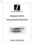
DYNAMOMETER/X-Y
CONTROLLER
MODEL 5230
INSTRUCTION AND
REFERENCE MANUAL
IDENTIFICATION DIAGRAMS
MODEL 5230 FRONT PANEL
MODEL 5230 REAR PANEL
CONTENTS
1.0
2.0
3.0
4.0
5.0
6.0
7.0
8.0
9.0
10.0
11.0
12.0
13.0
13.1
13.2
13.3
13.4
14.0
15.0
Introduction
Connecting Instructions
Operational Checkout
X-Y Recording: General Information
X-Y Recording: Setup and Operation
Automatic Speed Control
Inertial Error Compensation: General Information and Setup
Locked-Rotor Tests
Torque (Control Mode)
External Speed/Torque Control
Test Time
Stability
Description of Torque and Speed Control Circuits
Description of Speed Measuring Circuit
Torque Conditioning Circuit
Description of Test Time Ramp Circuit
Power Supplies
Calibration and System Balancing
Metric and Power Conversions
Schematic Diagrams
Magtrol Limited Warranty
Other Magtrol Products
2
2
2
3
4
4
5
5
6
6
6
6
6
7
7
7
7
7
9
10, 11
12
Back Cover
OPERATING INSTRUCTIONS
SCHEMATIC REFERENCES
1.0 INTRODUCTION
1.1 UNPACKING All shipments leaving our plant are adequately packed and packaged. If there are signs of damage to
this carton or its contents, please notify the shipper within 24 hours and retain carton and packing material for their
examination.
1.2 FEATURES OF THIS MANUAL The inside front cover contains drawings of the front and back panels of Model
5230. For convenience and faster identification, functions appearing on the panels of both controller and readout are
shown throughout this manual in capital letters.
2.0 CONNECTING INSTRUCTIONS
Three pieces of equipment must be interconnected for operation of this Model 5230 controller: a Magtrol load cell
dynamometer, a Model 5420 or 5410 readout, and the 5230 controller.
The Model 5230 controller will additionally provide torque and speed signals to an X-Y recorder or other analog
recording instruments. Information and instructions on this application are given in Sections 4 and 5.
To interconnect the three basic units proceed as follows:
2.1 Connect the 2-pin dynamometer brake cable (part number 88M049) between the dynamometer and the controller.
2.2 Connect and lock the 14-pin cable (part number 88M007) between the readout and the dynamometer.
2.3 Connect the 5-pin “DIN” cable (part number 88M039) between the readout TORQUE-SPEED OUTPUT and the
controller TORQUE-SPEED INPUT.
2.4 Connect the banana plug patch cord (part number 88M002) between the controller TORQUE-SPEED OUTPUTS
and the X-Y recorder inputs.
You are now ready to proceed with equipment checkout and manual operation of the interconnected units.
3.0 OPERATIONAL CHECKOUT
Complete the motor fixturing so that motor and dynamometer shafts are aligned. The means of coupling the shafts
should be angularly flexible and must be torsionally rigid. (Note: Torsionally flexible couplings, such as molded rubber,
should not be used. Because of the high response of the Model 5230 controller, they can induce system instability
resulting in high-frequency shaft oscillation.)
3.1 Set the front panel controls on the controller as follows:
a. BRAKE ON/OFF switch to OFF.
2
b. SPEED RANGE to the first value above the maximum anticipated free-run speed of the motor.
c. SPEED RANGE VERNIER to full clockwise.
d. SPEED (CONTROL MODE) to full clockwise (RANGE MAXIMUM SPEED).
TORQUE (CONTROL MODE) to full counterclockwise (ZERO TORQUE).
e. STABILIZED/OPEN LOOP switch to OPEN LOOP.
f. AUTOMATIC SPEED CONTROL to OFF (illuminating pushbutton dark).
g. TEST TIME to any desired setting.
h. RPM INCREASING/DECREASING to its center neutral position opposite RPM.
i. INERTIAL ERROR COMPENSATION to full counterclockwise (zero on both rotating scales).
j. POWER ON/OFF to ON.
3.2 Start the motor and check to be sure the free-run speed indicated by the tachometer is lower than the SPEED
RANGE setting.
3.3 Switch the BRAKE ON/OFF toggle to ON.
3.4 Slowly rotate the SPEED RANGE VERNIER counterclockwise until the BRAKE energized light goes on. Then
rotate it very slightly until the light just goes out, and leave it at this setting. Note: If the motor speed is less than 1000
RPM, set the vernier at maximum counterclockwise (the BRAKE energized light will not go on).
3.5 Slowly rotate the SPEED control counterclockwise. This causes the dynamometer to load the test motor and the
BRAKE energized light will go on; continuing counterclockwise rotation of the SPEED control will load the motor
down to locked rotor. (Note: In selecting a specific test point of a torque/speed reading, it is usually best to set the
SPEED control at a point lower than the test point, then rotate it clockwise back to the test point. This helps settle the
system and stabilize the test-point value more quickly. Response sluggishness to these adjustments is normal; it is
caused by mechanical inertia and electrical delays.)
4.0 X-Y RECORDING: GENERAL INFORMATION
Two banana plug outputs appear on the rear panel of the Model 5230 controller, ANALOG SPEED and TORQUE. The
red jack on each is positive (+), the black is negative (-) and ground. When connecting an X-Y recorder to the controller,
use either a jumper or shorting bar to connect the recorder ground to either of the controller’s black terminals.
Either axis of an X-Y recorder can be assigned to torque and either to speed, depending on scaling and data presentation.
The analog outputs from the controller are unidirectional and of low impedance. If you wish to reverse the polarity of the
input to either recorder axis, simply reverse the axis input connector from the controller.
4.1 ANALOG SPEED OUTPUT The signal amplitude is 10.00 volts at full scale for each position of the SPEED
RANGE switch. Therefore the precise output voltage (En) for a given speed (RPM) can be calculated from this ratio:
En = 10 RPM
RANGE
(Note: RPM always < SPEED RANGE setting.)
Example for 4-pole 60-Hz motor with free-run speed of 1780 RPM, using the 2(000) position on SPEED RANGE:
En = 10 x 1780 = 8.9 VDC (+1%)
2000
3
(Note: Zero RPM will not be absolute zero volts, since up to + 5 millivolts (.05% fullscale) is possible. This value is
adjustable; refer to paragraph 14.0).
4.2 ANALOG TORQUE OUTPUT The analog torque output (Eq) is proportional to the torque reading of the Model
5420 or 5410 readout. The relationship is as follows (DR represents the readout of all digits, whole or decimal, but with
the decimal point, if any, omitted):
Eq = 4 x DR x 10-3 for standard resolution readout
Eq = 4 x DR x 10-4 for high resolution readout
Example for digital display of 48.2 oz.ft. of torque:
Eq = 4 x 482 x 10-3 = 1.93 VDC (+1%)
As with analog speed output, zero torque is not absolute zero volts. If adjustment is required, refer to paragraph 14.0.
5.0 X-Y RECORDING: SETUP AND OPERATION
5.1 Disconnect any test motor or hardware coupled to the dynamometer shaft.
5.2 Install the calibration beam following the instructions in the dynamometer manual; then using a precision weight
establish a torque value within your range of interest.
5.3 Scale the X-Y recorder for the calibration required.
5.4 With the weight removed, check zero. If the zero has moved, reset it and recalibrate.
5.5 Remove the calibration beam and couple a test motor to the dynamometer.
5.6 With the controller SPEED RANGE set higher than the motor free-run speed, start the motor. Scale the speed axis of
the X-Y recorder to the desired RPM per inch or centimeter excursion.
5.7 Switch the controller’s BRAKE toggle to ON. The BRAKE energized light should be out. Slowly rotate SPEED
RANGE VERNIER counterclockwise until the BRAKE energized light comes on. Then slowly rotate it clockwise
until the light just goes out.
All equipment to record is now set up, and a final, accurate test curve of speed vs. torque can be attempted. But before
doing so, you should become familiar with the four additional functions that appear on the controller: AUTOMATIC
SPEED CONTROL, INERTIAL ERROR COMPENSATION, TEST TIME and STABILITY. They are covered respectively in ections 6, 7, 11 and 12, respectively.
6.0 AUTOMATIC SPEED CONTROL
This control operates in the speed-control mode and performs essentially the same function as the manually adjustable
SPEED control, but it operates more smoothly and repeats automatically.
6.1 Set the TEST TIME to 20 (seconds). This is an average setting. See Section 11 for further information on test times.
6.2 Activate the AUTOMATIC SPEED CONTROL by depressing the red SPEED CONTROL push button (the button
illuminates).
6.3 Set the RPM toggle to DECREASING.
These settings will cause the motor to ramp from free run to locked rotor in approximately 20 seconds. (Note: The
AUTOMATIC SPEED CONTROL can be deactivated at any time by simply pressing the red button again to extinguish
the light. This will return the motor to free run.)
4
6.4 At any load point the RPM toggle can be switched up to INCREASING. This reverses the ramp, causing the speed to
increase at the same rate as it previously decreased.
6.5 To cancel out the ramp and hold the test point, switch the RPM toggle to its center neutral position.
6.6 There is flexibility in the method of controlling the equipment. For example, the RPM toggle can be left in DECREASING and ramp control initiated solely by the red AUTOMATIC SPEED CONTROL button.
7.0 INERTIAL ERROR COMPENSATION: GENERAL INFORMATION AND SETUP
In X-Y recording the motor speed is continually changing. Thus the true torque measurement is the sum of two factors:
the actual turning power of the motor, plus the addition (when decelerating) or subtraction (when accelerating) of the
stored energy in the system (inertia). The inertia factor is proportional to the rate of change of speed and the mass of the
system.
The INERTIAL ERROR COMPENSATION control supplies an adjustable quantity ( mass) of the differentiated speed
signal (differentiation = rate of change). This electrical value is set up as negative in decelerating and positive in accelerating and is summed with the unipolar torque signal.
7.1 Release the lock on the side of the 10 turn dial control by setting it at its up (1 o’clock) position. Then turn the knob
full counterclockwise to the 0.0 position.
7.2 Set up the equipment as in Section 6. Then establish a torque/speed point manually with either the SPEED or the
TORQUE control. When the motor has stabilized and speed is constant, drop the recorder pen to mark this point.
7.3 Return the control to its original position, and using the AUTOMATIC SPEED CONTROL and RPM Decreasing
switch, record a curve around the point obtained manually.
7.4 Return the motor to free run.
7.5 Rotate the INERTIA COMPENSATION control one turn clockwise and repeat the operations in paragraphs 7.2 and
7.3.
7.6 Continue rotating and repeating until the RPM toggle can be switched back and forth from INCREASING to
DECREASING while the curve almost retraces itself. At that stage, the correct setting has been reached.
7.7 When the correct INERTIA COMPENSATION setting has been established, lock it in by setting the lock at its down
(2 o’clock) position. The value will be repeatable for future testing if the mass of the system remains approximately
the same and the same SPEED RANGE is used.
7.8 Typically, leave a slight lead - perhaps around .5 percent higher torque - on the deceleration curve. The magnetic
alignment of the armature to the field is altered upon acceleration or deceleration and, in addition, it is natural for
some rotor heating to occur, resulting in displacement of the retrace curve.
8.0 LOCKED-ROTOR TESTS
To obtain locked-rotor torque as rapidly as possible and with cold-motor performance, the test procedure outlined in
Section 6 should be modified as follows:
8.1 Set the BRAKE ON/OFF switch at ON.
8.2 Set the TORQUE STABILIZED/OPEN LOOP switch at OPEN LOOP.
8.3 Rotate the TORQUE control full clockwise.
8.4 For X-Y data recording, be sure the recorder is on and calibrated and the pen up.
5
8.5 Close the circuit breaker to the motor and immediately drop the recorder pen, then raise the pen and open the circuit
breaker. This takes approximately two seconds. (Note: Because of magnetic slotting effects and bearing friction, most
motors with plain bearings, and to a lesser extent motors with ball bearings, exhibit a range of locked rotor values.
Typically a plain bearing is free only when it has rotation to develop an oil film between shaft and bearing. This range
of locked-rotor values can be as high as 30 percent, depending on the motor.)
9.0 TORQUE (CONTROL MODE)
This is a manual control, its position functioning as follows:
9.1 OPEN LOOP: With the toggle in this position, the TORQUE control regulates current to the dynamometer brake
without feedback reference.
9.2 STABILIZED: With the toggle in this position, the actual torque value is compared with the torque potentiometer
setting, and the current to the dynamometer brake is controlled proportional to the difference. Therefore, the torque is
maintained constant despite any speed changes, temperature changes, or hysteresis effects. (Note: This control is not
useful for locked-rotor tests. A torque signal is necessary for closed-loop operation, and if the test motor is not
energized, there is no torque signal.)
10.0 EXTERNAL SPEED/TORQUE CONTROL
External control of TORQUE and SPEED is provided when an external zero to +5.00 vdc signal is connected through
the Model 5230 rear panel phone connectors. The TORQUE signal is proportional from zero to +5.00 volts DC, no load
torque to full load torque, respectively. The SPEED signal is proportional from zero to +5.00 volts DC, from zero speed
to free run speed, respectively. These signals should be a low source impedance and be capable of sourcing at least 1
milliampere of current, such as an operational amplifier output. When the external TORQUE/SPEED signal is connected, the front panel TORQUE/SPEED control knob is non-functional.
11.0 TEST TIME
Generally, the minimum time a motor is under load beyond the maximum efficiency operating point, the better. But
necessary damping and delays in the data signals limit the speed with which data can be obtained, while still maintaining
accuracy. As a rule of thumb for best results, use a maximum recording time of 1.5 seconds per inch, or .6 seconds per
centimeter. This translates to a TEST TIME setting of 15 or higher for most average conditions, with of course other
settings for special situations.
12.0 STABILITY
System damping is controlled by a locking potentiometer on the rear panel of the controller. The potentiometer should
not be rotated full counterclockwise, which eliminates the rate feedback signal and results in system instability, or full
clockwise, which causes heavy system damping and results in extreme sluggishness. Normally the most desirable
position for critical damping is close to center, with acceptable variance from center depending on the motor/dynamometer combination in use. When adjusting, rotate the potentiometer very slowly.
13.0 DESCRIPTION OF TORQUE AND SPEED CONTROL CIRCUITS
Amplifier U16 is the SPEED control summing amplifier. It receives three inputs to the inverting summing point: speed
analog, rate feedback signal, and the controlled reference.
Amplifier U17 operates essentially identically to amplifier U16 except that its signal sources are an analog proportional
to torque or brake current as selected by the STABILIZED/OPEN LOOP switch.
Amplifier U18 serves the function of automatic biasing off the preamplifier (and subsequently torque) if there is no
speed present on the dynamometer. Automatic biasing is desirable in case the TORQUE control is set for some value
when the motor is off and the switch is in its STABILIZED position. In this situation, it prevents amplifier U17 from
driving the dynamometer brake to full torque.
6
Amplifier U19 is the rate-feedback device essential for the system’s stability. It receives a signal from a 1.0-ohm currentsampling resistor in series with the dynamometer brake. The level of this signal is controlled by the back-panel STABILITY control. The signal is decoupled by two 47MFD tantalum capacitors. Therefore the output is an AC signal in phase,
and proportional to the brake current change. It is applied directly to the summing points of amplifiers U16 and U17.
The outputs of speed amplifier U16, torque amplifier U17 and bias amplifier U18 drive the base circuit of NPN buffer
transistor Q1. Q1’s collector signal turns on the front panel BRAKE-ON indicator LED and provides base current to the
PNP current amplifier transistor Q3. Q3’s amplified collector current flows out through the rear panel BRAKE connector
and through the dynamometer brake coil. This controlled current flow provides speed and torque control to the driving
source connected to the dynamometer’s load shaft.
13.1 DESCRIPTION OF SPEED MEASURING CIRCUIT
The dynamometer speed signal is received through the TORQUE/SPEED 5 pin DIN connector located on the Model
5230 rear panel. Optical coupler U1 isolates and converts the speed signal to a 15-volt logic signal. The speed signal is
shaped by Monostable Multivibrator U2 and passed on to a 4-bit Binary Counter, U3. The Binary Counter is connected
as a 4-bit ripple-through counter. The input count pulses applied to the Binary Counter, U3 pin 14, are simultaneously
divided by 2, 4, 8 and 16. The undivided Binary Counter input pluses (from Monostable U2) are selected by the front
panel SPEED RANGE X 1000 switch for the 2000 RPM range. Also, the divide by 2, 4, 8 and 16 outputs of U3 are
selected by the SPEED RANGE X 1000 switch providing the 4,000; 8,000; 16,000 and 32,000 RPM speed ranges. The
selected speed signal is applied to Frequency to Voltage Converter (F/V) U4. The F/V Converter converts the frequency
signal into a proportional dc voltage. Five calibrated speed ranges result: 2,000; 4,000; 8,000; 16,000 and 32,000 RPM,
with scale factors of 5.000; 2.500; 1.250; 0.625 and 0.3125 volts per kRPM, respectively. The V/F output signal is
conditioned and filtered by amplifiers U5 and U6. This filtered speed signal is connected to Speed Control amplifier U16
to control dynamometer speed (see section 13.0). The speed signal is also buffered by amplifier U7 and output through
the rear panel SPEED/ANALOG OUTPUT banana connector for connection to the X/Y recorder.
13.2 TORQUE CONDITIONING CIRCUIT
The Torque signal from the dynamometer is received through the TORQUE/SPEED 5 pin DIN connector located on the
Model 5230 rear panel. This bi-directional torque signal first passes through an absolute value circuit consisting of
amplifiers U8 and U9. This converts the plus or minus polarity torque signal (+ for clockwise, - for counterclockwise) to
a unidirectional signal (removes the minus sign for counterclockwise torque). The torque signal is then amplified and
inertial error compensation added by amplifier U10. The front panel 10-turn INERTIAL ERROR COMPENSATION
dial sets the amount of added inertial correction. This compensated torque signal is then connected to the Torque Control
amplifier U17 to control dynamometer brake current flow resulting in the control of applied torque (see section 13.0 for
Torque circuit description). Also, the compensated torque signal is buffered by amplifier U11 and output through the rear
panel TORQUE/ANALOG OUTPUT banana connector for connection to the X/Y recorder.
13.3 DESCRIPTION OF TEST TIME RAMP CIRCUIT
Stable 5.00 volts dc from amplifier U12 is applied to an up/down integrator consisting of amplifiers U13 and U14. The
output of U14 is an up/down time ramp set by the Model 5230 front panel TEST TIME-SECONDS switch. Speed timed
ramps from 5 to 40 seconds can be selected.
13.4 POWER SUPPLIES
Power for the controller's operational amplifiers is +15 vdc and -15 vdc supplied by two three-terminal regulator
integrated circuits Q5 and Q6, respectively. Unregulated +75 vdc and +45 vdc are supplied to the output transistors Q1,
Q2 and Q3.
14.0 CALIBRATION AND SYSTEM BALANCING
Normally, the periodic adjustment and calibration of these various electronic elements is unnecessary since minor
alteration in full-scale values and offsets is of no consequence because calibration is performed on the X-Y recorder each
time the equipment is set up.
The following description of the actual function of these adjustments is primarily to assist in understanding their purpose
and the controller’s operation.
7
14.1 Adjust the 5V reference, U12: Connect a DVM between test point TP5 (Op Amp U12 pin 6) and common
(chassis). Adjust the 5v adjust trim potentiometer R47 for 5 vdc + 5 millivolts.
14.2 Calibrate the Torque signal amplifier, U9: Connect a DVM between the TORQUE ANALOG OUTPUT red
terminal and common (black) terminal. Apply (-) 0.500 vdc between pins 4(-) and 3 (+) of the SPEED/TORQUE 5
pin DIN connector located on the rear panel. Adjust the (-) CAL trim potentiometer R33 for (+) 2 vdc + 2 millivolts
on the DVM.
14.3 Calibrate the Torque signal amplifier, U8: With the DVM connected as in step 14.2 above, apply (+)0.5 vdc + 2
millivolts between pins 4(+) and 3(-) of the SPEED/TORQUE 5 pin DIN connector. Adjust the (+)CAL trim
potentiometer R27 for (+)2 vdc + 2 millivolts on the DVM. Disconnect the dc source from pins 4 and 3.
14.4 Zero the Speed voltage/frequency converter, U4: Connect a small solid jumper wire shorting pins 1 and 2 of the
SPEED/TORQUE 5 pin DIN connector. Connect the DVM between TP3 and common. With the DVM set to the
most sensitive scale, adjust the Zero trim potentiometer R22 for zero + 2 millivolts.
14.5 Calibrate the Speed voltage to frequency converter, U4: Preset the Model 5230 front panel SPEED RANGE X
1000 switch to 2 x 1000. Remove the jumper connected in step 14.4 and connect a square wave signal generator, set
for 2000 Hz and switching from ground (zero) and (+)5 volts peak, between pins 2(+) and 1(-). Connect a DVM
between TP4 and common. Adjust the Speed Cal trim potentiometer R8 for (+)10 + 2 millivolts vdc. The other speed
ranges are automatically calibrated when the 2000 RPM range is set. This is true because these higher speed ranges
are an exact digital division of the higher speed.
14.6 Null Speed ripple signal, U5: Connect an oscilloscope to TP4. Set for AC coupling on the most sensitive range
and adjust for a good display of the observed ripple sawtooth. Adjust the Ripple Null trim potentiometer R13 for a
null (minimum peak to peak amplitude) of the observed AC sawtooth waveform.
14.7 Recheck Speed calibration: Repeat step 14.5, readjust if necessary. Disconnect the signal generator.
14.8 Zero Speed output signal, U6: Reconnect the shorting jumper as used in step 14.4. Connect DVM to TP6. Adjust
trim potentiometer R23 for zero + 2 millivolts.
14.9 Balance the test time integrator, U13: Connect DVM to U13 pin 6 (or connector J2 pin 13). Place the Model
5320 into Automatic Speed Control (press Speed Control button - light ON). Activate the RPM-INCREASE/
DECREASE toggle switch so the DVM indicates about 1.0 vdc. Adjust the Ramp Bal trim potentiometer R52 for the
slowest time rate of drift of the DVM voltage reading. Return the RPM-INCREASE/DECREASE switch to its center
position.
14.10 TORQUE CALIBRATION VERIFICATION: TORQUE CALIBRATION can be simply checked by connecting a
MAGTROL calibration beam to the dynamometer shaft (this calibration beam is an option - contact the MAGTROL
Customer Service Department).
Apply rated dynamometer brake current by advancing the Model 5230 front panel TORQUE control knob clockwise.
Verify rated current by inserting a DVM (on appropriate current range) in series with the brake leads. Check that you
have full torque by manually rotating the calibration beam clockwise and counterclockwise. You should feel the applied
torque.
Hang the specified calibrated weight on the calibration beam (see the particular calibration beam and dynamometer
specifications). The weight should freely hang, and the beam should be horizontal as indicated by the bubble level
indicator on the beam.
Connect a DVM to the TORQUE/ANALOG OUTPUT banana connector on the Model 5230 rear panel. Refer to section
4.2 to compute the DVM voltage reading.
8
Note:
If the readout is in High Resolution Mode use:
Eq = 4 x DR x 10-4
To compute the Torque output voltage.
If the readout is in Standard Resolution Mode use:
To compute the Torque output voltage.
Eq = 4 x DR x 10-3
15.0 METRIC AND POWER CONVERSIONS
METRIC
POWER
millimeters x .03937 = inches
millimeters ÷ 25.4 = inches
grams ÷ 28.35 = ounces
kilograms x 2.2046 = pounds
oz.in. x 72.008 = gr.cm.
oz.ft. x .864093 = kg.cm.
lb.in. x 1.15212 = kg.cm.
kg.m. x 9.80665 = N.m (Newton meter)
oz.in. x 7.06155 x 10-3 = N.m (Newton meter)
oz.in. x rpm(9.921 x 10⁻⁷) = hp
oz.in. x rpm(7.401 x 10⁻⁴) = watts
watts ÷ 746 = hp
For further information or technical assistance,
please feel free to contact our Customer Service
Department at any time.
9
MAGTROL LIMITED WARRANTY
Magtrol, Inc., warrants its products to be free from defects in material and workmanship under normal use and
service for a period of 1 year from the date of shipment. Software is warranted to operate in accordance with its
programmed instructions on appropriate Magtrol instruments. This warranty extends only to the original purchaser and shall not apply to fuses, computer media, or any product which, in Magtrol’s sole opinion, has been
subject to misuse, alteration, abuse or abnormal conditions of operation or shipping.
Magtrol’s obligation under this warranty is limited to repair or replacement of a product which is returned to the
factory within the warranty period and is determined, upon examination by Magtrol, to be defective. If Magtrol
determines that the defect or malfunction has been caused by misuse, alteration, abuse or abnormal conditions of
operation or shipping, Magtrol will repair the product and bill the purchaser for the reasonable cost of repair. If
the product is not covered by this warranty, Magtrol will, if requested by purchaser, submit an estimate of the
repair costs before work is started.
To obtain repair service under this warranty purchaser must forward the product (transportation prepaid) and a
description of the malfunction to the factory. The instrument shall be repaired at the factory and returned to
purchaser, transportation prepaid. MAGTROL ASSUMES NO RISK FOR IN-TRANSIT DAMAGE.
THE FOREGOING WARRANTY IS PURCHASER’S SOLE AND EXCLUSIVE REMEDY AND IS IN
LIEU OF ALL OTHER WARRANTIES, EXPRESS OR IMPLIED, INCLUDING BUT NOT LIMITED
TO ANY IMPLIED WARRANTY OR MERCHANTABILITY, OR FITNESS FOR ANY PARTICULAR
PURPOSE OR USE. MAGTROL SHALL NOT BE LIABLE FOR ANY SPECIAL, INDIRECT, INCIDENTAL, OR CONSEQUENTIAL DAMAGES OR LOSS WHETHER IN CONTRACT, TORT OR
OTHERWISE.
CLAIMS
Immediately upon arrival, purchaser shall check the packing container against the enclosed packing list and
shall, within thirty (30) days of arrival, give Magtrol notice of shortages or any nonconformity with the terms of
the order. If purchaser fails to give notice, the delivery shall be deemed to conform with the terms of the order.
The purchaser assumes all risk of loss or damage to products upon delivery by Magtrol to the carrier. If a product
is damaged in transit, PURCHASER MUST FILE ALL CLAIMS FOR DAMAGE WITH THE CARRIER
to obtain compensation. Upon request by purchaser, Magtrol will submit an estimate of the cost to repair shipment damage.
10
MAGTROL PRODUCTS
Motor Analysis and Data
Acquisition
Hysteresis Brakes and
Clutches
Auto Ranging Power
Analyzers
Magtrol dynamometers, considered the
industry standard, range from 2.5 oz.
in. to 250 lb. in. (full scale) for testing
electric, hydraulic and pneumatic motors and gas engines. Magtrol dynamometers provide precise torque loading by means of a hysteresis brake, permitting motor test from zero load to
locked rotor. A variety of controller and
readout options allow for applicationspecific system design. Motor Test
Sofware and data acquisition through
PC integration are also available.
Magtrol pioneered hysteresis brakes
and clutches. These high-precision tension and torque control devices are
"frictionless" and offer significant advantages over magnetic particle and
friction devices, including superior
torque repeatability and accuracy, long
life, low operation costs, smooth operation and broad speed range. Typical applications include: in-process
tensioning for coil winding, labeling,
printing, fiber optic cable, film and
many other material process applications.
Highly accurate single and three phase
power analyzers simultaneously display
true RMS values of volts, amps and
watts of virtually any electrical signal,
DC through 20 kHz. Built-in IEEE-488
interface capability offers extended
functionality through Magtrol Software. Multiple ranges up to 50 amps,
600 volts single phase and 100 amps,
600 volts three phase, with integrating
and power factor measurement capability, plus many other features.
Force Gauges
Superior Force Gauge features
Magtrol's Smart-Cell, precision arbor
press, advanced digital readout, and
WindowsTM-based software. Magtrol's
Smart-Cell is exceptionally sturdy and
designed to provide accurate measurement on and off ram center. The highly
responsive digital readout provides two
programmable set points, peak hold,
RS-232 output and other features.
Available in three sizes with capacities
from 0-5,000 lbs.
70 Gardenville Parkway
Buffalo, New York 14224
716-688-5555
FAX: 716-668-8705