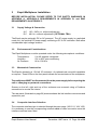
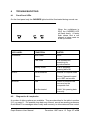
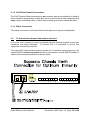
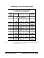
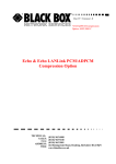
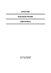
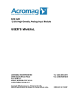
1
ESPRIT
8/16 Channel Statistical Multiplexer
User Manual
WARNING - BEFORE INSTALLATION, PLEASE
REFER TO SAFETY INSTRUCTIONS IN APPENDIX A,
AND EMC INSTRUCTIONS IN APPENDIX C
Certified Compliant in the EC, when fitted in accordance with the installation
instructions, against the following directives/standards:
Low Voltage Directive (73/23/EEC and amendment 93/68/EEC)
EN60950
: 1992 (Safety)
Electromagnetic Compatibility directive (89/336/EEC and subsequent
amendments to date):
EN55022
: 1994 (Emissions)
EN50082-1 : 1992 (Immunity)
Telecommunications Terminal Equipment directive (91/263/EEC and
amendment 93/68/EEC) where indicated in approvals requirements
section.
Part Number: EA 08600B
Esprit Statmux User Manual
December 1997 Issue 1.3 Page 1 of 36
CONTENTS
1
INTRODUCTION
4
1.1
Functional Overview
5
2
USE AND CONFIGURATION
6
2.1
2.2
2.3
2.4
2.5
2.6
2.7
2.8
2.9
2.10
2.11
Data Channel Connection
Default Channel Setup
Changing the Configuration
Supervisor Terminal requirements
Supervisor Terminal Emulations
General Set-Up display layout
General Keyboard Conventions
Composite confiuration
Statmux channel configuration
Copying another channel's set-up
Modem Configuration Options
6
6
6
6
7
8
8
10
10
12
3
INSTALLATION
14
3.1
3.2
3.3
3.4
3.5
3.6
Supply Voltage & Connection
Environmental Considerations
Mechanical Construction
Composite Interface Selection
Composite Connection
Parameter Values
14
14
14
14
15
15
4
TROUBLESHOOTING
17
4.1
4.2
4.3
4.4
Front Panel LEDs
Diagnostics & Loopbacks
Back to Back testing
Statistics
17
17
18
18
Esprit Statmux User Manual
December 1997 Issue 1.3 Page 2 of 36
APPENDICES
A.
B.
C.
D.
E.
F.
G.
H.
Installation Warnings
Approval Requirements
EMC Requirements
Rear Panel Layout
Supervisor Port Pinout V.24 25 Way D Type DCE
Composite Link Interface Pinouts DTE
V.24/V.28 Data Channel Pinout 8 Way RJ45 Type DCE
Composite Link Network Cables
X.21/V.11
X.21bis/V.35
X.21bis/V.24
20
23
24
26
27
28
29
30
31
32
I.
J.
Back to Back Cable
V24 Modem Connections & Setup
33
34
K.
Technical Specification
35
Esprit Statmux User Manual
December 1997 Issue 1.3 Page 3 of 36
Esprit 8/16 Channel
Statistical Multiplexer
User Manual
1
INTRODUCTION
The Esprit is an 8 or 16 channel asynchronous statistical multiplexer, which may be
used with Dial up Modems and Leased lines (such as KiloStream™) up to 256 Kbps in
the case of the 16 channel unit or 64Kbps for the 8 channel.
The unit is easily configured from either end of the link, using a terminal or a PC running
a terminal emulation package.
This user manual covers installation and setup of user options for the multiplexer.
A full set of cable specifications are available in the appendices.
Esprit Statmux User Manual
December 1997 Issue 1.3 Page 4 of 36
Note: Max rate for 8 channel unit is 64K
1.1
Functional overview
The Esprit has 8 or 16 asynchronous ports, and a single composite link which has a
selectable interface type (X.21, V.24 or V.35) .
The composite interface supports synchronous link rates of up to 256Kbps (64Kbps for
the 8 channel unit), either dial up or leased line, for connection to Modems or digital
services such as BT KiloStream™.
The sixteen channel unit will support data rates of up to 115.2Kbps, with a maximum
aggregate of 1843.2Kbps.
The eight channel unit supports rates up to 38.4Kbps with a maximum aggregate of
307.2Kbps.
Unrestricted speed conversions are also possible by setting different data rates at the
local and remote sites.
Esprit Statmux User Manual
December 1997 Issue 1.3 Page 5 of 36
2
USE AND CONFIGURATION
This section covers connection and set-up of the channel data ports. The composite
port is covered in Section 3, the installation section of this manual.
2.1
Data Channel Connection
Peripherals are connected to the V.24/V.28 8-way 'RJ45' type connectors configured
DCE and numbered 1 to 16 (1 to 8) at the rear of the multiplexer. The pin connections
for these data channels are defined in Appendix G.
2.2
Default Channel Setup
When delivered, the Esprit Statistical Multiplexer is set to operate with all channels set
as follows:
Rate
Bits/Char
Stop Bits
Parity
Flow Control
RTS
Mode
2.3
:
:
:
:
:
:
:
9600 bps
8
1
NONE
XOFF
ON
NORMAL
Changing the Configuration
The Esprit may be configured using an asynchronous terminal. A laptop PC running
an asynchronous terminal emulation program such as PCAnywhere™, CrossTalk™ or
Blast™ is ideal for the field engineer.
Windows™ Terminal may also be used to configure an Esprit but please note that
under Settings - Terminal Preferences, the box for 'Use function, arrow and ctrl keys
for Windows' must NOT be set. If it is, then you will not be able to move the cursor
around on the screen.
The terminal should be connected via its serial port to the SUPERVISOR port on the
rear of the multiplexer.
2.4
Supervisor Terminal requirements
The terminal must be configured to:
8 bit character, no parity, one stop bit, speed 9.6Kbps, Xon/Xoff
A suitable cable for connection of the Supervisor port is defined in Appendix E.
Esprit Statmux User Manual
December 1997 Issue 1.3 Page 6 of 36
2.5
Supervisor Terminal Emulations
Several terminal emulations are supported by the Esprit. When connection is made
between the terminal or PC and the rear panel port labelled SUPERVISOR, the
following screen will appear:
Please select terminal type from the following:
1 = VT52
2 = VT100
3 = ADDSVP
4 = ADM3A
5 = H1500
6 = N8009
7 = TVI920
The terminal type or emulation in use should be selected by pressing the relevant
number key on the PC or terminal. The monitor will now show the basic configuration
screen for the multiplexer setup. This is formatted as below (16 channel unit shown):
ESPRIT 16 CHANNEL STATISTICAL MULTIPLEXER
Vx.xx
=====================================================================================
Carrier
Link Clock
Mode
Configuration
:
:
:
:
V.11 PRESENT 64K
EXTERNAL
NORMAL
>LOCAL
Channel
Rate
Bits/Char
Stop Bits
Parity
Flow Control
RTS
Mode
:
:
:
:
:
:
:
:
1
9600
8
1
NONE
XOFF
ON
NORMAL
<= More
2
9600
8
1
NONE
XOFF
ON
NORMAL
3
9600
8
1
NONE
XOFF
ON
NORMAL
4
9600
8
1
NONE
XOFF
ON
NORMAL
Channels 1 - 16
Modem Setup
Statistics
:
:
:
5
9600
8
1
NONE
XOFF
ON
NORMAL
8
9600
8
1
NONE
XOFF
ON
NORMAL
6
9600
8
1
NONE
XOFF
ON
NORMAL
7
9600
8
1
NONE
XOFF
ON
NORMAL
More =>
Cursor Keys to move, CTRL-U to save, ESC to abandon
=====================================================================================
Use <SPACEBAR>/<+>/<-> to select
Esprit Statmux User Manual
December 1997 Issue 1.3 Page 7 of 36
2.6
General Set-Up Display Layout
There are three main areas on the supervisor set-up screen used to change parameters
for the Esprit:
Upper left System parameters (Mode,
Link Clock, Carrier, Residual,
and Configure).
Upper right Other display pages which
may be selected (Channels 1
to 16, Modem Setup.
Bottom Channel configuration.
The initial display is that for the ASYNC channels.
2.7
General Keyboard Conventions
Only a few keys are required to configure the Esprit multiplexer and are summarised
as follows:
(Right arrow)
Moves the cursor to the next field to the right.
(Left arrow)
Moves the cursor to the next field to the left.
(Up arrow)
Moves the cursor to the next field upwards.
(Down arrow)
Moves the cursor to the next field downwards.
+ (Plus) or <SPACEBAR>
Toggles the parameter value up to the next available setting.
- (Minus)
Toggles the parameter value down to the next available setting.
<ENTER> or <RETURN>
Accepts the current display page (else same as ).
<CTRL> and U
Accepts all changes and causes multiplexer re-configuration.
<ESC>
Abandons all changes since last <CTRL> and U.
Esprit Statmux User Manual
December 1997 Issue 1.3 Page 8 of 36
2.7.1 Cursor Movement
The cursor symbol ">" is moved around the screen to the required field using the arrow
keys.
2.7.2 Parameter changing
If it is possible to modify the field over which the cursor is placed, the message "Use
<SPACEBAR>, <+>, <->" is shown at the bottom of the screen. No message will
appear if the field is calculated, un-modifiable or hardware set.
Pressing the Space bar, the "+" key or the "-" key will cycle through the choices
available for a parameter.
2.7.3 Accepting all changes and Updating the configuration
If "Control" and "U" are pressed at the same time after the configuration has been
suitably adjusted, the configuration is updated at the local and remote end as necessary
and held in Non-Volatile Memory (NVRAM.)
2.7.4 Abandoning Changes
Pressing ESC at any point before a configuration is updated will cause the message
Abandon Changes? (y/n) to appear at the bottom of the screen. If n is selected the
message will disappear and editing may continue. If y is pressed, all modifications will
be abandoned and last updated configuration will be re-painted to the screen.
2.7.5 Local or Remote Configuration.
Most settings are independent at each end of the multiplexer link e.g. Flow Control,
and Rate.
The "Configure" parameter in the upper left of the selected screen shows whether the
LOCAL or REMOTE multiplexer is being configured.
2.7.6 Changing the configuration page
The Configuration Page required, e.g. Channels 1-16, or Modem Setup etc., is
selected by moving the cursor to the upper right area and pressing Enter when
alongside the required page.
Esprit Statmux User Manual
December 1997 Issue 1.3 Page 9 of 36
2.8
Composite Configuration
PARAMETER
Carrier
CHOICES
V.24, V.11
Toggle through software
Internal link fitted to J5
V.35
Internal link fitted to J6
Link Clock
2.9
NOTES
If the screen shows either
V.24 or V.11 then you may
toggle between the two
using the space bar.
To select V.35 , the link
fitted to J5 must be moved
to J6
Ext
Normal setting.
INT [Rate]
Internal clock rates of up to
256K may be set for test
purposes.(64K for 8
channel unit)
STATMUX channel Configuration
To change the Statmux channel configuration, select the configuration screen (shown
on page 7) by moving the cursor to the top line on the right hand area of the screen,
next to 'Channels 1-16:' (Channels 1-8) and pressing ENTER or RETURN.
The display shows parameters for eight data channels CH1 to CH8, or CH9 to CH16.
The alternative 8 channels are selected by moving the cursor further to the left or right
as necessary.
Each data channel has parameters selectable as detailed on the following page.
2.10
Copying another channel's set-up
Channel data may be copied from another similar STATMUX channel, by placing the
cursor over the channel number field (of the channel to be changed).
The message 'Enter number or use <+>/<-> to copy channel' appears.
Simply entering the number (if channel is less than 10) of the channel to be copied
transfers all of that channels parameters to the current channel. If the channel number
is greater than 10, the spacebar may be used to increment it through each channel
number.
Esprit Statmux User Manual
December 1997 Issue 1.3 Page 10 of 36
Esprit Channel Set-up Options
PARAMETER
CHOICES
NOTES
1 to 16 (8)
Use spacebar or '-' key to
select another channel to
copy.
0 to 115200 bps. (38400bps
for 8 channel)
Data channel bit rate.
Independently settable at
each end of link.
Bits/Char
5, 6, 7 or 8 bits.
Number of bits per
asynchronous character.
Stop Bits
1, 1.5 or 2
Number of stop bits per
asynchronous character.
EVEN, ODD or NONE
Asynchronous data parity.
XOFF
XOFF - use XON/XOFF soft
flow control
CTS
CTS - Uses DTR (input) to
control data flow out from
MUX, CTS (output) to
control data flow from
equipment to MUX.
NONE
No Flow control used
ON
Always on
OFF
Always off
(DSR)
Transparent to DSR
NORMAL
Normal RUN mode.
ECHO
Data echoed locally and
sent to remote (Half duplex
mode).
LLOOP
Data locally looped back to
this site. Not sent via link.
QBF1
Send Quick Brown Fox
message directly to local
port.
Channel
Rate
Parity
Flow Control
RTS
Mode
Esprit Statmux User Manual
December 1997 Issue 1.3 Page 11 of 36
2.11
QBF2
Send Quick Brown Fox
message via link to remote
port.
LOOP-R
Set this at remote site to
loop back data to local via
link.
Modem Configuration Options
The screen below shows the Modem Configuration options. A modem call is made
when characters are detected in any channel buffer. The call will be dropped
automatically after the period shown as 'Link fallback' after all data has been sent
successfully.
ESPRIT 16 CHANNEL STATISTICAL MULTIPLEXER
Vx.xx
=====================================================================================
Carrier
Link Clock
Mode
Configuration
:
:
:
:
V.24 LOST
EXTERNAL
NORMAL
>LOCAL
Link Fallback :
30 Seconds
Status
Idle
:
Channels 1 - 16
Modem Setup
Statistics
:
:
:
Cursor Keys to move, CTRL-U to save, ESC to abandon
=====================================================================================
Use <SPACEBAR>/<+>/<-> to select
Esprit Modem/External TA Configuration options
PARAMETER
Link Fallback
CHOICES
PERM
Esprit Statmux User Manual
NOTES
LINK permanently
established. Use for leased
line operation.
December 1997 Issue 1.3 Page 12 of 36
Status
30 Seconds, 1 Minute
2 Minutes, 5 Minutes
15 Minutes, 30 Minutes
60 Minutes.
Time before call is
automatically dropped, if no
further data flow detected.
No Options
Gives the current diagnostic
status of the Modem call
progress
Esprit Statmux User Manual
December 1997 Issue 1.3 Page 13 of 36
3
Esprit Multiplexer Installation
BEFORE INSTALLATION, PLEASE REFER TO THE SAFETY WARNINGS IN
APPENDIX A, APPROVALS REQUIREMENTS IN APPENDIX B, and EMC
REQUIREMENTS IN APPENDIX C
3.1
Supply Voltage & Connection
A.C.
D.C.
100 - 240V a.c. without adjustment.
48V d.c. without adjustment. (OPTIONAL TBA)
The Esprit may be optionally DC or AC powered. The AC power supply is a switched
mode unit, the optional DC power supply unit being a DC to DC convertor. Both allow
considerable input voltage variation.
3.2
Environmental Considerations
The Esprit Multiplexer must be operated under the following atmospheric conditions:
Temperature:
Humidity:
Air Pressure:
3.3
0 to 40 degrees centigrade.
0% to 90% non-condensing.
86 to 106 kPa.
Mechanical Construction
The Esprit is housed in a 1.5U tall 19" enclosure. An optional rack mount kit is available
on request. Three LEDs on the front panel indicate the current status of the multiplexer.
The multiplexer MUST be disconnected from the power supply before opening the
unit or changing any network connections.
Screws on the left, right and top of the enclosure are removed using a Pozidrive
screwdriver to access the interior.
The rear panel (illustrated on page 26) accommodates the link interface connectors and
supervisor port.
3.4
Composite Interface Selection
The composite interface type is selected through the menu page. (X21/V11, V24, V35).
It is necessary to use the corresponding external cable to make connection once the
interface card has been fitted.
Esprit Statmux User Manual
December 1997 Issue 1.3 Page 14 of 36
3.5
Composite Network Connection
The Esprit Statistical Multiplexer supports Network Interfaces of X21/V11, V35 and V24.
The composite port appears on the back panel as a 15 way D-type connector, the pinout for each interface standard being shown in Appendix F. Correct cables for Network
connection are shown in Appendix H.
3.6
Composite Link Parameters
Parameters in the System area (upper left) and the choices available by pressing the
Space Bar or + and - keys are:
Esprit Statmux User Manual
December 1997 Issue 1.3 Page 15 of 36
PARAMETER
CHOICES
NOTES
Link Clock
EXTERNAL
INTERNAL 64K
Rate up to 256K can be
set on INTERNAL
V.11/V.24/
V.35
Present
Lost
Shows whether the link
is successfully
connected.
NORMAL
Normal RUN Mode
LLOOP
Loops all transmitted
data to the receiver.
LOCAL
"Modified" appears if
change has been made.
Mode
Configuration
REMOTE
In dial up mode, a call
will automatically be
made when the remote
page is accessed.
Esprit Statmux User Manual
December 1997 Issue 1.3 Page 16 of 36
4
TROUBLESHOOTING
4.1
Front Panel LEDs
On the front panel only the CARRIER light should be illuminated during normal use.
When the multiplexer is
IDLE the CARRIER LED
will flash slowly. A faster
flash shows that a call
attempt is being made on
a dial up modem.
LED LABEL
CONDITION
NOTES
CARRIER
Slow Flash
IDLE
Fast Flash
Call established,
searching for
synchronisation.
Steady Green
Call in progress passing data OK
Not illuminated
Normal un-looped mode
Green
Some Channels looped
or in QBF test modes.
Red
Red if an ERROR has
occurred on the
composite link.
Not illuminated
Unlit if link passing data
correctly.
LOOP
ERROR
4.2
Diagnostics & Loopbacks
A number of debug options are available. They are described in the table in section
2.10, on page 11. It is possible loop back any channel, as well as sending continuous
Quick Brown Fox messages either locally and remotely, to allow data and flow control
Esprit Statmux User Manual
December 1997 Issue 1.3 Page 17 of 36
to be tested for proper operation.
If flow control is properly set, the messages should be received without loss when
attached to a data tester, terminal or printer. In the case of printers, it is essential to
test flow control also under off-line conditions, as many have very large buffers which
can give a misleading indication that flow control is working when it is in fact not ever
requested by the printer.
4.3
Back-to-Back Testing
It is possible to test a pair of Esprits in a back-to-back mode using a cable as described
in Appendix I
First ensure that both multiplxers are set to the same type of composite interface, then
connect the two composite ports using the appropriate cable.
Set one mux to Internal Clock and also select an valid rate for it to run at. Set the other
mux to External clock.
The multiplexers should establish carrier and perform exactly as if connected via a
digital service.
When you have finished any back-to-back testing, always set the clock back to External
as conflict will occur if it is connected to a digital data service.
4.4
Statistics
Below is an example of the Statistics page.
ESPRIT 16 CHANNEL STATISTICAL MULTIPLEXER
Vx.xx
=====================================================================================
Carrier
Link Clock
Mode
Configuration
:
:
:
:
V.11 PRESENT 64K
EXTERNAL
NORMAL
>LOCAL
Frames Sent
Frame Errors
Retransmit
Throughput
:
:
:
:
Carrier Loss
: 0
9415
0
0
3584
Channels 1 - 16
Modem Setup
Statistics
Frames Received
Frame Errors
Retransmit
Throughput
Unnumbered
:
:
:
:
:
:
:
:
11607
0
0
3584
512
Cursor Keys to move, CTRL-U to save, ESC to abandon
=====================================================================================
Use <SPACEBAR>/<+>/<-> to select
Esprit Statmux User Manual
December 1997 Issue 1.3 Page 18 of 36
Frames sent -
Number of frames that have been transmitted across the
composite link.
Frames Errors -
Number of frames that have errored whilst being transmitted.
Retransmit -
Number of retransmit requests received.
Throughput -
Data throughput in bytes/second.
Frames Received- Number of frames that have been received across the composite
link.
Frames Errors -
Number of frames that have errored whilst being received.
Retransmit -
Number of retransmit requests received.
Throughput -
Data throughput in bytes/second.
Unnumbered -
Number of idle frames received.
Carrier Loss -
Number of times that carrier has been lost.
To reset the statistics page type <CTRL> - R
Esprit Statmux User Manual
December 1997 Issue 1.3 Page 19 of 36
APPENDIX A - SAFETY REQUIREMENTS
WARNING:
THIS EQUIPMENT MUST BE EARTHED / GROUNDED
This equipment relies on the EARTH / GROUND
connection to ensure safe operation such that the
user and TELECOM Network are adequately
protected. It must not under any circumstances be
operated without an earth connection, which could
nullify its approval for connection to a network.
WARNING:
INSTALLATION OF EQUIPMENT
Installation of this equipment must only be
performed by suitably trained service personnel.
WARNING:
CONNECTION OF OTHER EQUIPMENT
This equipment allows connection only of suitably
approved equipment to its ports, the safety status
of which are defined below.
SELV Ports:
i)
ii)
iii)
Supervisor port
Composite port
1 to 16 (Channel ports)
The above named ports are classified as SELV (Safety Extra Low
Voltage) in accordance with in Clause 2.3 of EN60950 (BS7002,
IEC950 as applicable), and must only be connected to equipment
which similarly complies with the SELV safety classification.
Esprit Statmux User Manual
December 1997 Issue 1.3 Page 20 of 36
Warnung:
Dieses Gerät Muß an einem Anschluß mit
Schutzleiter betrieben werden.
Zum sicheren Betrieb ist der Anschluß des Gerätes an
Spannungsversorgungen mit Schutzleiter notwendig. Nur so
kann ein optimaler Schutz für Bedienpersonal und
Übertragungseinrichtungen gewährleistet werden. Unter
keinen Umständen darf dieses Gerät ohne Schutzleiter
betrieben werden, da ansonsten die Zulassung für den
Anschluß an Netzen erlischt.
Warnung:
Installation des Gerätes
Die Installation des Gerätes darf nur von entsprechend
ausgebildetem und autorisiertem Personal durchgeführt
werden.
Warnung:
Anschluß von anderen Geräten
Angeschlossen werden dürfen nur Systeme mit
entsprechenden zugelassenen und geeigneten Schnittstellen,
siehe auch nachfolgende Tabelle:
SELV Ports
i)
ii)
iii)
Supervisor Port
Composite port
1 to 16 (Channel Ports)
Die oben aufgeführten Ports sind klassifiziert als SELV (Safety
Extra Low Voltage) in Übereinstimmung mit Absatz 2.3 der
Verordnung EN60950 (BS7002, IEC950 soweit anwendbar), und
dürfen nur zusammen mit Geräten verwendet werden, die dieser
Bestimmung entsprechen.
Esprit Statmux User Manual
December 1997 Issue 1.3 Page 21 of 36
Mise en garde: Cet équipement doit être relié a la terre
Cet équipement doit posséder une prise de terre de manière
à ce que le réseau télécom et ses utilisateurs soient
équitablement protégés. Tout manquement à cette obligation
entraînerait l'annulation de l'autorisation de connexion a un
réseau.
Mise en garde: Installation de l'équipment
L'installation doit être assurée uniquement par des
personnels convenablement formés à ce type de matériel.
Mise en garde: Connexion d'autres équipements
Des équipement complémentaires pourrant être connectés
aux ports de cet équipement à la seule condition que ceux-ci
soient agrées. Les conditions optimales de sécurité pour
toute connexion sont définies ci-dessous:
Ports SELV.
1) port Supervisor
2) port Composite
3) ports pour les canaux 1 à 16
Les ports cités ci-dessous sont classés dans la catégorie SELV
(Safety Extra Low Voltage) conformément à la classe 2.3 de
EN60950 (BS7002, IEC950 applicable) et doivent être connectés
à des équipements répondant à la norme de sécurité SELV.
Esprit Statmux User Manual
December 1997 Issue 1.3 Page 22 of 36
APPENDIX B - APPROVAL REQUIREMENTS
The Esprit MULTIPLEXER carrying the BABT / CE168 assessment symbols and
approval number, is approved for connection to the networks identified in this Appendix
as follows:
X.21/V.11
Throughout Europe (Pan European) to I-CTR2 at data rates up to and including
256Kbps when the composite interface is configured to X.21/V.11 .
Connection must be made using a suitable non-integral interface specific cable, details
of which are provided in Appendix H, page 30. This cable is available from your dealer
using the specified part number.
V.35
Throughout Europe (Pan European) to I-CTR2 at data rates up to and including
256Kbps when the composite interface is configured to V.35 .
Connection must be made using a suitable non-integral interface specific cable, details
of which are provided in Appendix H, page 31. This cable is available from your dealer
using the specified part number.
V.24
Throughout Europe (Pan European) to I-CTR2 at data rates up to and including
19.2Kbps when the composite interface is configured to V.24 .
Connection must be made using a suitable non-integral interface specific cable, details
of which are provided in Appendix H, page 32. This cable is available from your dealer
using the specified part number.
Esprit Statmux User Manual
December 1997 Issue 1.3 Page 23 of 36
APPENDIX C - EMC REQUIREMENTS
To ensure compliance with the EMC directive, some care must be taken to ensure that
the units are installed properly, using suitable cables and connections. The following
must be observed:
C.1
Limitation of Emissions:
C.1.1 'D-Type' Connections
This product relies on the use of screened cables for connection to the 15 way and 25
way 'D-Type' ports. The cables must have the foil or braid screen connected effectively
to the metal headshell to ensure continued compliance. The following headshells are
among those which have been found to provide suitable screen connection:
a)
b)
c)
CINCH
RS
TOBY
25 Way
15 Way
SCH25-K
460-979
MHDTZK-25-K
SCH15-K
454-930
MHDTZK-15-K
The diagram below illustrates an example of a suitable screen connection. Note how
the foil or braid screen is bent back over the 'C' clip to achieve a pressure contact of the
screen against the shell:
It is important to keep the screen to shell connection as short as possible.
Esprit Statmux User Manual
December 1997 Issue 1.3 Page 24 of 36
C.1.2 RJ45 Data Channel Connections
The RJ45 Channel Data connections do not normally require any shielding or ferrite to
meet emissions requirements, unless they are to be connected to other equipment that
does require a shielded cable, in which case suitable precautions should be taken.
C.1.3 Mains Connection
The mains connection is internally filtered and requires no special consideration.
C.2
To Ensure that adequate immunity is achieved:
It is in the user's interest to ensure continued product immunity against mains born
transients, and static discharge. To achieve this, it is important to ensure that
equipment is effectively earthed.
The mains IEC cable provides some protection, but to achieve optimal immunity, the
chassis EARTH screw connection should be connected to a local EARTH busbar or
cabinet frame wherever possible as shown below:
Esprit Statmux User Manual
December 1997 Issue 1.3 Page 25 of 36
APPENDIX D
Rear Panel Layout
The layout of all ports on the rear panel of a 16 channel Esprit multiplexer is shown in
the diagram below, the 8 channel version doesn't have ports 9-16:
Note: Max channel rate of 38.4K for 8 channel Esprit
Esprit Statmux User Manual
December 1997 Issue 1.3 Page 26 of 36
APPENDIX E - Supervisor port pinout
V.24 Supervisor Port Pinout (25 Way D Type Configured DCE)
1
Ground
2
TxD
3
RxD
4
RTS
5
CTS
6
DSR
7
Common
8
DCD
20
DTR
9600bps Operation: The multiplexer requires connections to TxD, RxD and
Common only. The output signals CTS, DSR and DCD are provided for the
terminal if required.
Cable for connection to PC serial port
Signal
Mux
25 way Male
PC Serial Port
25 way Female
PC Serial Port
9 way Female
Ground
1
1
-
TxD
2
2
3
RxD
3
3
2
RTS
4
4
7
CTS
5
5
8
DSR
6
6
6
Common
7
7
5
DCD
8
8
1
DTR
20
20
4
Esprit Statmux User Manual
December 1997 Issue 1.3 Page 27 of 36
APPENDIX F - LINK A 15 way pinout
15 D-Type Composite Interface
Pin Connections (DTE)
15 Way
Mux
Connector
X.21/V11
V.24
(Normal Use)
1
Notes:
V.35
Type at
Connector
PROTECTIVE GROUND
-
8
G
COMMON
COMMON
Common
Return
2
T(A)
TXDa
TXD
Generator
9
T(B)
TXDb
-
Generator
3
C(A)
DTR
DTR
Generator
10
C(B)
-
-
Generator
4
R(A)
RXDa
RXD
Load
11
R(B)
RXDb
-
Load
5
I(A)
DCD
DCD
Load
12
I(B)
-
-
Load
6
S(A)
RXCa
RXC
Load
13
S(B)
RXCb
-
Load
7
X/B(A)
TXCa
TXC
Load
14
X/B(B)
TXCa
-
Load
15
RTS
RTS
-
Generator
1
15 way D-type connector shell and termination as specified in EMC section
Appendix C, on page 24 of this manual.
Esprit Statmux User Manual
December 1997 Issue 1.3 Page 28 of 36
APPENDIX G - V.24 Data Channel Pinout
V.24 Data Channels connectors 1 - 16 (8 Way RJ45 Type Configured DCE)
DATA CHANNEL CONNECTIONS:
Description
DCE - RJ45
Type
Protective Ground
-
-
TxD
6
Load
RxD
5
Generator
RTS
8
Load
CTS
7
Generator
DSR
1
Generator
Common
4
-
DCD
2
Generator
DTR
3
Load
Esprit Statmux User Manual
December 1997 Issue 1.3 Page 29 of 36
APPENDIX H - NETWORK COMPOSITE CABLES
X.21/V.11 STRAIGHT
15 Way Multiplexer Composite DTE
to Network DCE Cable
(P/N BB15019C)
MUX 15 Way Male
Connector
UNC 4/40 Screws
Notes:
V.11 15 Way Male
Connector
M3 Screws2
Type at Connector
(Normal Use)
1
1
SHIELD
-
8
8
G
Common Return
2
2
T(A)
Generator
9
9
T(B)
Generator
3
3
C(A)
Generator
10
10
C(B)
Generator
4
4
R(A)
Load
11
11
R(B)
Load
5
5
I(A)
Load
12
12
I(B)
Load
6
6
S(A)
Load
13
13
S(B)
Load
1
Pin 14 on Mux not Connected
2
V11 Male for connection to NTU must have M3 Screws. Mux end has 4/40 screws
unless National Regulations permit the use of UNC 4/40. Each cable end must be
clearly identifiable.
3
Dashed lines show wires to be twisted pairs.
4
Cable type: Belden 9506, 6 wire twisted pair overall screen (or equivalent).
Maximum length 100 Metres.
5
Connector shell and termination as specified in EMC section Appendix C, on page
24 of this manual.
Esprit Statmux User Manual
December 1997 Issue 1.3 Page 30 of 36
X21bis/V.35 STRAIGHT
15 Way Multiplexer Composite DTE
to Network DCE Cable
(P/N BB08601A)
MUX 15 Way Male
Connector
UNC 4/40 Screws
Notes:
V.35 34 Way MRA Male
Connector
Type at Connector
(Normal Use)
1
A
SHIELD
-
8
B
COMMON
Common Return
2
P
TXDa
Generator
9
S
TXDb
Generator
15
C
RTS
Generator
3
H
DTR
Generator
4
R
RXDa
Load
11
T
RXDb
Load
5
F
DCD
Load
6
V
RXCa
Load
13
X
RXCb
Load
7
Y
TXCa
Load
14
AA
TXCb
Load
1
Dashed lines show wires to be twisted pairs.
2
Cable type: Belden 9507, 7 twisted pair overall screen (or equivalent). Maximum
length 100 Metres.
3
Connector shell and termination as specified in EMC section Appendix C, on page
24 of this manual.
Esprit Statmux User Manual
December 1997 Issue 1.3 Page 31 of 36
X.21bis/V.24 STRAIGHT
15 Way Multiplexer Composite DTE
to Network DCE Cable
(P/N BB08602A)
MUX 15 Way Male
Connector
UNC 4/40 Screws
Notes:
V.24 25 Way Male
Connector
UNC 4/40 Screws
Type at Connector
(Normal Use)
1
1
SHIELD
-
8
7
COMMON
Common Return
2
2
TXD
Generator
15
4
RTS
Generator
3
20
DTR
Generator
4
3
RXD
Load
5
8
DCD
Load
6
17
RXC
Load
7
15
TXC
Load
1
Cable type: Belden 9540, 10 conductors overall screen (or equivalent). Maximum
length 10 Metres.
2
Connector shell and termination as specified in EMC section Appendix C, on page
24 of this manual.
Esprit Statmux User Manual
December 1997 Issue 1.3 Page 32 of 36
APPENDIX I - Back to Back Test Cables
Back to Back cable spec fo X.21/V.11 , V.24 and V.35
Signal Name
15 way D male (Mux A)
15 way D male (Mux B)
Common
8
8
TxDa/RxDa
2
4
TxDb/RxDb
9
11
RxDa/TxDa
4
2
RxDb/TxDb
11
9
Clocka/Xclocka
6&7
6&7
Clockb/Xclockb
13 & 14
13 & 14
Note : Set Mux A to INTERNAL CLOCK and Mux B to EXTERNAL CLOCK
Esprit Statmux User Manual
December 1997 Issue 1.3 Page 33 of 36
APPENDIX J - V24 Modem Connections & Setup
Modem setup example
Not all modems behave identically, but the following generic AT commands are a useful
starting point. One of the two modems must be set up as the Originator and the other
is set up as the Answering modem.
Set the Originator modem up as follows :AT &F0
AT &M2
AT &D2
AT &S1
AT &Z0= tel No
AT &W
Set Defaults
Set SYNCHRONOUS DTR dialling
DTR required for modem to go online
DSR Responds to remote modem
Set telephone number
Save settings
Set the Answering modem up as follows :AT &F0
AT &M1
AT &D0
AT &S1
ATS0=1
AT &W
Set Defaults
Set SYNCHRONOUS mode
Ignore DTR
DSR Responds to remote modem
Set answer to 1 ring
Save settings
Connect the composite link of the local multiplexer to the calling modem and the remote
to the answering modem using an X.21bis/V.24 Straight cable.
Esprit Statmux User Manual
December 1997 Issue 1.3 Page 34 of 36
APPENDIX K - Esprit TECHNICAL SPECIFICATION
ASYNCHRONOUS DATA CHANNELS
Interface:
V.24/V.28 (DCE)
Capacity:
8 or 16 Channels
Data Rates:
0 to 115200bps (0 to38400bps for 8 channel)
Data Format:
5,6,7,8 bit data
Stop Bits:
1, 1½, or 2 stop bits
Data Parity:
EVEN, ODD or NONE
Data Flow Control:
In Band: XON/XOFF(DC1/DC3).
Out Of Band: CTS (Data to Mux), DTR (Data from Mux)
Diagnostics:
Local and Remote Loopbacks. 'Quick Brown Fox' test messages. Echo
Mode
Flags:
RTS may be set ON, OFF or to follow DSR from the Remote mux
COMPOSITE LINK
Interface:
V.11 , V.35 , V.24 (all DTE)
Data Rates:
Up to 256Kbps (64K for V.24 or 8 channel version), Clock Source
Internal or External
Transmission Modes:
HDLC
SUPERVISOR PORT
Interface:
V.24/V.28 (DCE)
Data Rate:
9600bps asynchronous
Data Format:
8 bits, no parity, 1 stop bit
Supported Terminals:
VT52, VT100, ADDSVP, ADM3A, H1500, N8009, TVI920
GENERAL
Front Panel Indicators:
Carrier, Loop, Error.
Dimensions:
434mm x 274mm x 61mm
Weight:
2.6Kg
Environment:
Operating 0-40C, 0-90% humidity non-condensing
Esprit Statmux User Manual
December 1997 Issue 1.3 Page 35 of 36
Power Requirements:
100 - 240V AC , 50 - 60Hz
Esprit Statmux User Manual
December 1997 Issue 1.3 Page 36 of 36