1
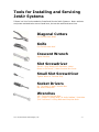
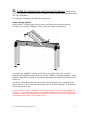
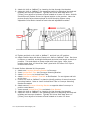
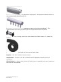
Owner’s Manual Installation and Operating Instructions for JET-1™ Centrifugal Blowers 805-654-7000 805-654-7064 - Fax JetAir Technologies, LLC 1756 Eastman Avenue, #100 Ventura, California 93003 USA [email protected] V1.5.7 Table of Contents JET-1™ Equipment Arrival Equipment Arrival, Inspection, Blower Serial Number Tools for Installation & Servicing 3 3 4 Installation 5 Position Blower Install Air Filter Install Air Components and Connect to Blower Connect Incoming Line Power to the Adjustable Frequency AC Drive Connect the Adjustable AC Drive to the Motor 5 6 7 12 13 Start-Up 16 Service Procedures 18 Start Methods Check Motor Rotation Check Motor Kilowatt Use High Speed Motor Adjustable Frequency AC Drives 16 16 17 18 19 Filter Maintenance 20 Trouble Shooting 21 Important Contact Information 22 Glossary 23 Warranty, Terms & Conditions 24 V1.5.7©2012 JetAir Technologies, LLC -2- Congratulations! All of us at JetAir Technologies are pleased to provide you the most innovative highspeed centrifugal blower available. Our JET-1™ blowers are powerful and extraordinarily reliable. Please take a moment and read through this manual to ensure proper installation and note the safety precautions highlighted in red. You can expect trouble free service by following the instructions in this manual. Equipment Arrival and Inspection Inspect your new blower system at time of receipt to ensure that all components and accessories as noted on the packing slip were received and in good condition. Check to see that the serial number on the packing slip matches the serial number shown on the blower head nameplate. If any equipment was damaged in transit, you will need to make a claim against the freight carrier immediately. If you have any shortages, discrepancies or damage, please call your distributor or JetAir Technologies, LLC at 805 654-7000. Motor Serial Number JetAir Technologies’ blowers have a nameplate on the motor junction box containing the serial number. The motor serial number is located on the top of the motor electrical junction box. V1.5.7©2012 JetAir Technologies, LLC -3- Tools for Installing and Servicing JetAir Systems Follows is a list of tools needed to Install and Service JetAir Systems. Note: ratchets and power assisted tools are not listed here, but can be useful and save time. Diagonal Cutters Cut Flexible Hose Bead Knife Cut Flexible Hose Wall Crescent Wrench Adjust Levelers Slot Screwdriver Slot #2: Open Blower/VFD Enclosure, Maint. Doors on JetTunnel™, Motor Junction Box Cover Small Slot Screwdriver Tighten Wires on Terminal Strip Socket Drivers M7: Terminals in Motor Junction Box M8: Hose Clamp Bolt Wrenches 5/8”: Conveyor Bracket Bolts 1/2”: JetSet™ Locking Bolts, Air Knife/JetBlast™ End Bolts 7/16” JetTunnel™ Ceiling Bolts and Drop-Pan Bolts V1.5.7©2012 JetAir Technologies, LLC -4- Installation Qualified or trained personnel should install the blower. Electrical rotating equipment can result in property damage, serious injury, or death, when improperly installed. Equipment should be installed in accordance with the National Electric Code, local codes, and/or with the “NEMA MG2 Safety Standards for Construction and Guide for Selection, Installation and Use of Electric Motors and Generators”. 1. Position Blower Locate in position where ambient air temperature available for the motor cooling fan does not exceed 90ºF or 32ºC. Blower Systems Blowers not in Enclosures or Part of JetTunnel™ or Premier™ Systems should be positioned by lifting from the motor lifting eye on top of motor or the motor stand. Do not lift the blower by the volute housing. The blower should be located in a place where the blower intake and motor cooling fan are not obstructed and where the filter may be easily serviced. The air intake inlet must be a minimum of 10” or 250mm from the nearest obstruction and the motor cooling fan is a minimum of 2” or 5cm from the nearest obstruction. The blower is designed to rest on its motor stand or enclosure legs. The blower may not be positioned on any other side. Contact JetAir Technologies, LLC for unusual positioning requirements. Bolt your JetAir Technologies blower in place to a rigid floor by the mounting legs. Use a minimum four (4) mounting bolts. Note: The JET-1™ blower weighs ~65lbs. Front View V1.5.7©2012 JetAir Technologies, LLC -5- Side View Enclosed Systems If your blower is installed in an Enclosure, locate and level enclosure and place in location where the blower intake is not obstructed. The air intake, located on the bottom of the enclosure, must be a minimum of 10” (250mm) off the floor and away from any other obstruction. The high vacuum created at the intake can easily aspirate water and debris if the enclosure is less than 10” (250mm) off the floor resulting in a prematurely plugged or saturated filter and subsequent blower damage. Enclosure should be positioned allowing for front panel door swing, easy controls access and an unobstructed air passage for blower outlet on rear of enclosure. JetTunnel™ Systems 2. Install Air Filter Improper filtration or operating the blower without a filter will void the warranty. Canister Filters and Panel Filters are available for JET-1™ JetAir Blowers and JET-1™ Stainless Steel Blower Enclosures respectively for normal operating environments and HEPA applications. Warning: Do not operate blower without filter in place or filter lid unattached V1.5.7©2012 JetAir Technologies, LLC -6- 3. Install Air Components and Connect to Blower. Blower outlet is Ø4” or Ø102mm. Contact JetAir for a variety of valves, hoses, and fittings that may suit your application. For customer installation of a Basic Drying System: Basic™ Drying System JetAir’s Basic™ Drying System are conveyor mounted and incorporate varying numbers of Air Knives, JetBlasts™ and/or other air deliver components. Air Knives and JetBlasts™ can be positioned to dry and/or blow off a variety of products and substrates using JetAir’s Air Knife/ JetBlast™ Mounting Brackets. These brackets allow almost infinite air component adjustment for exact and efficient use of blower air. Typically Air Component Mounts are used for side mounting of air components (as shown above) or for surface mounting where the Air Knife or JetBlast™ is positioned across the conveyor belt. Do not install Air Knife or JetBlast™ Mounting Brackets on conveyors while belts are moving. Conveyor Belts are moving mechanical hazards that can cause bodily harm and death. Use proper safeguards and lock-out procedures to ensure no mechanical movement of belt while you are working on it. V1.5.7©2012 JetAir Technologies, LLC -7- JetAir Air Knife or JetBlast™ Conveyor Mounting Bracket (when attaching directly to conveyor NOT for Premier™ or JetTunnel™) End Bracket Inlet Bracket Vertical Bent Tubes Conveyor Mounting B rackets Air Knife or JetBlast™ Conveyor Mounting Brackets: End/End (used when inlet is in body of knife): p/n Ø2” Inlet/End: p/n Ø2” Inlet/Ø2” Inlet: p/n Ø3” Inlet/End: p/n Ø3” Inlet/Ø3” Inlet: p/n Ø4” Inlet/End: p/n Ø4” Inlet/Ø4” Inlet: p/n MNT-E-CONV-HH MNT-I2-CONV-HH MNT-D2-CONV-HH MNT-I3-CONV-HH MNT-D3-CONV-HH MNT-I4-CONV-HH MNT-D4-CONV-HH To install Side Mounted Air Components: 1. Attach one Conveyor Mounting Bracket to Conveyor. 2. Insert Vertical Bent Tube into Conveyor Mounting Bracket. 3. Attach End Bracket to Vertical Bent Tube. 4. Attach AirKnife or JetBlast™ End Bolt to End Bracket. Do not tighten end bolt at this time. 5. Position Air Knife or JetBlast™ by hand to identify position of second conveyor mounting bracket. Raise or lower Vertical Bent Tube in Conveyor Mounting Bracket as needed. 6. Attach second Conveyor Mounting Bracket in position noted above. 7. Insert second Vertical Bent Tube and attach Inlet Bracket. V1.5.7©2012 JetAir Technologies, LLC -8- 8. Attach Air Knife or JetBlast™ by inserting its inlet through inlet bracket. 9. Adjust Air Knife or JetBlast™ into operating position by adjusting inlet and end brackets and conveyor brackets. Typically Air Knives work best when <1” [25mm] from object to be blown-off and rotated on its axis 15º down. AirKnife should blow-off product first at its highest location on the product. Note: the picture directly below shows optional Air Knife Mounting System using Adjustable Cross Blocks instead of bent tube and adjustable brackets. 10. Tighten end bolt on Air Knife or JetBlast™ and lock into 15º position. 11. Attach Flexible Hose with Hose Clamp to Air Knife or JetBlast™ Inlet. Run hose to Blower or manifold, avoid tight bends and minimize hose length as much as possible. Trim and attach to blower outlet with hose clamp. Note: hose lengths longer than 10’ should be “hard” piped with SS Tube or PVC Pipe to minimize line friction. To install Surface Mounted Air Components: 1. Attach one Conveyor Mounting Bracket to Conveyor. 2. Insert Vertical Bent Tube into Conveyor Mounting Bracket. 3. Attach End Bracket to Vertical Bent Tube. 4. Attach AirKnife or JetBlast™ End Bolt to End Bracket. Do not tighten end bolt at this time. 5. Position Air Knife or JetBlast™ by hand to identify position of second conveyor mounting bracket. Raise or lower Vertical Bent Tube in Conveyor Mounting Bracket as needed. 6. Attach second Conveyor Mounting Bracket on opposite side of conveyor in position noted above. 7. Insert second Vertical Bent Tube and attach Inlet Bracket. 8. Attach Air Knife or JetBlast™ by inserting its inlet through inlet bracket. 9. Adjust Air Knife or JetBlast™ into operating position by adjusting inlet and end brackets and conveyor brackets. Typically Air Knives work best when <1” [25mm] from object to be blown-off and rotated on its axis 15º down. V1.5.7©2012 JetAir Technologies, LLC -9- Line Direction 10. Tighten end bolt on Air Knife or JetBlast™ and lock into 15º position. 11. Attach Flexible Hose with Hose Clamp to Air Knife or JetBlast™ Inlet. Run hose to Blower or manifold, avoid tight bends and minimize hose length as much as possible. Trim and attach to blower outlet with hose clamp. Note: hose lengths longer than 10’ should be “hard” piped with SS Tube or PVC Pipe to minimize line friction. Air Knife or JetBlast™ JetLine™ Mounting Brackets: End/End (used when inlet is in body of knife): p/n Ø2” Inlet/End: p/n Ø2” Inlet/Ø2” Inlet: p/n Ø3” Inlet/End: p/n Ø3” Inlet/Ø3” Inlet: p/n Ø4” Inlet/End: p/n Ø4” Inlet/Ø4” Inlet: p/n MNT-E-JSET-HH MNT-I2-JSET-HH MNT-D2-JSET-HH MNT-I3-JSET-HH MNT-D3-JSET-HH MNT-I4-JSET-HH MNT-D4-JSET-HH To install Side Mounted Air Components in Permier™ or JetTunnel™: 1. Insert Vertical Bent Tube into JetSet™ Bracket. 2. Attach End Bracket to Vertical Bent Tube. 3. Attach AirKnife or JetBlast™ End Bolt to End Bracket. Do not tighten end bolt at this time. 4. Position Air Knife or JetBlast™ by hand to identify position of second conveyor mounting bracket. Raise or lower Vertical Bent Tube in Conveyor Mounting Bracket as needed. 5. Insert second Vertical Bent Tube and attach Inlet Bracket. 6. Attach Air Knife or JetBlast™ by inserting its inlet through inlet bracket. 7. Adjust Air Knife or JetBlast™ into operating position by adjusting inlet and end brackets and conveyor brackets. Typically Air Knives work best when <1” [25mm] from object to be blown-off and rotated on its axis 15º down. AirKnife should blow-off product first at its highest location on the product. V1.5.7©2012 JetAir Technologies, LLC - 10 - Line Direction 15º JetSet™ Mounting Shown without Premier™ or JetTunnel™ System. 8. Tighten end bolt on Air Knife or JetBlast™ and lock into 15º position. 9. Attach Flexible Hose with Hose Clamp to Air Knife or JetBlast™ Inlet. Run hose to Blower or manifold, avoid tight bends and minimize hose length as much as possible. Trim and attach to blower outlet with hose clamp. Note: hose lengths longer than 10’ should be “hard” piped with SS Tube or PVC Pipe to minimize line friction. Manifolds/Dividers: Multi-Y Divider – Aero High-Flow Poly DesignØ3/Ø4” Inlet x (2) Ø2/3/4” Outlets: Multi-Tri Divider – Aero High-Flow Poly Design Ø3/Ø4” Inlet x (2) Ø2/3” + Ø2/3/4” Outlets Multi-Quad Divider – Aero High-Flow Poly Ø3/Ø4” Inlet x (4) Ø2/3” Outlets V1.5.7©2012 JetAir Technologies, LLC p/n FIT-Y-PE-MULT p/n FIT-TRI-PE-MULT p/n FIT-QUAD-PE-MULT - 11 - 4. Connect Incoming Line Power to the PowerFlex 40 Adjustable Frequency AC Drive Only use a qualified electrician and follow all applicable electrical codes. Refer to the AC drive nameplate for correct power supply requirements. Based on the drive nameplate refer to the included Adjustable Frequency AC Drive User Manual for all input and output wiring specifications. Be sure to follow all “General Precautions”, “AC Supply Source Considerations”, and “Input Power Conditioning” Sections found in the Manual, otherwise product life may be shortened and the warranty may be voided. Basic Connection Parameters: a. Connects 3 Phase AC Power + Ground from Line Power to AC Drive b. Consult AC Drive Manual for input power quality requirements c. Input Power is dependent on AC Drive HP requirements – see AC Drive specification d. Wire Gage – AWG is dependent on local code and/or NEC tables and is the responsibility of the customer to specify, procure, and install. e. The customer is responsible for supplying stable and clean incoming power. Depending on quality of incoming power, the customer may be responsible for installing a Line Reactor or other power conditioning equipment to protect the AC Drive. f. “Delta Ungrounded” line power requires a Line Reactor ATTENTION: National Codes and standards (NEC, VDE, BSI, etc.) and local codes outline provisions for safely installing electrical equipment. Installation must comply V1.5.7©2012 JetAir Technologies, LLC - 12 - with specifications regarding wire types, conductor sizes, branch circuit protection and disconnect devices. Failure to do so may result in personal injury and/or equipment damage. ATTENTION: To avoid a possible shock hazard caused by induced voltages, unused wires in the conduit must be grounded at both ends. For the same reason, if a drive sharing a conduit is being serviced or installed; all drives using this conduit should be disabled. This will help minimize the possible shock hazard from “cross coupled” power leads. The PowerFlex 40 AC Drive User Manual is available online at: http://literature.rockwellautomation.com/idc/groups/literature/documents/um/22bum001_-en-e.pdf For IP66 Washdown Drives or Panel Mount Drives located within customer’s electrical For JetAir Factory Enclosed Systems, incoming wire is designed to be brought through a side wall of the enclosure. Use only a qualified electrician to pierce the enclosure wall and route incoming power to the disconnect inside JetAir’s Blower/AC DRIVE Enclosed Systems. Enclosed systems have factory wired connections to AC DRIVE and Motor. 5. Connect the Adjustable Frequency AC Drive to the Motor Basic Connection Parameters: 1. Connects 3 Phase AC Power + Ground from AC Drive to Blower Motor 2. 1 Signal Wire Pair for Motor Thermal Protection circuit 3. Maximum Distance between Drive and Motor: 12m, 40ft 4. Cable Specification: a. Wire Gage - AWG is dependent on local or NEC specifications b. Power Cable must be of VFD Quality – e.g. Lapp - Olflex PN 7410044 or equivalent – contact JetAir for VFD cable detailed specification for your application. 5. Power cable shield to be grounded at both ends: Motor and AC Drive 6. Signal Wire Pair (18-22 AWG) must be connected between the Motor Thermal Protection Switch in motor j-box and a ‘Fault’ digital input on the AC Drive (contact JetAir for instructions if not preconfigured). 7. Failure to install proper cable or connect motor thermal switch voids warranty. WARNING: The JET-1™ motor is a special ‘high-speed’ motor that is matched specifically to the JetAir supplied Adjustable Frequency AC Drive (i.e., frequency inverter or variable frequency drive) shipped with the motor. The motor must always be powered and controlled by the JetAir supplied Adjustable Frequency AC Drive. Use of any other AC Drive, other than the one supplied with the motor, voids warranty. DO NOT, under any circumstance, bypass the AC Drive and connect the JET-1™ high speed motor directly to line power. This will void the warranty and will destroy the motor. Use only a qualified electrician only to make all connections. V1.5.7©2012 JetAir Technologies, LLC - 13 - Note that the Jet-1 Blower Motor is configured to run in Wye for all Jet-1 applications: 5, 7.5, and 10HP. PowerFlex 40 Output Power and Motor Thermal Protection Switch Connections to Jet-1 Motor Junction Box V1.5.7©2012 JetAir Technologies, LLC - 14 - Basic Connection Parameters – AC Drive to Motor: 8. Connects 3 Phase AC Power + Ground from AC Drive to Blower Motor 9. 1 Signal Wire Pair for Motor Thermal Protection circuit 10. Maximum Distance between Drive and Motor: 12m, 40ft 11. Cable Specification: a. Wire Gage - AWG is dependent on local or NEC specifications b. AC Drive to motor power cable must be of VFD Quality (e.g. Lapp Olflex PN 761004 (10AWG x 4C) or equivalent) – contact JetAir for VFD cable detailed specification for your application. 12. Power cable shield to be grounded at both ends: Motor and AC Drive 13. Signal Wire Pair (18-22 AWG) must be connected between the Motor Thermal Protection Switch in motor j-box and a ‘Fault’ digital input on the AC Drive (contact JetAir for instructions if not preconfigured). 14. Failure to install proper cable or connect motor thermal switch voids warranty. Connect customer supplied VFD Grade Cable (consult local electrical codes for proper AWG - wire gage) between the Adjustable Frequency AC Drive and JetAir Blower Motor as indicated in the diagram below. Consult the Allen Bradley ‘PowerFlex Adjustable Frequency AC Drive User Manual’ included with the drive for specific information about motor lead lengths, device protection, grounding, and general wiring recommendations. Note in wiring diagram above that V1 is wired to T3 and W1 is wired to T2 in order to achieve proper counter clockwise impeller rotation. However, motor (impeller) rotation must be visually verified – see next section ‘Start Up’ in the event motor phases are not sequenced as shown. Note: Motor Lead Length between AC Drive and Motor Not to Exceed 40’ (12m) – (Note: Call JetAir if Motor Lead Length is Greater Than 40’) Always use a qualified electrician and follow all applicable electrical codes. Connect a twisted pair of control wires (20 – 24 AWG) from the Motor Thermal Protection Switch to terminals No. 8 and 11 on the AC Drive. This is a normally closed circuit (N.C.) that will open when motor winding temperatures exceed a safe limit and generate an ‘Aux Fault’ in the AC Drive (shutting the drive and blower down). When temperatures drop to a safe level, the switch closes. Note all drive faults must be manually cleared before the drive will restart. It is important that the Motor Thermal Protection Switch is wired and configured in the AC Drive to protect the motor. Not wiring the switch to the AC Drive will void the warranty on the motor. Note and follow all Safety Precautions and Warnings. Unauthorized customer programming of the Adjustable Frequency AC Drive voids drive warranty. Never reset the AC Drive to defaults using the ‘Reset to Defaults’ feature under any circumstances without contacting JetAir first for approval – Default Nameplate parameters will do irreparable harm to the motor. V1.5.7©2012 JetAir Technologies, LLC - 15 - Start-Up Wear safety glasses and earplugs when working on the blower system, airknife, or discharge nozzles of your JetAir Technologies Blower System. WARNING: The Adjustable Frequency AC Drive maybe programmed to automatically start the when line power is turned on to the Adjustable Frequency AC Drive. In this case, the blower will start and accelerate to the programmed speed as specified for your application. If you are not sure of the configuration, please contact JetAir Technical Support at 805-654-7000. 1. Start Methods Following proper connection of line power to the AC Drive and from the AC Drive to the Blower Motor the blower is ready to start. Specific methods to Start and Stop the blower may vary depending on the application. Typical start configurations include: A. B. C. D. E. Start Start Start Start Start / / / / / Stop Stop Stop Stop Stop blower blower blower blower blower when power is applied or removed from the AC Drive using enclosure mounted ‘on-off-auto’ switch by using HIM keypad on Drive or Enclosure Door using AC Drive installed Comm Card using customer PLC Frequent Start / Stop Warning: Contact JetAir immediately if you application requires the blower to start / stop more than 3 times / hour as this requires an idle speed option to keep the blower motor from overheating. Consult the PowerFlex 40 AC Drive Parameter listing provided and programmed into your AC Drive. Consult the PowerFlex 40 User Manual for a comprehensive list of all input wiring options for drive and speed control. The Start method and associated parameters were entered and tested with your Blower by JetAir prior to shipment. The AC Drive configured with the blower is normally preprogrammed by JetAir to start and accelerate to your specific operating speed in 30 seconds (acceleration times may vary depending on application requirements). If you have any questions about your configuration or wish to change control parameters, please contact JetAir for assistance. Changing factory programmed parameters or ‘resetting to defaults’ without consulting JetAir may result in permanent damage to the AC Drive and Blower and may void your warranty. 2. Check Motor Rotation The blower should be rotating counter-clockwise while looking from the impeller side of the blower. Check this by ‘bumping’ the motor using the Start command from the blower and observing the rotation. Rotation of the cooling fan on the rear of the motor may also be used. Note that correct rotation of the cooling fan is ‘clockwise’ V1.5.7©2012 JetAir Technologies, LLC - 16 - Impeller rotation must be counter clockwise as indicated on the volute as viewed from the front intake side. The blower must rotate counter-clockwise when viewed from the impeller or intake side of the blower (see diagram next page). Check rotation by ‘bumping’ the motor for a few seconds using the Start command from the blower and then observing the impeller rotation. Rotation of the cooling fan on the rear of the motor may also be used in the event the intake side of the blower cannot be observed due to mechanical restrictions. Note that correct rotation of the cooling fan is ‘clockwise’ when viewed from the backside of the motor. Correct motor rotation provides optimum performance. However, substantial flow and pressure will still be achieved when running backwards despite significant efficiency loss. Backwards impeller rotation will also cause additional damaging vibration on highspeed motor. Backwards running of blower will invalidate warranty. If impeller rotation is clockwise (incorrect), then change to counter clockwise (correct) by switching input power leads from the Adjustable Frequency AC Drive to the motor on terminals V1 and U1 in the motor junction box (see diagram next page). Note: switching incoming (i.e., line) power leads to the Drive will not affect motor rotation. 3. Connect Air Components & Filter / Check kilowatt Use Prior to checking power consumption and running the blower at operating speed make sure all intake and exhaust plumbing connections are in place. Higher than expected kilowatt or horsepower usage beyond drive rating may generate a Hardware OverCurrent fault. On a new installation this typically indicates excess flow as a result of an ‘open’ system not connected to air components on the intake and exhaust: hose, valves, dividers, and/or air knifes. V1.5.7©2012 JetAir Technologies, LLC - 17 - Service Procedures Wear safety glasses and earplugs when working on the blower system, Airknife, JetBlast™, or any other discharge nozzles of your JetAir Technologies Blower System. Follow all National, State, Local, and Company codes and policies when disconnecting the electrical power at the motor, junction box, fuse box or circuit breaker before working on your system. Take special precautions to make sure that power cannot be turned on while you are working on the blower. Use an approved lock out / tag out system. Review Adjustable Frequency AC Drives Safety Precautions in User Manual. Note: Adjustable Frequency AC Drives can retain an electrical charge for up to three minutes after disconnecting power. Blower units that are damaged and unable to run because of overheated motor, impeller damage, impeller non-rotation or other problem must be factory serviced. See Warranty and Terms & Conditions at the end of this document for information on making a warranty claim. JetAir’s return address is: JetAir Technologies, LLC 1756 Eastman Avenue, #100 Ventura, California 93003 USA Attn: Returns (RA No. ------) JET-1™ Blowers are designed for easy replacement and reinstallation. Prior to factory shipment back to JetAir you need to place motor-impeller assembly into a secure container for shipment to JetAir Technologies. Returns damaged due to poor packaging will void the warranty. JetAir must issue a Return Merchandise Authorization Number (RA) prior to accepting any return per the terms and conditions detailed at the end of this document. Shipments without an RA number will be refused. 1. High Speed motor JetAir Technologies blowers employ a special high speed motor and have an extended life when operated under normal conditions. Each motor is ultra-balanced at the factory for high-speed operation and do not need periodic re-lubrication. Motors should be bolted to a secure non-vibrating surface or platform. Vibration pads are not necessary unless there is a need to dampen outside or non-blower induced vibration. Motor Operating altitudes are Sea Level to 3300 feet or 1000M. Motor Operating Ambient Temperatures are –25ºC to 40ºC Misapplication of a motor in a hazardous environment can cause fire or an explosion and result in serious injury or death. V1.5.7©2012 JetAir Technologies, LLC - 18 - Only the end user and/or insurance underwriter are qualified to identify the appropriate use of JetAir Technologies’ motors. Certifications: UL, CSA, and CE. Motors built in ISO9000 certified locations. Always use qualified personnel and follow safety laws and standards when working with electrical equipment. 2. Adjustable Frequency AC Drive Rockwell Automation’s PowerFlex 40 AC Drives are designed to protect the motor and provide variable power and frequency to drive JetAir high speed blower motors. The PowerFlex 40 is a feature rich drive that enables specific programming to optimize blower performance while maximizing electrical efficiency. PowerFlex 40 AC Drives for the Jet-1 Blower are available in 200V Class (190-240V), 400V Class (380-480V) and 600V Class (430-600V), 50 or 60Hz applications, and in IP66-NEMA4 or IP20-NEMA12 versions. Consult the ‘PowerFlex 40 AC Drive User Manual’ for specific environmental operating specifications and cabling recommendations. The manual is available online at: http://literature.rockwellautomation.com/idc/groups/literature/documents/um/22bum001_-en-e.pdf Custom Programming and PLC communications modules are available. Contact JetAir Technologies for consultation and factory programming. Unauthorized customer programming of the Adjustable Frequency AC Drive voids drive warranty. Do Not ‘Reset to Defaults’ under any circumstances without contacting JetAir first for approval – Default name plate parameters will do irreparable harm to the motor. Certifications: UL, CSA, C-Tick and CE. See Typical Drive Parameter Listing for the PowerFlex 40 AC Drive on the Next Page. Your specific drive parameters may vary from those listed depending on the HP and air components attached to the blower. Please contact JetAir prior to changing any parameters on the drive. V1.5.7©2012 JetAir Technologies, LLC - 19 - Filter Maintenance General Recommendations JetAir Technologies’ Air Filters are inexpensive and easy to change. Filters should be changed based on the maintenance schedule below at a minimum or when inlet Filter Change Gage indicator needle moving from the green to red zone. Customers in unusual environments and special situations may need to change filters more frequently. Remember to routinely maintain or change blower intake filters as the blower warranty is voided if a blower is operated without a filter or improperly maintained filter. Filter Maintenance Schedule Filtration is critical to performance, longevity, and enforcing the warranty on JetAir Industrial Blower Systems. The following are general guidelines for standard polyester canister filter replacements in various commercial environments. Request a JetAir sales engineer for specific guidelines for your application and environment: Beverage – Beverage – Industrial Industrial – Textile - Soda and Juices Beer Oil Mist Dust Fabric debris 30 days 60 days 60 days 90 days 120 days Canister Filter Change Procedure 1. Change filter by removing the top filter cover knob. Then remove the filter cover and remove the used filter off. Reverse process to install new filter. (See page 4.) Panel Filter Change Procedure for Stainless Steel Enclosure: 1. Change filter by opening the door of the blower enclosure and remove old filter. Slide new filter into position along guide rails near the top of the enclosure. Note air flow direction arrow on the side of the panel air filter. Correct air flow is from the top of the enclosure down into the blower compartment. 2. Make sure the access door is closed and securely fastened. 3. Inspect enclosure at blower outtake and make sure outtake gasket is in place between the enclosure wall and blower outtake. This seal assures no air will bypass the filter into the blower compartment. Canister Replacement Filters: Filter Assy – Hi-Flow Paper Element Filter Element – Hi-Flow Paper Element p/n FILT-A-J1-PAP p/n FILT-J1-PAP Panel Filter Element Replacement: Filter Element - Hi-Flow Synthetic p/n FILT-ENC-HYN Need a filter? Call us. We stock for immediate delivery. 805-654-7000 or [email protected] © 2013 JetAir Technologies, LLC Rev 01162013 Trouble Shooting Your JetAir Technologies blower is designed to operate reliably. Here are some trouble shooting observations that have helped others. Blower Does Not Start Top Line of HIM Display Not Showing “Fault”, but Displays “Not-Enabled” • Check Panic Stop Button • Check Safety Interlocks if in use. Blower Does Not Start Top Line of HIM Display Not Showing “Fault”, but Displays “Stopped” Typically occurs when system is setup to start automatically when power is applied. System is stopped because a STOP is invoked. • Check Selector, turn to ON • Cycle power • Check Parameters Blower Begins to Start, but Hz do not change but Amps increase slightly. Low Flow, Pressure or Vacuum, Amps are lower than expected Irregular Noise © 2013 JetAir Technologies, LLC Rev 01162013 This condition may also occur when Selector is turned to Auto and remote customer PLC switch is open. • Check Remote Switch • Check Selector, turn to AUTO • Check AC DRIVE Terminal Strip: • Check Parameters • Check Motor to AC DRIVE wiring indicative of 2-phase wiring on 3 phase system. This means that one power input is missing or loose connection. Check for tight connections on power leads to motor on motor and drive sides. • Impeller is rotating backwards. Correct Rotation is counterclockwise when looking at intake impeller. Change impeller rotation by switching any two power leads between Motor and AC DRIVE. • Dirty Filter. • Collapsed Flex Hose or Piping. • Damaged Impeller. • Closed Butterfly Valve. • Undersized Piping/Hose volume. • Air Leakage. • Loose V-Clamp. • Blockages or Restrictions on intake or outlet sides of blower • Leakage in piping. • Cracked hoses. • Loose bolts on mounts. • Vibrations from other machines. • Blocked Intake or Exhaust Important Contact Information JetAir Technologies, LLC: Technical Support: Sales: 805-654-7000 main; 805-654-4064 facsimile [email protected] [email protected] PowerFlex 40 Adjustable Frequency AC Drive Reference Manual – is more comprehensive than the User Manual and is available online as a .pdf file at: http://literature.rockwellautomation.com/idc/groups/literature/documents/um/22bum001_-en-e.pdf. Complete Rockwell Automation Literature Library - including all support documentation and recommendations for the PowerFlex 40 (under ‘Drives’ ) is available at: http://literature.rockwellautomation.com/idc/groups/public/documents/webassets/browse_ category.hcst Cable Specifications - refer to specific cable recommendations for the AC Drive, control, and motor in the PowerFlex 40 AC Drive User and Reference Manuals. Most cables types are manufactured by Belden and may be located and cross-reference at the Belden website: http://www.belden.com Your Distributor: ________________________________________________________ ________________________________________________________ ________________________________________________________ Other: ________________________________________________________ ________________________________________________________ ________________________________________________________ Glossary Air Knife – A component designed to work with the JetAir system. This component creates a sheet of air to blow off miscellaneous debris or moisture from a product © 2013 JetAir Technologies, LLC Rev 01162013 JetBlast™ - A component designed to work with the JetAir system. This component creates several cones of air to push air farther than an Air Knife can. Crossblock – A component of mounting hardware to support our Air Knives and JetBlasts™. This component allows rods or tubing to pass through at a set degree and lock them into position. Volute – The blower housing, also known as the head of the JetAir blowers. It encases the Impeller. V-Clamp – The Clamp that holds the Volute to the blower body. Impeller – The “fan” that sits inside the Volute. Junction Box – The box on the JET-1 blowers that the Adjustable Frequency AC Drive connects to. VFD Soft-Start – a feature which allows the JetAir blowers to gradually ramp up to speed over the course of a few seconds. © 2013 JetAir Technologies, LLC Rev 01162013 Limited Warranty JetAir Blower Systems JetAir provides a one year limited warranty to the original purchaser against defects in materials and workmanship on JetAir manufactured products. This warranty is limited to thirteen (13) months from the date of shipment. Equipment in the Blower Systems that was not manufactured by JetAir is covered by the original manufacturer’s warranty, not this Limited Warranty, and is subject to any limitation contained in those warranties. (Examples of equipment manufactured by others include, without limitation, drives, and electronic components.) JetAir’s obligation under this warranty is limited to one of the following at JetAir’s sole option: (1) Repair at a factory authorized service center; or (2) Replacement of any part. All costs for removal, installation, freight, duties or any other related costs for sending or receiving parts are the responsibility of the purchaser. This warranty does not cover problems resulting from: Normal wear and tear External causes such as accident, abuse, misuse, or misapplication Usage not in accordance with product instructions, including altering or resetting AC Drive programming or connecting the Blower motor directly to line power Use of accessories, parts, or components not supplied by JetAir Environmental effects to the equipment, including high temperatures and contaminants. Connecting or combining either input and/or output of two or more Blowers Problems resulting from customer supplied electrical power Servicing of JetAir branded components not authorized by JetAir Failure to perform preventive and routine maintenance specified in JetAir’s manual, including routine filter replacement Products with missing or altered serial numbers Products for which JetAir has not received payment within JetAir payment terms Any of the following shall immediately void this warranty: Any modification, alteration, adjustment, re-programming, misuse, neglect, accidental damage, or abuse to the equipment. Partial or complete disassembly and/or attempt to repair/rebuild motor or other components by customer or customer’s agent, unless pre-approved by jetair in writing. Damage during shipping, improper packaging by customer, or damage during handling EXCEPT AS EXPRESSLY STATED HEREIN, THERE ARE NO WARRANTIES, EXPRESS OR IMPLIED, BY OPERATION OF LAW OR OTHERWISE, OF THE EQUIPMENT OR SERVICES FURNISHED BY JETAIR OR A FACTORY AUTHORIZED SERVICE CENTER. JETAIR SPECIFICALLY DISCLAIMS AND EXCLUDES ANY IMPLIED WARRANTY OF MERCHANTABILITY OR FITNESS FOR A PARTICULAR PURPOSE OR ARISING FROM A COURSE OF DEALING OR USAGE OF TRADE. THERE ARE NO WARRANTIES WHICH EXTEND BEYOND THE DESCRIPTION ON THE FACE HEREOF. JETAIR SHALL NOT BE LIABLE FOR, NOR DOES JETAIR AUTHORIZE ANY PERSON TO ASSUME FOR JETAIR, ANY OTHER LIABILITY IN CONNECTION WITH THE EQUIPMENT OR SERVICES FURNISHED BY JETAIR, INCLUDING, WITHOUT LIMITING THE GENERALITY OF FOREGOING, LIABILITY FOR LOSS OF PRODUCTION, PRODUCT, EQUIPMENT OR PROFITS OR LIABILITY FOR DIRECT, INCIDENTAL, INDIRECT, SPECIAL, COMMERCIAL OR CONSEQUENTIAL DAMAGES OR ANY DAMAGES TO PERSONS OR PROPERTY. JETAIR WILL MAKE NO ALLOWANCES FOR REPAIRS, ALTERATIONS OR OTHER WORK DONE UNLESS SPECIFICALLY AGREED TO IN WRITING. PURCHASER AGREES THAT PURCHASER’S SOLE REMEDY FOR LIABILITY OF ANY KIND, INCLUDING NEGLIGENCE WITH RESPECT TO THE EQUIPMENT AND SERVICES FURNISHED BY JETAIR, SHALL BE LIMITED TO THE REMEDIES PROVIDED HEREIN. © 2013 JetAir Technologies, LLC Rev 01162013 Terms and Conditions 30 Day Return Policy A product in new condition can be returned at the customer’s expense within 30 days from the date of shipment from JetAir for a non-cash credit under our satisfaction-guaranteed policy, as follows: All returned items must contain a Return Authorization Number (RA) from JetAir. Items returned to JetAir without authorization may be refused or disposed of at JetAir’s discretion without credit or refund to sender. Returned items must be shipped prepaid by the returning party. Any credit under this policy is subject to a 20% re-stocking charge for new items returned unopened. Opened items or items returned in other than original packaging are subjected to a 50% re-stocking charge. The following are exceptions to the normal 30 day return policy: Electrical or electronic components which have been used are not returnable. Items custom manufactured for customers are not returnable. Items returned in less than new condition are not returnable. Items that fail due to abuse, misuse, misapplication or shipping damage are not returnable. Product returned for failures determined to be caused by abuse, misuse, or repeat offense will be subject to an evaluation fee of $250. Payment Terms Unless otherwise indicated in writing by JetAir, terms of payment are Net 30, subject to credit approval. In the event your account is turned over to a Collection Agency or attorney for past due balances, you agree to pay, in addition to the delinquent amount, all service charges, actual court costs, plus collector’s and/or attorney’s fees. Failure to pay for equipment shall specifically void the warranty. Cancellation, Errors, Special Orders Every order is subject to approval by JetAir at JetAir's sole discretion. JetAir is not responsible for pricing, typographical, or other errors in any offer by JetAir. JetAir reserves the right to modify any orders resulting from such errors with notice to the customer at which time the customer may accept or reject the new order terms. In the event of order cancellation by the purchaser, the purchaser will be billed for all work in progress, including engineering time, purchased materials, materials specifically fabricated for the purchaser, and assembly time. Special order deposits may only be returned after deduction for costs incurred by JetAir. Customer Purchase Order Terms & Conditions Prices, delivery dates, terms, warranties and conditions of sale in this quote shall not be superceded by any other document unless specifically agreed upon in writing by JetAir. Upon JetAir’s acceptance of an order, the purchaser has agreed to all terms and conditions stated herein. Neither JetAir's acknowledgement of a purchase order nor JetAir's failure to object to conflicting, different, or additional terms and conditions in a purchase order shall be deemed an acceptance of such terms and conditions or a waiver of the provisions hereof. If you do not receive an invoice or acknowledgement in the mail, via e-mail, or with your product upon delivery, information about your purchase may be obtained by contacting your sales representative. Shipping Charges, Title, Risk of Loss All shipments shall be FOB (Ex-Factory) Ventura, CA, USA unless stated otherwise in writing at the time of sale. Title and risk of loss passes from JetAir to Customer on release of goods to the carrier. You must inspect all incoming shipments from JetAir immediately and notify the carrier upon delivery if you see any damage. You must notify JetAir within 3 days of the date of your invoice or acknowledgement if you believe any part of your purchase is missing, wrong or damaged. Taxes The purchaser shall be responsible for processing and payment of all taxes associated with an order. JetAir is not responsible for any import duties, taxes, and fees on exported shipments. Shipping dates are estimates only. Claims of Confidentiality or Proprietary Rights Customer agrees that any information or data disclosed or sent to JetAir, over the telephone, electronically or otherwise, is not confidential or proprietary to Customer unless a separate non-disclosure or confidentiality agreement exists. SAFETY Safety, noise attenuation, and point-of-installation guarding is the responsibility of the purchaser. © 2013 JetAir Technologies, LLC Rev 01162013