1
06MAR
THU
12:38.28
88.2% 28.0 8 C
User Manual
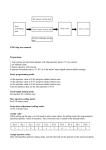
1.0 General Guide
Thank you for purchasing your new ADC.
We recommend reading this manual, and
practicing the operations before using your
ADC in the field.
The ADC is designed to provide you with
information essential to your needs. Data
such as temperature, wind speed, barometric
pressure, altitude and humidity are features
specific to four different ADC models: Wind,
Summit, Pro and JetSet.
Each ADC model is constructed to withstand
water submersion and is ideal for conditions
you endure during outdoor activities such as
hiking, climbing, hunting, kayaking, skiing,
and racing. Every ADC also includes current
time, daily alarm, chronograph and race
timer functions. ADCs are equipped with a
propeller and other precise sensors to
measure outdoor conditions.
WARNING !
! Make sure that you fully understand the
functions and limitations of the ADC
before relying on it.
! The ADC is an assisting device for the
outdoor user, and is not a substitute for
weather advisories from a weather
station. It is helpful to check the
readings provided by this product
periodically with those broadcasted by
the weather station.
2.0 Care and Maintenance
Prevent getting dirt in the ADC propeller. It
could clog the mechanism.
Avoid exposing this product to extreme heat
or extreme cold for an unreasonable amount
of time.
Avoid severe impacts to the ADC.
Store the ADC in a dry place when it is not in
use.
Clean the ADC with a soft moistened cloth
occasionally.
DO NOT expose the ADC to strong
chemicals such as gasoline and alcohol, as
they will damage this product.
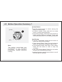
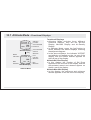
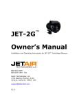
3.0 Part description
North Orientation
blade (RED)
1st row
2nd row
06MAR
THU
3rd row
12:38.28
4nd row
88.2% 28.0 8 C
Propeller
06MAR
THU
Display
Propeller
blades
12:38.28
88.2% 28.0 8 C
[mode]
Infrared Port
(send data from this
product to PC via
this port)
[light]
[set]
Detachable
Belt Clip
Buttons
[reset]
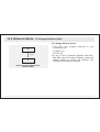
4.0 Button Operation Summary 1
[mode]
[set]
Note:
The button operations are
summarized in the following
paragraphs, for detail operating
instructions, please continue
reading.
[mode] Button
Press the mode button to select among the
major function modes
In function modes: Press and hold the mode
button to select setting display
In any setting display: Press the mode button to
select among different settings. Press and
hold the mode button to exit setting sequence.
[set] Button
In Current Time Mode: press the set button to
select the Daily Alarm Display.
In Daily Alarm Mode: Press the set button to
switch the daily alarm between ON and OFF.
In Chronograph Mode and Race Timer Mode:
Press the set button to start or stop the
counting.
In Lap Time Recall Mode: Press the set button
to select the available lap time(s).
In setting displays: press the set button to scroll
the through the settings.
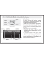
4.1 Button Operation Summary 2
[light]
[reset]
Note:
The button operations are
summarized in the following
paragraphs, for detail operating
instructions, please continue
reading.
[reset] Button
In Chronograph Mode (counting): Press the
reset button to get Lap Time Display.
In Chronograph Mode (stop-counting): Press
the reset button to reset the display to zero.
In Timer Mode (stop-counting): Press the
reset button to reset the timer to target time.
In Lap Time Recall Mode: Press the reset
button to select the available lap time(s).
In setting displays: press the reset button to
scroll the through the settings.
[light] Button
In any functional mode/display, press the light
button once to turn ON the EL backlight for
about 3 seconds.
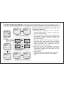
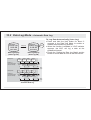
5.0 Major Functional Modes
BARO
hPa
[mode]
TEMP
1001.3
13.2
Temperature Mode
[mode]
mph
[mode]
Current Time Mode
[mode]
144
2:10.30
0:10.00
80
r001-0023
Altitude Mode
Data Log Mode
Daily Alarm Mode
[mode]
RACE TIMER
[mode]
12:00
88.2% 28.0 8 C
8.3
Wind Mode
DAILY ALARM
ON
12:38.28
21.3
18.3
[set]
06MAR
THU
DATALOG
06 MAR 2003
ALTITUDE m
734
WIND
28.3
18.2
Barometer Mode
8 C [mode]
[mode]
[mode]
0:00.00
00
Race Timer Mode
Chronograph Mode
Time Function
Sensor Function
Major Functional Modes
CHRONO
GRAPH
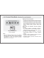
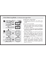
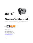
6.0 Current Time Mode - Functional Displays
Weather
Forecast
Symbol
Current
Time
06MAR
THU
12:38.28
Date
Day of week
88.2% 28.0 8 C
Current
Temperature
Weather Forecast Display
5 Seconds
ALTITUDE:
57m
12:38.28
88.2% 28.0 8 C
Mode
Indicator
Current
Altitude
Altitude Display
5 Seconds
5 Seconds
BAROMETER:
1001.3h Pa
12:38.28
88.2% 28.0 8 C
Barometer Display
Current Time Mode
Mode
Indicator
Current
Barometric
Pressure
Functional Displays
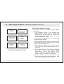
! Current Time Mode includes three different
displays: the Weather Forecast Display,
Altitude Display and Barometer Display.
! The above displays rotate through every 5
seconds.
! The current time, relative humidity and current
temperature appear on the 3rd and 4th row of
the display respectively.
Weather Forecast Display
! In Weather Forecast Display, the weather
forecast symbol and day of week appear on
the 1st and 2nd row of the display respectively.
C h e c k t h e c o m i n g ' We a t h e r F o r e c a s t
Symbols' section below for more detail on the
means of the weather forecast symbols
Altitude Display
! The indicator 'ALTITUDE' appears on the 1st row
of the display. The altitude at the current
location appears on the 2nd row of the display.
Barometer Display
! The indicator 'BAROMETER' appears on the 1st
row of the display. The current barometric
pressure appears on the 2nd row of the
display.
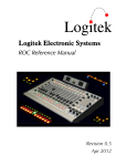
6.1 Current Time Mode - Setting the Current Time Mode
06MAR
THU
reset Second to zero
12:38.28
88.2% 28.0 8 C
Current Time Mode
hold
[mode]
'12' changes to '24';
'24' changes to '12'.
[set]
or [reset]
hold
[mode]
[set]
or [reset]
[mode]
12/24
second
[reset]
scroll through
the settings by
increment
hold [reset]
scroll
the setting at
a faster pace
[set]
scroll through
the settings by
decrement
hold [set]
scroll
the setting at
a faster pace
[mode]
hour
[mode]
minute
[mode]
[mode]
year
month
[mode]
[mode]
date
Current Time Setting Sequence
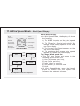
To Select Setting Display
! Setting the current time and date, and their
display formats, press and hold the [mode]
button for about 2 seconds to select the
setting display (the '12' indicator will start
flashing).
The Setting Sequence
! In setting display, press the [mode] button to
move the setting following the adjacent
diagram.
! When the ' 12 ' or ' 24 ' digits starts flash,
press the [set] or [reset] button to switch
between ' 12 ' (12 hour format) and ' 24 ' (24
hour format). When the ' second ' digits starts
flash on the display, press [set] or [reset]
button to reset the second to zero.
! If one of the settings (minute, hour, year,
month, date) starts flash, press the [set] or
[reset] button to scroll through the setting
(hold down the button to scroll the setting at
a faster pace).
! When the above settings finished, press and
hold the [mode] button for about 2 seconds
to exit the setting sequence.
6.2 Current Time Mode - Weather Forecast Symbols
Weather Forecast Symbols
Sunny
Partial Cloudy
Cloudy
Rainy
Stormy
06MAR
THU
12:38.28
88.2% 28.0 8 C
Weather Forecast Display
Current Time Mode
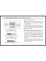
Note:
! When the ADC has been reset or the battery
has been replaced, partial cloudy symbol will
be displayed. To get an accurate weather
forecasting, the ADC must stay at the same
altitude for over 12 hours.
Weather Forecast Symbol
! The ADC includes a weather forecast function
that predicts the weather for the next 12 hours.
! The ADC will display the forecasted weather
by the weather forecast symbol. There are five
kind of weather forecast symbols, they are the
Sunny, Partial Cloudy, Cloudy, Rainy and
Stormy.
What Does the Weather Forecast Symbol
indicate
! A 'Sunny' symbol generally indicates
improving weather or sunny weather ahead.
! A 'Partial Cloudy' symbol generally indicates
slightly cloudy weather ahead.
! A 'Cloudy' symbol generally indicates
deteriorating weather or cloudy weather
ahead.
! A 'Rainy' symbol generally indicates adverse
weather or rainy weather ahead.
! A 'Stormy' symbol generally indicates stormy
weather ahead.
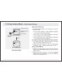
7.0 Daily Alarm Mode - Daily Alarm Display
Mode indicator
DAILY ALARM
ON
12:00
Alarm ON/OFF
Status
Alarm time
Alarm ON Alarm ON Display
Indicator
[set]
DAILY ALARM
OFF
-- : -Alarm OFF Display
Daily Alarm Mode
Daily Alarm Display
! In Daily Alarm Mode, the display will show
the following:
1) The mode indicator ' DAILY ALARM ' appears
on the 1st row of the display.
2) The ' ON ' or ' OFF ' status indicator appears
on the 2nd row of the display.
3) The alarm time (hour and minute) appears
on the 3rd row of the display.
To Select Daily Alarm between ON and OFF
! To select the daily alarm between ON and
OFF, press the [set] button once.
! When the daily alarm is ON, the Alarm ON
Indicator '
' appear otherwise it is OFF.
Daily Alarm Sound
! When the daily alarm is ON, the product will
beep at the predefined alarm time for about
30 seconds.
! When the beep sounds, it can be stopped
prematurely by pressing any of the buttons
except the [light] button.
7.1 Daily Alarm Mode - Setting the Daily Alarm Mode
DAILY ALARM
ON
scroll the
setting by
increment of 1
scroll
the setting
faster
12:00
hold
[reset]
[reset]
Daily Alarm Mode
hold
hold
[mode]
[mode]
[mode]
Minute
Hour
[mode]
Daily Alarm Mode
Setting Sequence
[set]
scroll the
setting by
decrement of 1
hold [set]
scroll
the setting
faster
To Select the Setting Display
! Setting the Daily Alarm Time, press and
hold the [mode] button for about 2 seconds
to select the setting display (the 'minute'
digits will start flashing).
The Setting Sequence
! In setting display, press the [mode] button to
move the setting between minute and hour
settings.
! When one of the settings (minute and hour)
digits start to flash on the display, press the [set]
or [reset] button to scroll through the setting
(hold down the button to scroll the setting at a
faster pace).
! When the setting finished, press and hold the
[mode] button to exit the setting sequence.
! The setting display will change to Current Time
Mode automatically if no key-stoke has been
activated for about 1 minute.
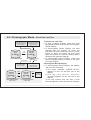
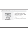
8.0 Chronograph Mode - Chronograph Display
Mode Indicator
CHRONO
GRAPH
Chronograph
Time (hour)
Chronograph
Time (second)
0:00.00
00
Chronograph
Time (minute)
Chronograph Time
(1/100 Second)
Chronograph Mode
(Zero Display)
0
30
[set]
[set]
1. Elapsed time
2. Accumulative
elapsed time
0
10
10
20
[set]
[set]
[set]
[set]
0
10
10
[set]
[reset]
[reset]
0
10
20
3. Lap time
time
30
40
Elapsed Time, Accumulative Elapsed Time and Lap Time
: Stop Counting
: Counting
Chronograph Function
! The ADC is equipped with a Chronograph
Mode, it can measure 3 different periods of
time. They are:
1) Elapsed time,
2) Accumulative elapsed time
3) Lap time
Chronograph Display
! In Chronograph Mode, the display will show
the following:
1) T h e m o d e i n d i c a t o r ' C H R O N O G R A P H '
appears on the 1st and 2nd row of the
display.
2) The chronograph time (hours, minutes,
seconds) appears on the 3rd row of the
display.
3) The lap number and chronograph time
(1/100 second) appears on 4th row of the
display.
! The display shows the 'Zero' display, if the
product or the chronograph has been reset.
! The maximum counting range of the
chronograph is 99 hours, 59 minutes and
59.99 seconds. The chronograph can record
up to 50 laps.
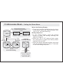
8.1 Chronograph Mode - Using the Chronograph
Lap Time
(the chronograph
is counting in the
background)
CHRONO
RUNNING
0:00.00
1L
Lap No.
01
Chronograph Mode
(Lap Time Display)
10 seconds
CHRONO
GRAPH
[reset]
CHRONO
RUNNING
[set]
0:00.00
0:00.00
00
counting
Chronograph Mode
('Zero' Display)
Chronograph Mode
(Counting Display)
Elapsed Time
(the chronograph
is stop counting)
[reset]
Note:
This diagram illustrates the
general flow among different
functional displays only, and
may NOT conform to fact in all
instances.
01
[set]
CHRONO
STOP
0:00.00
20
Chronograph Mode
(Stop Counting Display)
Chronograph Function
! In 'Zero' Display, press the [set] button once
to start the counting. When it is counting,
press the [set] button again to stop the
counting, and the elapsed time of which the
chronograph is counting will appear.
! When the elapsed time is displaying, repeat
the key operations above to get the
accumulative elapsed time or press the
[reset] button to reset the chronograph.
Check the below 'To Reset the Chronograph'
section for more detail on how to reset the
chronograph.
To Record a Lap Time
! When the chronograph is counting in the
previous operations, press the [reset] button
to display Lap Time Display for 10 seconds.
! When the Lap Time is displaying, the
chronograph remains counting in the
background.
To Reset the Chronograph
! To reset the chronograph, to be ready for a
new operation, press the [reset] button once
when the chronograph has stopped counting.
The display will then return to 'Zero' Display.
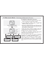
8.2 Chronograph Mode - Recall the Lap Time
Select the lap time by
backward scrolling
(fast scrolling)
Select the lap time by
backward scrolling
(1 lap per step)
hold [set]
CHRONO
STOP
[set]
CHRONO
RECALL
hold
[mode]
0:00.00
0:02.02
20
20
Stop Counting Display
Lap Time Recall Display
(Total Time)
[reset]
hold [reset]
Select the lap time by
forward scrolling
(fast scrolling)
CHRONO
RECALL
[reset]
1L
Lap No.
0:02.02
20
Select the lap time by
forward scrolling
(1 lap per step)
CHRONO
RECALL
[set]
0:04.02
2L
[reset]
[set]
20
Lap Time
Lap Time Recall Display
(Lap 1 Time)
Lap Time Recall Display
(Lap 2 Time)
Next
Available
Lap Time(s)
To Recall the Lap Time
! In Stop Counting Display, press and hold
the [mode] button to select the Chronograph
Recall Display.
! In Chronograph Recall Display, the total
elapsed time will appear. To recall the
individual lap time, press the [set] or [reset]
button to select the target lap time (hold
down the button to scroll the setting faster)
following the adjacent diagram.
! In Chronograph Recall Display, press and
hold the [mode] button to return to the Stop
Counting Display.
Chronograph Recall Display
! In Chronograph Recall Display, the display
will show the following:
1) The mode indicator ' CHRONO RECALL '
appears on the 1st and 2nd row of the
display.
2) T h e l a p t i m e ( h o u r s , m i n u t e s ,
seconds) appears on the 3rd row of the
display.
3) The lap number and lap time (1/100
second) appears on the 4th row of the display.
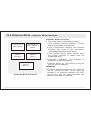
9.0 Race Timer Mode - Race Timer Display
Mode
Indicator
The Target Time
! The ADC is equipped with a countdown timer to
keep track of a fixed period of time (target time).
! The user can set a target time of up to 99 hours,
59 minutes 59 seconds.
! Check the coming 'Setting the Race Timer
Mode' section for more detail on how to set the
target time in Racer Timer Mode.
Race Timer Display
! In Race Timer Mode, the display will show the
following:
RACE TIMER
0:10.00
Target Time
(Hour, minute,
second)
Race Timer Mode
30
1. Single-phase
down
counting
2. Multi-phases
down
counting
3. Reset to
preset
target time
time
0
[set]
beep
30
20
20
[set]
[set]
[set]
30
20
30
[set]
[set]
[reset]
0
10
20
0
beep
30
Single/multi-down Counting & Reset
: Stop Counting
: Counting
40
1) The mode indicator ' RACE TIMER ' appears
on the 1st row of the display.
2) T h e t a r g e t t i m e ( h o u r s , m i n u t e s ,
seconds) appears on the 3rd row of the
display.
! The maximum counting range of the Race
Timer is 99 hours, 59 minutes and 59
seconds.
9.1 Race Timer Mode - Setting the Race Timer Mode
RACE TIMER
0:10.00
scroll
thesetting
settingat
the
fasterpace
a faster
scroll
the
scroll
through
by by
thesetting
settings
increment
of 1
increment
hold
[reset]
[reset]
Race Timer Mode
hold
[mode]
[mode]
hold
[mode]
Second
[mode]
Minute
[mode]
Hour
Race Timer Mode
Setting Sequence
[set]
scroll
the
scroll
through
by by
thesetting
settings
decrement
of 1
decrement
hold
[set]
scroll
thesetting
settingat
the
fasterpace
a faster
To Select the Setting Display
! Setting the target time in Race Timer Mode,
press and hold the [mode] button for about 2
seconds to select the setting display (the
second digits will start flashing).
Setting Sequence
! In setting display, press the [mode] button to
move setting following the adjacent diagram.
! When the one of the settings (second, minute,
hour) start to flash, press the [set] or [reset]
button to scroll through the settings (hold down
the button to scroll at a faster pace).
! When the setting finished, press and hold the
[mode] button for about 2 seconds to exit the
setting sequence.
! The setting display will change to Race Timer
Mode automatically if no key-stoke has been
activated for about 1 minute.
9.2 Race Timer Mode - Using the Race Timer
RACE TIMER
0:10.00
stop
counting
Stop-Counting Display
set the
target
time to
30 minute
RACE TIMER
STOPPED
beeps
0:00.00
Stop-Counting Display
29'59"
RACE TIMER
RACE TIMER
RUNNING
[set]
0:30.00
0:29.59
counting
Counting Display
Stop-Counting Display
[set]
[reset]
stop
counting
Note:
This diagram illustrates the
general flow among different
functional displays only, and
may NOT conform to fact in all
instances.
RACE TIMER
STOP
0:29.59
Stop-Counting Display
To Use the Race Timer
! Once a target time has been set, press the
[set] button once to start the countdown.
When it is running, press the [set] button
again to stop the countdown.
! The countdown time will be displayed
continuously throughout the operation.
To Reset the Timer
! To reset the timer to the preset target time
before the countdown reaches zero, press
the [reset] button once when the timer has
been stopped.
! To set a new value for the target time, check
the previous 'Setting the Race Timer Mode'
section for more detail on how to set the
Racer Timer Mode.
Race Timer Alarm Sound
! At the last 10 minutes, the Alarm will beep
once for every minute.
! At the last 10 seconds, the Alarm will beep
once for every second.
! At zero, the Alarm will beep for about 2
seconds.
10.0 Sensor Functions Mode - Manual Data Log Function
BARO
hPa
TEMP
WIND Km/H
1001.3
21.3
18.3
Barometer Mode
28.3
8.3
18.2
Wind Mode
144
80
Altitude Mode
Sensor Functional Mode
hold [set]
13.2
Temperature Mode
ALTITUDE m
734
8C
2 beeps
Record no. & Data no
Logging time & date
ambient
temperature
current
wind speed
altitude at the
current location
ambient barometric
pressure
Data (The Elements of a Data)
Data Log Function
! The ADC is equipped with a function to log
the sensor functional mode readings. They
are the current wind speed, ambient
temperature, barometric pressure and the
altitude at current location.
! The record also includes the time and date
that data was logged.
! The ADC can log data automatically or
manually. Check the 'Automatic Data Log'
section below for more detail on how to log
data automatically.
To Log the Data Manually - Manual-Log
! To log a data manually, press and hold the [set]
button for about 2 seconds in one of the
functional modes (Temperature, Wind Speed,
Barometer and Altimeter).
! When two beeps sounds, the record is logged.
! You can log another record at any desirable
moment as long as there is sufficient memory.
! Check the coming 'Logged Record and Data'
section for more detail on how to review the
logged data.
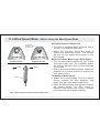
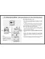
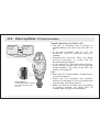
11.0 Wind Speed Mode - Before Using the Wind Speed Mode
the propeller
blades are entirely
exposed to air
Propeller Closed
wind
Propeller Opened
wind
display
Point the Propeller towards the wind direction
How Wind Speed is Measured
! The ADC is equipped with a propeller that is
similar to a traditional aerovane.
! When the propeller faces the wind, it
rotates and generates signal. This product
will pick up the signal and converts it into
wind speed.
Before and After Measuring a Wind Speed
! Turn the ball-shape propeller by your thumb
and index finger until the propeller blades
are entirely exposed, and it is not sheltered
by the case.
! After a wind speed measurement, rotate the
propeller to a closed position to prevent dirt
from getting into it.
To Measure Wind Speed
! Select Wind Speed Mode. Point the blades
directly towards the wind direction, and
make sure that the blades rotate freely.
! When the wind passes through the propeller,
the blades rotate. The ADC starts to
measure, and shows the current, average
and maximum wind-speed readings.
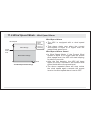
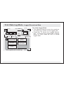
11.1 Wind Speed Mode - Wind Speed Mode Function
Beaufort
Scale
Current, Max
and Average
Wind Speed
Wind Speed
Display Lock
Wind
Speed
Alarm
Time Span
Setting
Manual
Data Log
Wind Speed Mode Functions
Wind Speed Mode Functions
! This ADC has the following wind speed
functions:
1) The Beaufort Scale: The longest and
most widely used set of criteria to
describe the wind conditions. Check the
coming ' Beaufort Scale ' section for more
detail on Beaufort Scale.
2) The Current, Maximum and Average
Average Wind Speed.
3) Wind Speed Alarm: alarm that alerts the
user when the current wind speed is higher
than the predefined level.
4) Wind Speed Display Lock: This feature
can lock the wind speed display for 5
seconds.
5) Time Span Setting: This feature defines
the time for the Average Wind Speed
Calculation. Check the coming ' Time
Span Setting for Average Wind Speed '
section for more detail on the setting.
6) Manual Data Log: The function to log
the sensor functional mode readings that
is currently obtained from sensors.
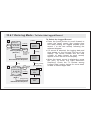
11.2 Wind Speed Mode - Wind Speed Display
Mode
Indicator
Wind
Speed Unit
WIND
Beaufort
Scale
(by average
wind speed)
Maximum
Wind Speed
mph
21.3
18.3
Current
Wind Speed
8.3
Average
Wind Speed
Wind Speed Mode
[reset]
mph
Km/h
[reset]
[reset]
m/s
[reset]
feet/s
[reset]
Knots
Wind Speed Unit Selection Sequence
Wind Speed Display
! In Wind Speed Mode, the display will show
the following:
1) The ' WIND ' Indicator and the wind speed
unit appear on the 1st row of the display.
2) T h e B e a u f o r t S c a l e ( c a l c u l a t e d b y
average wind speed) appears on the 2nd
row of the display.
3) The Current Wind Speed appears on the
3rd row of the display.
4) The maximum and average wind speed
appears on the 4th row of the display.
To Change Wind Speed Unit
! This ADC can display wind speed in the
following wind speed units:
1) Km/h (Kilometer per hour),
2) mph (mile per hour),
3) feet/s (feet per second)
4) m/s (meter per second) and
5) Knots.
! In Wind Speed Mode, press the [reset]
button to change the wind speed unit
following the adjacent diagram.
11.3 Wind Speed Mode - What is Beaufort Scale?
Beaufort
Scale
(by average
wind speed)
WIND
mph
21.3
18.3
Average
Wind Speed
8.3
Wind Speed Mode
Beaufort Scale
(calculated by average wind speed)
force
no. 1
force
no. 5
force
no. 10
Example A: Number 5 of Beaufort Scale
Beaufort Scale
(calculated by average wind speed)
force
no. 1
force
no. 8
force
no. 10
Example B: Number 8 of Beaufort Scale
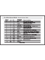
What is Beaufort Scale?
! Beaufort Scale is the longest and most
widely used set of criteria to describe the
wind conditions and its effects on land as
well as on sea.
! It categorizes the wind speed into 13 force
numbers, from 0 (calm) to 12 (hurricane).
Check the 'Beaufort Scale Table' section
below for more detail on the Beaufort Scale.
Beaufort Scale Bar
! For user's convenience, the ADC displays
Beaufort Scale for average wind speed.
! T h e A D C e x h i b i ts B e a u f o r t S c a l e b y
displaying different number of bars on the
upper row of the display. One exhibited bar
is equivalent to one Beaufort Scale force
number. For example, if there are 5 bars on
the display, the average wind speed is
equivalent to force number 5 of Beaufort
Scale.
! The ADC displays the Beaufort Scale force
number from 0 to 10 (if the average wind
speed is higher than force number 10, the
ADC will display 10).
11.4 Wind Speed Mode - Beaufort Scale Table
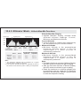
11.5 Wind Speed Mode - Wind Speed Display Lock, Reset Max Wind Speed
WIND mph
21.3
18.3
8.3
Wind Speed Mode
[set]
hold
[reset]
5 seconds
WIND mph
lock
indicator
L
18.3
RESET MAX
WIND? NO
21.3
8.3
Wind Speed Mode
(Display Locked)
18.3
display
keep still
Note:
This diagram illustrates
the general flow among
different functional
displays only, and may
NOT conform to fact in
all instances.
8.3
flashing
Maximum Wind Speed
Reset Display - NO
hold
[mode]
[set]
(confirm
the
reset)
RESET MAX
WIND? YES
18.3
8.3
flashing
Maximum Wind Speed
Reset Display - Yes
hold
[mode]
(abort the
reset)
Wind Speed Display Lock
! The ADC is equipped with a function to hold
the fluctuating wind speed reading on the
display.
! In Wind Speed Mode, press the [set] button
to lock the wind speed reading (the display
will hold the current reading for 5 seconds).
Reset the Maximum Wind Speed
! To reset the maximum wind speed, press
and hold the [reset] button for 2 second to
select the Reset Display.
! When the Reset Display is displayed, press
the [set] button to select between 'YES' and
'NO'.
! In the ' YES ' display, press and hold the [mode]
button for 2 about seconds to confirm the
reset (the maximum wind speed will reset to
zero).
! To abort the reset, press and hold the [mode]
button for 2 seconds in the ' NO ' display.
11.6 Wind Speed Mode - Wind Speed Alarm
Wind Speed
Alarm Range
'beep'
for 5
seconds
(every 2
minutes)
preset
wind speed
level
Below Alarm Range
Time
0
The Wind Speed Alarm Range
Wind Speed Alarm
! The ADC is equipped with a wind speed
alarm.
! That alarm alerts user when the current
wind speed is equal to or higher than the
preset wind speed level.
Wind Speed Alarm Sound
! In Wind Speed Mode, if the Current Wind
Speed is equal to or larger than the preset
wind speed level, the ADC will start beeping
for about 5 seconds.
! After the first beeping, the ADC will beep
again for every 2 minutes if the current wind
speed holds above the preset level.
! The above repeated alarm will stop unless
the wind speed again exceeds the preset
level or the wind speed alarm is set to OFF.
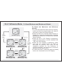
11.7 Wind Speed Mode - Setting the Wind Speed Alarm and Time Span
hold
[mode]
Wind Speed Alarm and
Time Span Setting Sequence
WIND mph
[mode]
18.3
8.3
Time Span
Setting
Wind Speed
Alarm
21.3
hold
[mode]
Wind Speed Mode
Time Span
Setting
Wind Speed Alarm Setting
Alarm OFF
Alarm ON
WIND mph
OFF
----
18.3
8.3
[set]
WIND mph
ON
flash
50.3
18.3
WIND mph
AVG PERIOD
10
SEC
8.3
hold [reset]
[reset]
hold [reset]
[reset]
scroll
thesetting
settingat
the
faster
a faster
pace
scroll through
the settings by
increment
scroll
the setting at
a faster pace
scroll through
the settings by
decrement
To Set the Wind Speed Alarm, and Time Span
for Average Wind Speed Calculation
! To set the wind speed alarm, press and hold
the [mode] button for about 2 seconds to
select the setting display (wind speed starts
flashing).
! When the 'wind speed' is flashing, press the
[mode] button to select between time span
setting and wind speed alarm setting.
! When 'wind speed' is flashing, press the
[reset] button to scroll the target wind speed
level by 1 step (hold down the button to
scroll the setting faster). To select the wind
speed alarm between ON and OFF, press
the [set] button.
! When 'time' is flashing, press the [set] or
[reset] button to scroll the target time span
for average wind speed calculation by 1
(hold down the button to scroll the setting
faster).
! Press and hold the [mode] button for about
2 seconds to exit the setting sequence.
! The setting display will change to Wind
Mode automatically if no key-stoke has
been activated for about 1 minute.
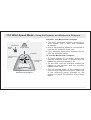
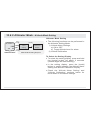
11.8 Wind Speed Mode - Using the Propeller as a Mechanical Compass
North East
North
pole
Target object
propeller
red-colored
blade
reference
points
Using the Propeller as a
Mechanical Compass
Propeller as a Mechanical Compass
! The ADC measures ambient temperature,
wind speed, and it also tells compass
directions.
! One of the propeller blades is red-colored to
indicate the magnetic north pole.
! Four reference points were engraved on the
ADC as reference points.
To use the Mechanical Compass
! To check bearing of an object, make sure
that the propeller cover is opened, and the
blades are entirely exposed to air.
! Tilt the ADC until the propeller blades are
parallel to the horizon, and the propeller
blades rotate freely.
! The red-colored blade of the propeller will
points to the magnetic north pole. Make use
of the reference points (marked on the
product) to check the direction of the target
object.
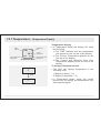
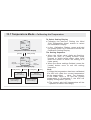
12.0 Temperature - Temperature Functions
Current
Temperature
Current, Minimum
Wind Chill
Temperature
Temperature
History Graph
Wind Chill
Temperature
Alarm
Temperature
Calibration
Manual
Data Log
Temperature Mode Functions
Temperature Mode Functions
! The ADC has the following temperature
functions:
1) The Current Temperature: The Current
Temperature readings.
2) The Current and Minimum Wind Chill
temperature: The wind effect on
temperature. Check the'WindChill
Temperature' section below for more detail
on Wind Chill Temperature.
3) The Temperature History Graph: The
temperature memory for the last 24 hours.
4)
The Wind Chill Temperature Alarm:
alarm to alert the user when the current
Wind Chill Temperature is lower than the
predefined limit.
5) The Calibration: The process to calibrate
the temperature reading.
6) Manual Data Log: The function to log the
sensor functional mode readings that is
currently obtained from sensors.
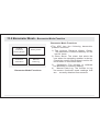
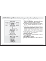
12.1 Temperature - Temperature Display
Mode
Indicator
TEMP
C
28.3
Current Wind Chill
Temperature
18.2
13.2
Temperature Mode
C
[reset]
F
Temperature
Unit
Current
Temperature
Minimum Wind Chill
Temperature
Temperature Display
! In Temperature Mode, the display will show
the following:
1) The ' TEMP ' Indicator and the temperature
unit appear on the 1st row of the display.
2) The Current Temperature appears on the
3rd row of the display.
3) The Current and Minimum Wind Chill
Temperature appear on the 4th row of the
display.
To Change Temperature Unit
! The ADC can display temperature in the
following units:
1) Degree Celsius ( 8 C)
2) Degree Fahrenheit ( 8 F)
! In Temperature Mode, press the [reset]
button once to change the temperature unit.
See adjacent figure.
12.2 Temperature Mode- Wind Chill Temperature
Wind
Case Conditions
1.
2.
3.
NO wind
wind speed
at 50 mph/
80.5 km/h
NO wind
Current
Wind Chill
Temperature Temperature Weather
15F/ -9.4C
15F/ -9.4C
Cold
15F/ -9.4C
-10F/ -23.3C
Very
Cold
-10F/ -23.3C
-10F/ -23.3C
Very
Cold
Wind Chill Temperature Effects
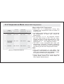
What is Wind Chill Temperature
! Wind chill is a temperature factor that
combines air temperature and the effect of
blowing wind.
! As blowing wind makes you feel as though
the temperature is lower than simple air
temperature.
! For example, if it is -9.4 degrees Celsius
and the wind blows at 80.5 km per hour:
People will feel as if the temperature is -23.3
degrees Celsius. In this case, the wind chill
temperature is
-23.3 degrees Celsius.
! The ADC is also equipped with wind chill
temperature functions, including displaying
current and minimum wind chill temperature,
and having a wind chill temperature alarm.
Note:
! Wind chill temperature is the effect that
combines wind speed and temperature, the
ADC must measure the wind speed in order
to display the wind chill temperature.
! Check the previous ' Before Using the Wind
Speed Mode ' section for more detail on
Wind Speed Measurement.
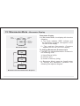
12.3 Temperature Mode - To Reset Minimum Wind Chill Temperature
TEMP
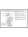
To R e s e t t h e M i n i m u m W i n d C h i l l
Temperature
! To reset the minimum wind chill temperature,
press and hold the [reset] button for 2
seconds to select the Reset Display.
! When the Reset Display is displaying, press
the [set] button to select between the ' YE S '
and ' NO ' Display.
8C
28.3
18.2
13.2
Temperature Mode
hold
[reset]
RESET MIN
W.CHILL? NO
18.2
hold
[mode]
(abort the
reset)
13.2
flashing
Maximum Wind Speed
Reset Display - NO
Note:
This diagram illustrates
the general flow among
different functional
displays only, and may
not conform to fact in
all instances.
hold
[mode]
(confirm
the
reset)
[set]
RESET MIN
W.CHILL? YES
18.2
13.2
flashing
Maximum Wind Speed
Reset Display - Yes
! In the ' YES ' display, press and hold the [mode]
button for about 2 seconds to confirm the
reset (the minimum wind chill temperature
will reset to zero).
! To abort the reset, press and hold the [mode]
button for 2 seconds in the ' NO ' display.
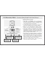
12.4 Temperature Mode - Temperature History Graph for the Last 24 Hours
TEMP
8C
28.3
18.2
13.2
Temperature Mode
[mode]
[set]
-24 hour
0 hour (current)
the temperature
of the selected
record (numeric)
TEM
8C
28.3
18.2
current
wind chill
1-00
flashing bar
represents
the selected record
(graphical bar)
the time that took
this record
Temperature History Graph Display
hold [reset]
[reset]
Select the record by
forward scrolling
(1 hour per step)
Select the lap time by
forward scrolling
(fast scrolling)
hold [set]
[set]
Select the record by
backward scrolling
(1 hour per step)
Select the lap time by
backward scrolling
(fast scrolling)
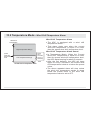
Temperature History Graph
! The ADC is equipped with a temperature
memory function. It records the last 24-hour
temperature and displays them by bar-graph.
! In Temperature Mode, press the [set] button
to select the Temperature History Graph
Display.
! While in the Temperature History Graph
Display setting, the right most bar will start
flashing.
! The right most bar represents the current
temperature (0 hour). While the other bars
represent the temperature records of the last
24 hours. Each temperature record is taken
at the hour (i.e. 12:00, 1:00, 2:00 ...)
! To browse the temperature record at
different times, press the [set] button to
select the record by backward scrolling or
[reset] button to select time by forward
scrolling (hold down the button to scroll the
setting at a faster pace).
! Press the [mode] button once to exit the
Pressure History Graph Display.
12.5 Temperature Mode - Wind Chill Temperature Alarm
Wind Chill
Temperature
High Temperature Range
preset
wind chill
temperature
level
Low Temperature Range
'beep'
for 5
seconds
(every 2
minutes)
Time
0
The Wind Chill Temperature Alarm
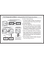
Wind Chill Temperature Alarm
! The ADC is equipped with a wind chill
temperature alarm.
! That alarm alerts user when the current
wind chill temperature is equal to or lower
than the preset wind chill temperature level.
Wind Chill Temperature Alarm Sound
! In Temperature Mode: When the Current
Wind Chill Temperature is equal to or lower
than the preset wind chill temperature level,
the ADC starts beeping for about 5 seconds.
! After the first beeping, the ADC will beep
again for every 2 minutes if the current wind
chill temperature holds at or below the preset
value.
! The above repeated alarm will stop unless
the wind chill temperature equals or drops
below the preset value or the wind chill
temperature alarm is set to OFF.
12.6 Temperature Mode - Setting the Wind Chill Temperature Alarm
Wind Chill Temperature Alarm and
hold Temperature Calibration
[mode] Setting Sequence
TEMP
8C
[mode]
Wind Chill
Temperature
Alarm
28.3
18.2
13.2
Temperature
Calibration
hold
[mode]
Temperature Mode
Temperature
Calibration Display
Wind Chill Temperature
Alarm Setting
Alarm ON
Alarm OFF
W.CHILL 8 C
OFF
----
18.3
8.3
[set]
TEMP
8C
OFFSET
W.CHILL 8 C
ON
0.0
-10.0
18.3
18.3
8.3
8.3
flash
hold
[reset]
scroll
the setting
faster
[reset]
scroll the
setting by
increment
of 1 step
[mode]
hold
[reset]
Calibration Setting Display
Check 'Calibrating
the Temperature' section
below for more detail
To Select Setting Display
! To select the setting display, press and hold
the [mode] button for about 2 seconds to
select the setting display (temperature digits
will start flashing).
The Setting Sequence
! When the temperature digits are flashing,
press the [mode] button to select between
the Wind Chill Temperature Alarm Setting
a n d Te m p e r a t u r e C a l i b r a t i o n D i s p l a y
following the adjacent diagram. Check the
'Calibrating the Temperature' section below
for more detail on temperature calibration.
! When the temperature digits are flashing,
press the [reset] button to scroll through to
select target wind chill temperature level
(hold down the button to scroll the setting at
a faster pace), or press the [set] button to
select the between wind chill temperature
alarm ON and OFF.
! When the above settings finished, press and
hold the [mode] button for about 2 seconds
to exit the setting sequence.
12.7 Temperature Mode - Calibrating the Temperature
TEMP
8C
OFFSET
0.0
18.3
8.3
Temperature Calibration Display
[mode]
hold [reset]
TEMP
8C
OFFSET
wind chill
temperature
0.0
18.3
8.3
the offset
value
current
temperature
Calibration Setting Display
hold [reset]
[reset]
Select the
setting by
forward scrolling
Select the setting by
forward scrolling
(fast scrolling)
hold [set]
[set]
Select the
setting by
backward scrolling
Select the setting by
backward scrolling
(fast scrolling)
To Select Setting Display
! Following the previous ' Setting the Wind
Chill Temperature Alarm ' section to select
the Calibration Display.
! In the Calibration Display, press and hold
the [reset] button for 2 seconds to select the
Calibration Setting Display.
The Setting Sequence
! When the 'offset value' digits are flashing,
press the [set] or [reset] buttons scroll
through to select target offset value (hold
down the button to scroll the setting at a
faster pace).
! When the above settings finished, press the
[mode] button once to exit the setting
sequence.
Note:
1) When the temperature has been calibrated,
the ADC will offset the current temperature
by the target offset
value. For example:
If the offset value is +2 and the current
temperature is 26 degrees C, the ADC will
display 28 degrees C (26+2).
2) The current wind chill temperature will be
updated as above accordingly.
13.0 Barometer Mode - Barometer Mode Function
24 Hour
Pressure
History Graph
Stormy Alarm
Pressure
Calibration
Manual
Data Log
Barometer Mode Functions
Barometer Mode Functions
! The ADC has the following barometric
pressure functions:
1) The 24-Hour Pressure History Graph:
The Barometric Pressure Memory for the
last 24 hours.
2) Storm Alarm: The alarm that alerts the
user when the upcoming weather is stormy.
Check the coming 'Storm Alarm' section for
more detail on the Storm Alarm.
3)
Calibration: The process to calibrate
the Barometric Pressure reading.
4)
Manual Data Log: The function to log
the sensor functional mode readings that
are currently obtained from sensors.
13.1 Barometer Mode - Barometer Display
Mode
Indicator
BARO
hPa
1001.3
Pressure
Unit
Current
Barometric
Pressure
Barometer Mode
hPa
[reset]
mb
[reset]
[reset]
inHg
Barometric Pressure Unit Selection Sequence
Barometer Display
! In Barometer Mode, the display will show the
following:
1) The mode indicator ' BARO ' Indicator and
the barometric pressure unit appear on the
1st row of the display.
2) The ambient Barometric Pressure
appears on the 3rd row of the display.
To Change Barometric Pressure Unit
! The ADC can display Barometric Pressure in
the following units:
1) Hecto-Pascal (hPa)
2) milli-bar (mb)
3) Inches of mercury (inHg)
! In Barometer Mode, press the [reset] button
to change the barometric pressure unit
following the adjacent diagram.
13.2 Barometer Mode - Pressure History Graph for the Last 24 Hours
BARO
hPa
1001.3
Barometer Mode
[mode]
[set]
flashing bar
represents
the selected record
(graphical bar)
-24 hour
the pressure
of the selected
record (numeric)
BAR
hPa
1023.2
0 hour (current)
1-00
the time that
took this record
Pressure History Graph Display
hold [reset]
[reset]
Select the record by
forward scrolling from
-24 hour to current
(1 hour per step)
Select the lap time by
forward scrolling
(fast scrolling)
hold [set]
[set]
Select the record by
backward scrolling
from current to -24 hour
(1 hour per step)
Select the lap time by
backward scrolling
(fast scrolling)
Pressure History Graph
! The ADC is equipped with a barometric
pressure memory function. It records the last
24 hours barometric pressure readings, and
it can display them by bar-graph.
! In Barometer Mode, press the [set] button to
select the Pressure History Graph Display.
! While in the Temperature History Graph
Display, the right most bar will start flashing.
! The right most bar represents the current
temperature (0 hour), while the other bars
represent the pressure records of the last 24
hours. Each pressure record is taken at the
hour (i.e 12:00, 1:00 and 2:00 ... ).
! To browse the pressure record at different
times, press the [set] button to scroll the
record backward (from the current record to
the -24 hour record) or press the [reset]
button to scroll the record forward (from the
-24 hour record to the current record).
! Press the [mode] button once to exit the
Pressure History Graph Display.
13.3 Barometer Mode - About Storm Alarm
Weather Forecast Symbols
Stormy
beep
Storm
alarm on
06MAR
THU
12:38.28
88.2% 28.0 8 C
Weather Forecast Display
About Stormy Alarm
! The alarm gives beep alert when the ADC
predicts the upcoming weather as stormy.
! Then, in the Current time - Weather
Forecast Display, the 'stormy' weather
forecast symbol will appear.
Storm Alarm Sound
! If the 'stormy' weather forecast symbol
appears, the ADC starts beeping for about 30
seconds.
! The ADC will NOT beep again unless another
'stormy' condition is predicted.
13.4 Barometer Mode - Setting the Storm Alarm
hold
[mode]
BARO
Storm Alarm and Pressure
Calibration Setting Sequence
hPa
[mode]
Stormy
Alarm
1001.3
Pressure
Calibration
Barometer Mode
hold
[mode]
(Alarm OFF)
hold
[mode]
(Alarm ON)
BARO hPa
STORM OFF
1001.3
[set]
BARO hPa
STORM ON
Pressure
Calibration Display
BARO hPa
OFFSET
0.0
1001.3
1001.3
Alarm OFF
current
barometric Alarm ON
pressure
Storm Alarm Setting
[mode]
hold
[reset]
Calibration Setting Display
Check the 'Calibrating
the Temperature' section
below for more detail
Select the Setting Display
! Press and hold the [mode] button for about
2 second to select the setting display (the
' ON ' or ' OFF ' will start flashing).
Setting Sequence
! In the setting display, press the [mode]
button to move the setting following the
adjacent diagram.
! When the ' ON ' or ' OFF ' starts to flash, press
the [set] button to select the Stormy Alarm
between ON and OFF.
! When the above settings finished, press and
hold the [mode] button for about 2 seconds
to exit the setting sequence.
13.5 Barometer Mode - Calibrating the Barometric Pressure
BARO hPa
OFFSET
0.0
1001.3
Pressure Calibration Display
[mode]
hold [reset]
BARO hPa
OFFSET
0.0
1001.3
the offset
value
the current
value
Calibration Setting Display
hold [reset]
[reset]
Select the
setting by
forward scrolling
Select the setting by
forward scrolling
(fast scrolling)
hold [set]
[set]
Select the
setting by
backward scrolling
Select the setting by
backward scrolling
(fast scrolling)
To Calibrate the Barometric Pressure
! Following the previous 'Setting the Storm Alarm'
section to select the Calibration Display.
! In the Calibration Display, press and hold the
[reset] button for 2 seconds to select the
Calibration Setting Display.
! When the 'offset value' digits are flashing, press
the [set] or [reset] button to scroll to select the
target offset value (hold down the button to scroll
the setting at a faster pace).
! When the above settings finished, press the
[mode] button once to exit the setting sequence.
Setting Pressure relative to Sea Level
1) When the barometric pressure has been
calibrated, the current barometric pressure w i l l
offset by the target offset value.
2) To be able to read the current barometric
pressure as a pressure referring to sea-level
although at an altitude, calibrate as follows:
Check the current altitude (for example 1000m).
Divide 1000/8 (since 1 hPa/mbar is 8m altitude).
Result 125 hPa/mbar. Set offset to +125hPa/mbar.
The reading will now refer to the pressure at sealevel.
14.0 Altimeter Mode - Altimeter Mode Functions
Current, Min &
Max Altitude
Accumulative
Ascend & Descend
Altitude
Altitude
Calibration
Altitude
Alarm
manual
Data Log
Altimeter Mode Functions
Altimeter Mode Functions
! This mode has the following functions:
1) The different altitude readings: Current,
Minimum and Maximum Altitude.
2) The Accumulative Ascend and Descent
Altitude: The sums of the ascending/
descending distance for ski sport.
3) The Altitude Alarm: Alarm sounds when
the current altitude is higher than the
predefined level.
4) Altitude Calibration: The process to
calibrate the altitude reading.
5) Manual Data Log: The function to log the
current sensor readings.
WARNING !
! The ADC estimates altitude by air pressure.
Hence, these altitude values may be
changed if air pressure changes. DO NOT
rely on the ADC for those activities that
demands commercial standard.
14.1 Altitude Mode - Functional Displays
ALTITUDE m
SKI RUN: 99
144
2237
2418
Ski-Run Display
[set]
Mode
Indicator
ALTITUDE m
144
Max
Altitude
734
80
Max-Min Display
Altimeter Mode
Ski Run
number
Accumulated
Descent
Accumulated
Ascent
Altitude
unit
Current
Altitude
Min
Altitude
Functional Displays
! Altimeter Mode includes three different
functional displays, they are the Ski-Run
Display, Max-Min Display and Air-Density
Display.
! In Altimeter Mode, press the [set] button to
select between the above displays following
the adjacent diagram.
! In the above displays, the indicator 'ALTITUDE'
and altitude unit appear on the 1st row of the
display, and the current altitude appears on
the 3rd row of the display.
Altitude Ski-Run Display
! In this display, the number of Ski Runs
appears on the 2nd row of the display, and the
accumulated ascent and descent appear on
the 4th row of the display.
Altitude Max-Min Display
! In this display, the maximum and minimum
altitude appears on the 4th row of the display.
14.2 Altimeter Mode - To Change Altitude Units
m
[reset]
ft
Select among the Altitude Units
Altimeter Mode
To Change Altitude Units
! The ADC can display altitude in the
following units:
1) Meter (m)
2) Feet (ft).
! In any of the functional displays (Ski-Run,
Max-Min and Air-Density Display), press the
[reset] button to select the altitude unit
following the adjacent diagram.
14.3.0 Altimeter Mode - Altitude Ski-Run Display
Mode
Indicator
ALTITUDE m
SKI RUN: 99
Current
Altitude
Ski Run
counter
144
2237
Accumulated
Ascent
Altitude
unit
2418
Accumulated
Descent
Ski Run Display
Altimeter Mode
altitude (m)
A
record
ski-run count
(counter +1)
record
ski-run count
(counter +1)
500
D
B
E
>30 m
485
470
455
F
C
440
425
410
time
End
point
Starting
point
Ski-Run 1
Starting
point
Ski-Run 2
End
point
Ski-Run Display
! The ADC is equipped with functions to register
ski runs. They are the Ski-Run Counter,
Accumulative Ascending Altitude and
Accumulative Descending Altitude.
! The Ski Run Counter registers the number of
ski runs.
! The Accumulative Ascending Altitude and
Accumulative Descending Altitude registers
the total ascend or descend altitude during the
ski runs.
! When the Ski-Run functions is ON:
1)The ADC will record a Ski-Run count
(Counter +1) automatically when a ski run
has descended 15 meters (point A to B or
point D to E).
3) The ADC will record a new ski-run record
(Counter +1) once a 30 meters ascend
(point C to D) is completed before another
ski-run record is allowed to be registered.
! Check the 'To Turn the Ski-Run Function ON
and OFF' section below for more detail on how
to set the function ON and OFF.
14.3.1 Altimeter Mode - To Turn Ski-Run Function ON and OFF
Ski-Run Function ON-OFF Setting
Function OFF
Function ON
SKI RUN ON?
NO
[set]
hold [mode]
(Ski-Run
Function ON)
hold [mode]
(Ski-Run
Function OFF)
ALTITUDE m
SKI RUN: 99
hold
[reset]
144
2237
SKI RUN ON?
YES
Ski-Run
Function
ON-OFF
[mode]
Ski-Run
Counter
Reset
2418
[mode]
Ski Run Display
hold
[mode]
Ski-Run
Descend
Reset
[mode]
[mode]
Ski-Run
Ascend
Reset
Ski-Run Counter, Ascend and
Descend Reset Setting Sequence
To Turn Ski-Run Function ON and OFF
! To select the setting display, press and hold
the [reset] button for about 2 seconds (the
'YES' or 'NO' will start flashing).
! In setting display, press the [mode] button to
select between the Ski-Run Function ONOFF Setting and the Ski-Run Reset Settings
following the adjacent diagram. Check the
'To Reset the Ski-Run Counter, Ascend &
Descend' section below for more detail on
reset setting.
! When the Ski-Run Function ON-OFF Setting
'YES' or 'NO' is flashing, press the [set]
button to select between the Ski-Run
Function ON and OFF.
! When the 'YES' Display is flashing, press
and hold the [mode] button for about 2
seconds to confirm the setting and exit the
setting sequence (Ski-Run Function will turn
ON).
! When the 'NO' Display is flashing, press
and hold the [mode] button for about 2
seconds to abort the setting and exit the
setting sequence.
14.3.2 Altimeter Mode - To Reset the Ski-Run Counter, Ascend & Descend
SKIRUN
RESET? YES
[set]
SKIRUN
RESET? NO
ALTITUDE m
SKI RUN: 99
144
2237
2418
Activated
Inactivated
Ski-Run Counter Reset Setting
Ski Run Display
hold
[mode]
hold [reset]
Ski-Run
Function
ON-OFF
[mode]
Ski-Run
Counter
Reset
[mode]
DESCEND
RESET? YES
2237
2418
Activated
[set]
DESCEND
RESET? NO
Ski-Run
Descend
Reset
[mode]
Ski-Run
Ascend
Reset
Ski-Run Counter, Ascend
and Descend Reset
Setting Sequence
ASCEND
RESET? YES
2237
2237
[mode]
2418
[set]
ASCEND
RESET? NO
2237
2418
2418
Inactivated
Activated
Inactivated
Accumulative Descend Reset Setting
To Reset Ski-Run Counter, Ascending and
Descending Altitude.
! Following the previous 'To Turn Ski-Run
Function ON and OFF' section to enter the
Ski-Run Reset Setting.
! Press the [mode] button to select between
the Ski-Run Function ON-OFF Setting and
the Ski-Run Reset Settings following the
adjacent diagram.
! When one of the 'YES' Displays is flashing,
press and hold the [mode] button for about
2 seconds to confirm the reset and exit the
setting sequence (the respective Ski-Run
reading will be reset to zero).
! When one of the 'NO' Displays is flashing,
press and hold the [mode] button for about
2 seconds to abort the reset and exit the
setting sequence.
! IMPORTANT
Accumulative ascend and descend will only
work when Ski-Run function is activated
(ON)
14.4.0 Altimeter Mode - Altitude Max-Min Functions
altitude (m)
Highest point
Highest point
500
400
300
A
200
B
time
Starting
point
(reset the max
& min altitude)
Lowest
point
End
point
Starting
point
Trail 1
Lowest
point
End
point
Trail 2
This Product will display
at point A
at point B
Trail 1
Trail 2
Maximum 500 m
Altitude
Minimum 150 m
Altitude
550 m
500 m
550 m*1
200 m
150 m
150 m*2
Note:
1. The maximum altitude will be updated as a higher
altitude (550m > 500m) is reached.
2. The minimum altitude will NOT be updated as there is
NO further lower altitude (150m < 200m) accomplished.
Altitude Max-Min Display
! Altitude Max-Min Display includes three
different altitude readings: Current,
Minimum and Maximum Altitude.
Current Altitude
! Current Altitude is reading that measured by
the air pressure at your current location.
Minimum Altitude
! Minimum Altitude is the accomplished
minimum altitude record. It will be
superseded if a lower altitude is
subsequently achieved.
Maximum Altitude
! Maximum Altitude is the accomplished
maximum altitude record. It will be
superseded if a higher altitude is
subsequently achieved.
Note:
! During the first three minutes of Altitude Display,
the ADC needs one second to get a reading.
! After the first three minutes of Altitude Display,
the ADC needs one minute to get a reading.
! Reset the maximum or minimum altitude prior
to recording a new one, check the 'To Reset the
Maximum and Minimum Altitude' section below
to reset the respective reading.
14.4.1 Altimeter Mode - To Reset Minimum and Maximum Altitude
To Reset the Maximum and Minimum
Altitude
! To reset the maximum and minimum altitude,
press and hold the [reset] button for about 2
seconds to select the Reset Display.
! When the Minimum Altitude Reset Display is
displaying, press the [mode] button to select
between the Maximum and Minimum Altitude
Reset Display.
ALTITUDE m
144
734
hold
[mode]
(abort
the
reset)
80
Max-Min Display
hold [reset]
flashing
RESET MAX
ALT ?
NO
734
80
RESET MIN
ALT ?
NO
[mode]
flashing
Maximum Altitude
Reset Display - NO
734
Minimum Altitude
Reset Display - NO
[set]
RESET MAX
ALT ? YES
734
80
80
[set]
flashing
[mode]
flashing
Maximum Altitude
Reset Display - YES
RESET MIN
ALT ? YES
734
80
Minimum Altitude
Reset Display - YES
hold
[mode]
(confirm
the
reset)
! When the ' NO ' or ' YES ' Display is displaying,
press the [set] button to select between the
'YES' and 'NO' Display.
! When the ' YES ' Display is displaying, press
and hold the [mode] button for about 2
seconds to confirm the reset of the
respective altitude (i.e. the maximum or
minimum altitude), the maximum or minimum
altitude will be reset to zero.
! To abort the reset, press and hold the [mode]
button for 2 seconds in the ' NO ' Display.
14.5 Altimeter Mode - Altitude Alarm
Altitude
Undesirable Range
preset
altitude
level
'beep'
for 5
seconds
(every 2
minutes)
Desirable Range
Time
0
The Altitude Alarm
Altitude Alarm
! The ADC is equipped with an altitude alarm.
! That alarm alerts user when the current
altitude is equal to or higher than the preset
altitude level.
! Check the 'Setting the Altimeter Mode'
section below for more detail on how to set
the altitude level for the alarm.
Altitude Alarm Sound
! In Altitude Mode: When the current altitude is
equal to or higher than the preset altitude
level, the ADC starts beeping for about 5
seconds.
! After the first beeping, the ADC will beep
again for every 2 minutes if the current is still
equal or higher than the preset value.
! The repeated alarm beeps will stop until the
altitude is equal or higher than the preset
value or the Altitude Alarm is set to OFF.
14.6.0 Altimeter Mode - Altitude Mode Setting
ALTITUDE m
hold
[mode]
Altitude
Alarm
Setting
144
734
80
Altitmeter Mode
[mode]
Altitude
Calibration
Display
hold
[mode]
Altimeter Mode Setting
! The following functions can be performed in
the Altimeter Setting Mode.
1) Altitude Alarm Settings,
a) ON or OFF
b) Target Altitude Level for alarm
2) Altitude Calibration
Altimeter Mode Setting Sequence
To Select the Setting Display
! To select the setting display, press and hold
the [mode] button for about 2 seconds
(altitude digits will start flashing).
! In the setting display, press the [mode]
button to select between the Altitude Alarm
Setting and Altitude Calibration Display.
! Check the 'Altitude Alarm Setting' and
'Altitude Calibration' sections below for
more detail on the above settings.
14.6.1 Altimeter Mode - Setting the Altitude Alarm
Altitude Alarm Setting
Alarm ON
Alarm OFF
ALTITUDE 8
mC
W.CHILL
OFF
[set]
----
18.3
ALTITUDE m
ON
1800
144
8.3
hold
[reset]
scroll
the setting
faster
144
[reset]
scroll the
setting by
increment
of 1 step
flash
To Set the Altitude Alarm
! Following the previous 'Altimeter Mode
Setting Sequence' to select the Altitude
Alarm Setting Display.
! When the altitude alarm digits are flashing,
press the [reset] button to scroll by 1 to
select target altitude level (hold down the
button to scroll the setting faster), or press
the [set] button to select the between
altitude alarm ON and OFF.
! When the above settings finished, press and
hold the [mode] button for about 2 seconds
to exit the setting sequence or press the
[mode] button to set the other settings.
14.6.2 Altimeter Mode - Calibrating the Altitude
ALTITUDE m
ADJUST
0
144
the offset
value
the current
value
Altitude Calibration Display
[mode]
hold [reset]
ALTITUDE m
ADJUST
0
144
flashing
Calibration Setting Display
hold [reset]
[reset]
Select the
setting by
forward scrolling
Select the setting by
forward scrolling
(fast scrolling)
hold [set]
[set]
Select the
setting by
backward scrolling
Select the setting by
backward scrolling
(fast scrolling)
To Calibrate the Altitude
! Following the previous 'Altimeter Mode
Setting Sequence' enter the Calibration
Display. When the Calibration Display
appears, press and hold the [reset] button
for about 2 seconds to select the Calibration
Setting Display.
! When the 'offset value' digits are flashing,
press the [set] or [reset] button to scroll by 1
to select the target offset value (hold down
the button to scroll the setting faster).
! When the above settings finished, press the
[mode] button once to exit the calibration
setting sequence. To return to Altimeter
Mode, press and hold the [mode] button for
about 2 seconds to exit the setting
sequence or press the [mode] button to set
the other settings.
! Note:
1) When the altitude has been calibrated, the
ADC will offset the current altitude by the
target offset value. For example: If the offset
value is +20 and the current altitude is 144
the ADC will display 164 (144+20).
2) The maximum and minimum altitude will
NOT be updated as the above.
15.0 Data Log Mode - Data Log Function
A
B
data
data
record
data
Free Memory Display
Data Log Display
Record
C
Record no. & Data no
Logging time & date
ambient
temperature
current
wind speed
altitude at the
current location
ambient barometric
pressure
relative
humidity
The Elements of a Data
Record and Data
MEMORY
FULL
Memory Full Display
Data Log Function
! The ADC is equipped with a function to log
the sensor functional mode data. These
data are the current wind speed, ambient
temperature, barometric pressure, relative
humidity and the altitude at the current
location.
! This data also includes the time and date
that the logging was taken.
! The ADC can log data automatically (log a
data at a preset interval) or manually.
! For logging data automatically, check the
'Automatic Data Log' section below. For
logging data manually, check the previous
'Manual Data Log'.
Note:
1) The log memory can log up to 256 records
and 1980 data.
2) If log memory is full, a 'MEMORY FULL'
message will display for few seconds. Delete
some data, or transfer the data to PC if
necessary.
3) Always check the memory level before data
logging.
15.1 Data Log Mode - Data Log Display and Free Memory Display
the date that
this record
was logged
the record
no. of this
record
DATALOG
06 MAR 2003
the time that
this record
was logged
2:10.30
no. of data
logged by
this record
r001-0023
Data Log Display
3 seconds
FREE: 1350
06 MAR 2003
the free
memory
2:10.30
r001-0023
Free Memory Display
DATALOG
NO RECORD
-- : -- -r000-0000
Data Log Display
(NO Record)
Data Log Mode
NO data
is found
Functional Displays
! Data Log Mode includes two different
functional displays; they are the Free
Memory Display and Data Log Display.
! Free Memory Display and Data Log Display
will be appeared alternatively for every 3
seconds.
! In the above displays, the date of which the
record was logged appears on the 2nd row
of the display. The time of which the record
was logged appears on the 3rd row of the
display. The data number and record
number appear on the 4th row of the display.
! If NO data is found on the Data Log Mode,
the ' NO RECORD ' display appears.
The Data Log Display
! The mode indicator 'DATALOG' appears on the 1st
row of the display.
The Free Memory Display
! The free memory appears on the 1st row of the
display.
!
15.2 Data Log Mode - Automatic Data Log
DATALOG
06 MAR 2003
hold [set]
DATALOG
06 MAR 2003
2:10.30
2:10.30
r001-0023
r001-0023
Data Log Display
(Auto-Log OFF)
Data Log Display
(Auto-Log ON)
Example 1:
Record 1
(set 10 seconds
as the interval)
Example 2:
Record 2
(set 30 seconds
as the interval)
LOG
LOG
data 1
logged
data 2
logged
data 3
logged
data 4
logged
beep
beep
20
30
data 2
logged
data 3
logged
data 4
logged
hold [set]
to start beep
beep
beep
60
90
hold [set]
to start beep
0
10
data 1
logged
0
30
Automatic Data Log
hold [set]
to stop
40
time
(sec)
hold [set]
to stop
120
time
(sec)
To Log Data Automatically (Auto-Log)
! Press and hold the [set] button for about 2
seconds in the Data Log Mode to enable or
disable the automatic log function.
! When the function is enabled, a 'LOG' indicator
appears, the ADC will log a data at the
predefined interval.
! Check the 'Setting the Data Log Mode' section
below for more detail on how to set the interval..
15.3 Data Log Mode - Data and Record Administration
data 1
data 1
new
data
data 2
Log a
new data
data 2
data 3
Record
Record
Acquire a New Data
Record 1
Record 1
Record 2
Record 2
Record 3
Delete a
record
Delete a Record
Record 2
Log a New Data
! When a new data is logged, this data will
become the last one of the data list.
Delete a Existing Record
! If the displaying record is erased, the record will
shift it's location onward following the adjacent
diagram.
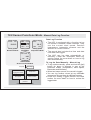
15.4.0 Data Log Mode - Data Log Mode Setting
Delete
the current
data
Logging
interval
setting
Delete
all Record
& Data
PC
Synchronization
Data Log Mode Setting
Data Log Mode Setting
! The following functions can be performed in
the Data Log Mode Setting.
1) Delete the current data
2) Set the logging interval for auto log
3) Enable the PC Synchronization
(transfer data from the ADC to PC)
4) Delete all data
! Check the 'PC Synchronization' section
below for more detail on the communication
between the ADC and PC.
15.4.1 Data Log Mode - Setting Data Log Mode
DEL? YES
06 MAR 2003
DATALOG
06 MAR 2003
2:10.30
r001-0023
flash
[set]
DEL? NO
06 MAR 2003
2:10.30
2:10.30
r001-0023
r001-0023
this data to
Activated
be deleted Inactivated
Delete the Current Data
Data Log Display
hold
[mode]
hold [mode]
DEL ALL ?
YES
Activated
1.
2.
Auto-Log
Delete the [mode]
Interval
record that
Setting
is displaying
[mode]
4.
Delete
all record
and data
[mode]
3.
PC Syn[mode] chronization
Data Log Mode
Setting Sequence
[set]
DEL ALL ?
NO
Inactivated
PC SYNC
START?
[set]
PC SYNC ...
STOP?
if the send
Ready
Sending
completed
PC Synchronization
To Select Setting Display
! Press and hold the [mode] button for about
2 seconds to select the Data Log Mode
Setting Display (the ' NO ' starts flashing).
! In setting display, press the [mode] button to
select among the settings following the
adjacent diagram.
1: When the ' NO ' starts to flash, press the
[set] button to select between ' YES '
(delete the record that is displaying) and
' NO ' Display.
2: When the interval digits starts to flash,
press the [set] or [reset] button to scroll to
select the target auto-log interval (hold
down the button to scroll the setting at a
faster pace).
3: When the 'PC SYNC START?' starts to
flash, press [set] button to send the data
from the ADC to PC.
4: When the ' NO ' starts to flash, press the
[set] button to select between ' YES ' (delete
all records) and ' NO ' Display.
! When the above setting completed, press
and hold the [mode] button for about 2
seconds to confirm the setting and exit the
setting sequence.
15.5
PC SYNC
START?
Ready
Data Log Mode - PC Synchronization
[set]
PC SYNC ...
STOP?
if the send
Sending
completed
PC Synchronization
PC SYNC
START?
Infrared Port
Pointing this port towards
the ADC-IR connected
to a PC
Transfer Data from the ADC to PC
! The ADC is equipped with a function to
transfer/backup the data from the ADC to
PC.
! To be able to transfer data to a PC, the
accessory ADC-IR (optional extra) is
needed.
! Following the previous 'Data Log Mode
Setting Sequence' to select the PC
Synchronization Display.
! In the above PC Synchronization Display,
press the [set] button once to activate the
synchronization. The data of the ADC will
send to the target PC.
Note:
! Start the PC's communication software prior
to the transmission.
! Check the PC's hardware and software
manual for the detail on how to transfer and
receive data via infrared device.
! Make sure that the infrared port (of the ADC)
is pointing towards the target ADC IR
infrared port during the transmission.
15.6.0 Data Log Mode - Logged Record and Data
[reset]
A
B
data
data
data
Record
[set]
C
[reset]
Erase a Dive
[set]Record
record
hold
[mode]
Data Log Display or
Free Memory Display
[mode]
hold [mode]
Record no. & Data no
Logging time & date
ambient
temperature
current
wind speed
altitude at the
current location
ambient barometric
pressure
relative
humidity
Data (The Elements of a Data)
Data Log Mode (Review Data Log)
[mode]
To review Logged Data
! The adjacent diagram shows the operations
for employing a review on the logged data.
! Check the 'To Select the Logged Record'
and ' To Review the Logged Data' sections
below for more detail on how to review
logged data.
15.6.1 Data Log Mode - To Select the Logged Record
A
[reset]
001
record
no.
DATALOG
06 MAR 2003
[reset]
2:10.30
the next
Logged
Record
r001-0023
0023
Data Log Display
(Record 1)
this record
[reset]
consist of
23 data
[reset]
Record Selection Sequence
hold [mode]
[set]
B
RXXX -0001
06 MAR 2003
2:10.30
the last
Logged
Record
001
data
no.
[set]/
[reset]
88.2% 28.0 8 C
Data Log Display
(Data 1)
[set]/[reset]
Data Selection Sequence
[set]/[reset]
the next
Logged
Data
[set]/
[reset]
the last
Logged
Data
To Select the Logged Record
! Press the [reset] button to scroll forward to
select the target record (the logging time
and date) among the logged records (from
record 1 to the last record) following the
adjacent diagram.
! If a record is selected, the logging date and
time appear on the 2nd and 3rd row of the
display. The record number and the total
number of data (stored by such record)
appear on the 4th row of the display.
! When the target record is displaying, press
the [set] to enter the Data Selection
Sequence. Check the 'To Review among
Logged Data' section below for more detail
on how to select target data.
15.6.2 Data Log Mode - To Review the Logged Data
B
001
RXXX -0001
06 MAR 2003
data
no.
[set]/
[reset]
2:10.30
88.2% 28.0 8 C
Data Log Display
(Data 1)
[set]/[reset]
Data Selection Sequence
[set]/[reset]
the next
Logged
Data
[set]/
[reset]
the last
Logged
Data
[mode]
C
logging
date &
time
wind speed
R001 -0001
06 MAR 2003
[mode]
2:10.30
2:10.30
88.2% 28.0 8 C
88.2% 28.0 8 C
temperature
Date & Time
[mode]
record
no.
R001 -0001
1001.3 hPa
data no.
altitude
[mode]
2:10.30
barometric
88.2% 28.0 8 C
pressure
R001 -0001
21.3 Km/H
Wind Speed
[mode]
R001 -0001
144
m
2:10.30
relative
humidity
Barometric Pressure
88.2% 28.0 8 C
Altitude
To Review the Logged Data
! Following the previous 'To Select the
Logged Record' section to select the target
record.
Once a record is selected:
! Press the [reset] button to scroll forward to
select the target data among the logged
data (from data 1 to the last data) following
the adjacent diagram.
! Or press the [set] button to scroll backward
to select the target data among the logged
data (from last data to data) following the
adjacent diagram.
! If a data is selected, the record number and
data number appear on the 1st row of the
display. The logging date and time (the time
such data was logged) appear on the 2nd
and 3rd row of the display. The temperature
and relative humidity appear on the 4th row
of the display.
! To review the other information of the
selected data, press the [mode] button
following the adjacent diagram. The wind
speed, temperature, barometric pressure,
and the altitude at the current location will
appear one by one.
16.0 Specifications A
Current Time Mode
! Hour, minute and second
! Month, day, day of week and year
! 12 / 24 hour format selectable
! Auto calendar from year 2003 to 2099
Wind Speed Mode
! Current, Average and Maximum Wind Speed
! Beaufort Scale for Average Wind Speed
! 5 Wind Speed Unit Selection (Km/h, mph,
feet/s, m/s, and Knots).
! User defined time span for Average Wind
Speed calculation.
! User defined Wind Speed Alarm.
Temperature Mode
! Current Temperature, and Current and
Minimum Wind Chill Temperatures.
! User defined Wind Chill Temperature Alarm.
! Graphical and numerical displays for
temperature for the last 24 hour
Barometer Mode
! Current Barometric pressure
! Storm Alarm
! User defined offset for Calibration
! Graphical and numerical displays for
barometric pressure for the last 24 hours
Altitude Mode
! Current, Average and Maximum Altitude
! Air Density and Relative Air Density
! Density Altitude
! Altitude Alarm
! User defined offset for Calibration
! Ski Run Counter, Ascending and Descending
Distance.
16.1 Specifications - B
Data Log Mode
! Log data includes logging time and date,
wind speed, barometric pressure, altitude
and temperature.
! Manual and Automatic Data Log
! User define logging interval for automatic
data log
! Data transfer from the ADC to PC via the
infrared synchronization, ADC-IR unit is
required.
Daily Alarm Mode
! Daily Alarm: 1 daily alarm
! Alarm Duration: about 30 seconds
Chronograph Mode
! Resolution: 1/100 second
! Counting range: 99 hours, 59 minutes, 59.99
seconds
! Measurement: Elapsed time, accumulative
elapsed time and lap time.
! Lap memory: 50 laps
Race Timer Mode
! Resolution: 1 second
! Setting limit: 99 hours, 59 minutes, 59
seconds
! Alarm sound:
! Last 10 minutes: beep once for every
minute.
! Last 10 seconds: beep once for every
second.
! 0 second: beeps for about 2 seconds.
Others
! Electro-luminescent back-light turns on for 3
seconds when activated.
16.2 Accuracy, resolution and units
Wind Speed
Up to 3.0 m/s, better than +/-10%
Over 3.0 m/s, better than +/-5%
Resolution: 0.1 m/s
Units: m/s, km/h, mph, knots, ft/s
Altimeter
Better than +/- 3 meter provided properly
calibrated.
Resolution: 1 meter
Units: meter, feet
Temperature
Better than +/-1 Celsius degree (offset
calibration possible)
Resolution: 0.1 degree
Units: Celsius, Fahrenheit
Time
Better than +/- 1 sec/day
Barometer
Better than +/-1.5mb (700 ~ 1100 mb) (offset
calibration possible)
Resolution: 0.1 hPa
Units: hPa, mbar, inHg
Weather Forecast
5 weather forecast symbols that predict the
coming 12-hour weather.
Specifikation
Dimensions:
Wind Measuring Range:
Temperature Measuring Range:
Weight:
Wind Chill:
Altimeter Measuring Range:
Barometer Measuring Range:
109x50x20 mm
0,3 to 40m/s
-20 to +40°C
70 gram including battery and strap.
Only the strap incl. bracket on ADC 6 gram
Is measured from 12°C degrees and colder.
-500 to +9000 meters
300 to 1100 hPa
17
Warranty
Warranty
2 years against manufacturing/material faults.
The warranty does not apply to modifications,
normal wear and tear or abuse.
Responsibility
Silva is not responsible for any consequences,
direct or indirect, or damage resultant from use
of this product.
Silva Sweden AB
BOX 998, SE-191 29 Sollentuna
[email protected] - www.silva.se