1
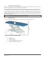
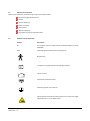
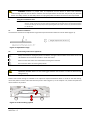
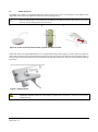
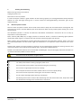
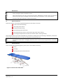
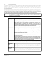
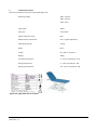
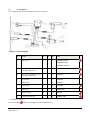
Lojer Capre-series
examination tables
Operating and maintenance manual
13.8.2012 1.0
Contents
1
Lojer Capre-series examination tables ................................................................................................................1
1.1
Description of parts ....................................................................................................................................... 1
1.2
Options and accessories ................................................................................................................................ 3
1.3
Symbols used on the device .......................................................................................................................... 3
2
Introduction .......................................................................................................................................................4
2.1
Inspection upon delivery ............................................................................................................................... 4
2.2
Before use ...................................................................................................................................................... 4
3
Using the examination table ..............................................................................................................................5
3.1
Maximum inclination ..................................................................................................................................... 5
3.2
Cental locking of the castors (optional) ......................................................................................................... 5
3.3
Height adjustment ......................................................................................................................................... 6
3.4
Adjustment of the back rest .......................................................................................................................... 7
3.5
Adjustment of the heel support (Capre EG) .................................................................................................. 8
3.6
Using the bowl (Capre EG) ............................................................................................................................. 8
3.7
Paper roll holder (accessory) ......................................................................................................................... 8
3.8
Leg support (accessory) (Capre EG) ............................................................................................................... 9
3.9
IV-pole (option).............................................................................................................................................. 9
4
Cleaning and disinfecting ................................................................................................................................. 10
4.1
Metal and plastic surfaces ........................................................................................................................... 10
5
Maintenance .................................................................................................................................................... 12
5.1
Biannual measures ...................................................................................................................................... 12
5.2
Annual measures ......................................................................................................................................... 12
5.3
Troubleshooting .......................................................................................................................................... 13
5.4
Preventive maintenance .............................................................................................................................. 14
6
Technical information ...................................................................................................................................... 15
6.1
Circuit diagram ............................................................................................................................................ 16
6.2
Standards ..................................................................................................................................................... 17
7
Recycling .......................................................................................................................................................... 17
8
Contact information ......................................................................................................................................... 18
To avoid injury, follow the instructions given in this document.
Copyright © Lojer Oy, 2012
08/2012 Rev. 1.0
1
Lojer Capre-series examination tables
Lojer Capre E examination tables are intended for healthcare professionals in hospitals and clinics. The examination
tables are designed to be used a range of examination and procedure use.
The series contains three models: Capre E1 General examination table, Capre E2 General examination table and Capre
EG Gynaecological examination table. Model E1 has a 1-part table top. Model E2 and EG have a 2-section table top.
This document gives instructions for operating and maintaining Lojer examination tables. Please familiarise yourself
with these instructions before using the table. Use the device only as described and for the specified applications.
Store these instructions in an appropriate way, making sure that the instructions are available to all possible users
throughout the life of the device.
To avoid injury, follow the instructions given in this document.
1.1
Description of parts
The sections of Lojer Capre examination tables are shown below (Figure 1, Figure 2 and Figure 3).
Figure 1: Lojer Capre E1 examination table
1
2
3
4
5
Table top
Castors (accessory)
Central locking pedal
Place free height adjustment bar (accessory)
IV-pole mounting adapter (accessory)
Copyright © Lojer Oy, 2012
08/2012 Rev. 1.0
1
Figure 2: Lojer Capre E2 examination table
1
2
3
4
5
6
Back section
Leg section
IV-pole mounting adapter (accessory)
Castors (accessory)
Central locking pedal
Place free height adjustment bar (accessory)
Figure 3: Lojer Capre EG gynaecological examination table
1
2
3
4
5
6
7
8
9
Back section
Leg section
IV-pole mounting adapter (accessory)
Castors (accessory)
Central locking pedal
Place free height adjustment bar (accessory)
Bowl
Heel support
Leg support (accessory)
Copyright © Lojer Oy, 2012
08/2012 Rev. 1.0
2
1.2
Options and accessories
Options and accessories available for Lojer Capre examination tables:
Place free height adjustment bar
Castors
IV-pole adapter (2)
Paper roll holder
Neck cushion
SKAI Lux upholtery
Leg supports (only for Capre EG model)
1.3
Symbols used on the device
Symbol
Description
CE
This product meet the requirements of Medical Device Directive
93/42/EEC
IPX4
Protected against liquids (electrical equipment)
B type device
Transformer is equipped with overheating protection.
Indoor use only.
Protectively isolated structure
Protective ground (class I-device)
Warning labels (squeezing hazard) placed on the place free height
adjustment bar or on the lower frame.
Copyright © Lojer Oy, 2012
08/2012 Rev. 1.0
3
2
Introduction
2.1
Inspection upon delivery
Before the device is taken into use, check that the packaging is intact and that it has not been damaged during
transportation. Please notify the transport company and the supplier of any transit damage within two (2) days of
receiving the delivery.
Ensure that the delivery contains all the parts detailed in the delivery note. If there is anything missing from the
delivery consignment, please contact the supplier immediately.
The device can be stored at a temperature of -5...+60 °C. The permitted humidity is 30...75 %.
2.2
Before use
The device is intended to be used in normal, dry indoor conditions. Ensure that the temperature of the room is
between +10…40 °C and the humidity is within the range of 30…75 %. If there is chance that device has been exposed
to temperatures below 0°C, allow it to adjust to the indoor temperature for at least 5 hours before using any of its
features.
Familiarise yourself with the instructions and carry out the following before using the table:
Make sure that all packing materials have been removed.
Make sure that the device can freely move up and down.
Place the device in the location where it will be used and lock the castors.
Connect the power plug to a socket whose supply voltage corresponds to the voltage shown on the
device’s type plate. Make sure that the cord runs freely from the connection box.
For safety reasons always connect the power cord to grounded socket.
Do not bind the power cord to the device as the lifting motion can severe the cord. Ensure that the
cord is easily detachable in an emergency situation.
Make sure that the distance to the socket is not more than 2 meters.
Always detach the power cord before moving the device. Make sure that the cord doesn’t get stuck
between parts of the frame or under the castors.
If the power cord is damaged, unplug it immediately. Do not use the device and contact the service.
Use only the original power cord.
Make sure that the patient doesn’t accidentally move/touch the place free bar or any other control
device.
Do not place anything under the device (e.g. chair, because the device has to be able move freely).
Make sure that the patient’s limbs do not get caught in the frame of the device.
Do not place the device under any wall structures or too close to the wall.
Do not modify the structure of the device or install parts other than those mentioned in this
document.
Do not use the device or the accessory if it doesn’t work properly. Contact the service.
Do not push the device on to a door sill.
Copyright © Lojer Oy, 2012
08/2012 Rev. 1.0
4
WARNING! Children or people with no experience of the device or those with restricted
understanding must not use the device. Children must be supervised to ensure that they do not play with the
device! For safety reasons use the safety switch or unplug the power cord when the device is left unsupervised.
3
Using the examination table
Note!
3.1
Do not use the electrical functions of the device non-stop for longer than the permissible two (2)
minutes. Longer continuous use may cause the transformer to overheat. If you use electrical functions
non-stop for two (2) minutes, keep to the operating time ratio and do not use any electrical functions
for 18 minutes.
Maximum inclination
The maximum inclination and adjustment range of the Capre examination tables are shown below (Figure 4).
Figure 4: Adjustment range
3.2
Cental locking of the castors (optional)
Always remember to unplug the power cord before moving the device. Make sure that the cord is not
left between the structure of the table or under the castors.
Make sure that the castors are locked before starting the treatment.
Do not use the device for moving the patients.
SQUEEZING HAZARD! Make sure that nothing gets between the structure or under the device during
lifting/lowering.
Castors with central locking are available as an option for Capre examination tables. In order to free the locking,
refract the pedal on either side of the table and press it down (Figure 5). To set ready for use, release the pedal and
refract it back to its position.
Figure 5: Central locking system
Copyright © Lojer Oy, 2012
08/2012 Rev. 1.0
5
3.3
Height adjustment
The height of the table can be adjusted with foot control (Figure 6 a)) or hand control (Figure 6 b)). Height can be
adjusted also with place free height adjustment bar (accessory) (Figure 6 c)).
Make sure that under no circumstances the patient is not able to touch the foot control or the place
free bar. Use the safety switch when necessary.
a)
b)
c)
Figure 6: a) foot control b) hand control c) place free hand control
Tables with place free height adjustment bar are equipped with safety switch (Figure 7) which makes it possible to
disconnect the power supply. Disconnecting is done by turning the pointer to the left (lock). Use the safety switch in
order to make sure that the patient won’t accidentally touch the control devices or when you leave the device without
supervision.
Figure 7: Safety switch
SQUEEZING HAZARD! Make sure that nothing is between the structure or under the device during
lifting/lowering.
Copyright © Lojer Oy, 2012
08/2012 Rev. 1.0
6
Height adjustment is possible from all sides of the table with the place free height adjustment (Figure 8). The table top
rises when you move the bar towards the head section of the table. The table top lowers when the bar is moved
towards the leg section
Figure 8: The place free height adjustment bar at the back of the table
The place free height adjustment bar can only be operated by pushing and pulling. Do not press it
down or place your entire weight on it.
SQUEEZING HAZARD! Make sure that under no circumstances the patient is not able to touch the foot
control or the place free bar. Use the safety switch when necessary
WARNING! Children or people with no experience of the device must not use the device. For safety
reasons use the safety switch or unplug the power cord when the device is left without supervision.
3.4
Adjustment of the back rest
Models E2 and EG can be adjusted electrically with a hand control (Figure 9)(1). The adjustment range is 0…78°.
Figure 9: The adjustment of the back rest
SQUEEZING HAZARD! Make sure that nothing is between the structure or under the device during
lifting/lowering.
Copyright © Lojer Oy, 2012
08/2012 Rev. 1.0
7
3.5
Adjustment of the heel support (Capre EG)
Capre EG is equipped with length adjustable heel supports (Figure 10). Lift the support while pulling/pushing it in
order to adjust. Lower the support and pull/push it so that it is locked in position. There are 5 locking holes on the
support.
Figure 10: Heel support
Make sure that the support is properly locked
3.6
Using the bowl (Capre EG)
Capre EG is equipped with a bowl (Figure 11). The bowl turns steplessly under and out of the table top. The bowl can
be removed by first turning it outwards and lifting it from the holder.
Figure 11:The bowl (Capre EG)
3.7
Paper roll holder (accessory)
The paper roll holder is located at the head end of the table (Figure 12). Two screws and nuts are supplied with the
holder. Use the screws to fasten the holder to the cross beam.
Figure 12: Paper roll holder
Copyright © Lojer Oy, 2012
08/2012 Rev. 1.0
8
3.8
Leg support (accessory) (Capre EG)
Leg supports are available as an accessory for Capre EG model (Figure 13). Adjust the height and width if necessary
with the lever 1. Make sure that the lever is properly tightened. After tightening turn the lever as seen in Figure 13 by
pushing the button (2) on the lever. This ensures the proper locking of the lever. Open the screw (3) and rotate the
cushion to suitable inclination. Tighten the screw.
Figure 13: Leg supports (Capre EG)
3.9
IV-pole (option)
Adapters for IV-pole are available as an option for all Capre examination table models. Adapters are located on the
both sides of the table (Figure 14,(1)). Install the pole to the adapter and lock it by releasing the lever (2). Lift the
release ring on the pole (3) to adjust the height. Release the ring to lock the pole on the suitable height.
Figure 14: IV-pole
Make sure that the IV-pole won’t hit anything when adjusting the height of the table. Remove all
accessories when moving the table.
Copyright © Lojer Oy, 2012
08/2012 Rev. 1.0
9
4
Cleaning and disinfecting
Before cleaning remove all accessories.
Unplug the power cord.
Clean stains as soon as possible.
In order to keep the surfaces in good condition do the cleaning regularly. Do cleaning/disinfectant always between
patients. Do more thorough cleaning once a month. Follow the cleaning/disinfecting instructions given by the
respective facility.
4.1
Metal and plastic surfaces
Clean the metal and plastic surfaces and the hand controls with a damp cloth and weak alkaline cleaning fluid. Use
small brush for corners and other difficult spots. Rinse with clean water and dry carefully after cleaning. Do not use
excessive fluids.
Use disinfectant (alcohol or chlorine) and follow the disinfectant manufacturer’s instructions for use. Let dry by
evaporation in room temperature.
Plastic surfaces (ABS, HDPE, PP) are highly resistant to chemicals. Plastic is resistant to bleaching agents (alkaline
compounds), dilute organic or inorganic acids. Also solvents and cleaning agents may be used.
Plastic surfaces may get damaged if aromatic hydrocarbons (benzene and its derivates), ketones, ethers, esters and
chlorinated hydrocarbons are used. Plastic might also deteriorate if it is exposed to various chemicals at the same
time.
Stainless steel surfaces are highly resistant to chemicals. Use for mild detergent solution for cleaning. Ammonia and
most of the solvents can be used to remove difficult stains. Avoid chlorine based solutions.
Painted or chromed metal surfaces can be cleaned with mild detergent. They are also highly resistant to chemicals. Do
not use harsh abrasive powders on these surfaces.
All surfaces must be dry before using the device.
For safety reasons before cleaning unplug the power cord.
Do not use water spray (shower, high-pressure water guns) for cleaning.
Do not clean in high temperature and air humidity.
Do not expose the device to excessive moisture which can result in liquid pooling.
Do not use solvents or petrol for cleaning. Do not use acids for cleaning.
Dry all surfaces thoroughly after cleaning or disinfection.
Disinfecting wears out the surfaces. After disinfecting clean the surfaces with clean, damp cloth. Dilute
the disinfectant according to the manufacturer’s instructions.
Copyright © Lojer Oy, 2012
08/2012 Rev. 1.0
10
Skai-material:
PROPERTIES:
LONG SERVICE LIFE
FLAME RETARDANT
AGREEABLE IN USE
RESISTANT TO DISINFECTANTS
ABRASION RESISTANT
TEAR-RESISTAMT
EASY TO CLEAN
DURABLE
LIGHT FAST
*Prescribed by law
Please follow the instructions of the respective manufacturer when using common cleaners.
Do not use oil or grease based solutions.
Do not use chemical or dry cleaning on the material.
The material is not resistant to solvents, chlorides, washing/polishing agents or aerosol sprays.
Colourings (by jeans or other textiles) are excluded from any guarantee.
Cleaning and disinfecting of the upholstery material
For hygienic reasons cover the upholstery with protective cloth or paper.
Remove any stains as quickly as possible with lukewarm water and a damp cloth. Microfiber cloth is recommended for
this purpose. In case of heavy soiling, use a mild cleaning agent and soft brush.
Recommendable cleaning agent: Lojer Desiplint (1:10), which is effective against bacteria without drying the
upholstery material.
Repeat the cleaning procedure if necessary. (Composition of Lojer Desiplint: Chlorhexidine-digluconate 0,1 – 0,2 %,
water 99,8 %.)
Use the recommended disinfectants (see matrix www.lojer.com). Lojer cannot be held responsible for the effects of
other solutions than those mentioned in the matrix. Wipe the surface with a clean, damp cloth after disinfecting.
Dried substances or substances that have penetrated for an extended period may not be able to be removed
completely.
Copyright © Lojer Oy, 2012
08/2012 Rev. 1.0
11
5
Maintenance
Always unplug the power cord before service.
Only trained person may carry out service and repair. Maintenance carried out by an authorized
person may cause injury or damage to the device which the manufacturer is not responsible for.
All service and repair operations must be documented.
5.1
Biannual measures
Check the condition and functioning of following parts at least every six months.
Power cord and its fastening.
The wiring of the motors.
Controls and their wiring.
The fastening of the accessories.
The fastening of the castors. Proper functioning of the central locking.
Go through all adjustment and make sure that the table is working correctly.
Stop using the device if you notice any defects e.g. the device is making noise or functioning in sufficiently. Contact the
service. Only authorized personnel can open or change the actuator/control unit.
If some part of the device is damaged, detach the power cord and stop using the device. Contact the
service.
5.2
Annual measures
Check and lubricate the following parts () once a year or more often if necessary.
Joints
Bearings
Bearing points of the underside rods
Figure 15: Parts to be lubricated
Copyright © Lojer Oy, 2012
08/2012 Rev. 1.0
12
5.3
Troubleshooting
Indication
Defect
Action
One of the actuators
doesn’t work
The
wiring
is
damaged or loose.
Check the fastening and condition of the wirings.
Defective
foot
control or place free
bar.
Check the control operation by testing with similar working foot
control. Change the foot control if necessary. Contact the service
Defective actuator.
Contact the service.
Defective
box.
control
Contact the service.
Defective
control
foot
Any of the actuators
won’t work.
No power
Defective
cord
Device is making noise
Check the control. Contact the service
Check that the power cord is properly plugged.
power
Check the cord and contact the service.
Defective relay
Contact the service.
The lubrication of
the joints has worn
out.
Lubricate the joints.
The actuator is worn
out or overloaded.
The actuator might stop working. Contact the service.
In order to change the actuators, control or control box and ordering spare parts contact the Lojer service. Before
contacting the service, find out the following information from the type plate of the device.
Name, model and the serial number of the device
Date of purchase
Description of the problem
Copyright © Lojer Oy, 2012
08/2012 Rev. 1.0
13
5.4
Preventive maintenance
The electrical characteristics and normal operation of the device should be performed according to the EN 62353
standard. In order to maintain the performance of the device, tests should be executed at least every 3 years.
Electrical equipment should be inspected by an approved service technician or some other party approved for
servicing medical devices.
EN 62353 applies to testing of medical electrical equipment during maintenance, inspection and servicing to assess
the safety of the devices. Tests should be performed by a qualified personnel. Qualification should include training,
knowledge and experience with the relevant test procedures, technologies and regulations. The personnel assessing
the safety should be able to recognize possible consequences and risks related to non-conforming devices.
Tests performed by non-qualified personnel might cause injury or damage to the device which the
manufacturer is not responsible for.
PROTECTIVE
EARTH
RESISTANCE
LEAKAGE
CURRENTS
Test is performed only for Class I equipment. All accessible conductive parts should
be included into test. Measurement current should be 200 mA. The total resistance
should not exceed 0,3 Ω.
Detachable power cords kept ready for use should be measures as well. Their
resistance should not exceed 0,1 Ω.
Before testing check the earth conductors and change them if necessary. Test is
performed between the protective earth connector of the mains plug and
protectively earthed accessible conductive part. The measured resistance should not
exceed 0,2 Ω. Test both the potential equalization point and the frame.
If the device is disassembled or the protective earth conductors have been changed,
protective earth resistance should be measured from various points.
The measuring device should be appropriate for testing leakage currents.
Detach the power cord of the medical device and connect it to the measuring device.
Attach the protective earth measurement lead to the point under test (change
points if necessary). Attach the applied parts to the measuring device. (Note! In Class
I equipment a leakage current measurement can be performed only after the
protective earth testing has been passed.)
Use the correct measurement method and procedures related to that.
Currents to be measured:
Equipment leakage current (current from the mains part to earth through protective
conductor and accessible parts and applied parts): Class I, type B applied part 500µA.
Applied part leakage current (current from the mains part and the accessible parts to
applied parts of the device): Class I, type B applied part 5000µA.
EVALUATION: The evaluation of safety of the tested equipment should be performed by electrically
skilled person, who has the appropriate training for the equipment under test.
FUNCTIONAL
TEST
REPORTING OF
RESULSTS
Copyright © Lojer Oy, 2012
08/2012 Rev. 1.0
Perform the procedures mentioned in Section Virhe. Viitteen lähdettä ei löytynyt..
Go through all functions in order to make sure that the device is working correctly.
Stop using the device if you notice any defects e.g. the device is making noise or
functioning in sufficiently. Contact the service.
All test performed should be documented. The documentation should include at
minimum the identification of the testing organization, name of the person who
performed the tests, identification of the equipment, details of the tests, date and
the result of the functional tests and measurements.
14
6
Technical information
Check the information also from the type plate (Figure 16).
Operating voltage
230 V ~50 Hz or
100 V ~50 Hz or
120 V ~50 or
Input power
230 W
Duty cycle
2 min/18min
Ingress protection rating
IP54
Medical device classification
Class I, type B applied part
(Safe Working Load)
210 kg
Width
68 cm
Length
E1,2 199 cm; EG 197 cm
Weight
105kg
Transport temperature
-5…+60 °C, humidity 30…75 %
Storage temperature
-5…+60°C, humidity 30…75 %
Operating temperature
+10…+40 °C, humidity 30…75%
Figure 16: Type plate and its location
Copyright © Lojer Oy, 2012
08/2012 Rev. 1.0
15
6.1
Circuit diagram
Circuit diagram of the examination tables are shown in Figure 17.
Figure 17: Circuit diagram
Nro
Nimitys
E1
E2
EG
Koodi
1
Control box
o
o
o
R284CB09K (230V)
R284CB09J (100V)
R284CB09120 (120V)
2
Safety switch (related to place
free height adjustment
x
x
x
R284ACL
3
Switch box (related to place
free height adjustment)
x
x
x
R282200S
4
Hand control
x
o
o
R284HB82
Foot control
o
x
x
R284FSE1
5
Junction box
o
o
o
R284DJBD
6
Power cord
o
o
o
R284HO5VV-F
7
Lifting actuator
o
o
o
R28434S
8
Actuator for back rest
-
o
o
R284LA31.4BP
o = standard, x = accessory
Parts marked with
needs to be changed by an authorized personnel.
Copyright © Lojer Oy, 2012
08/2012 Rev. 1.0
16
6.2
Standards
The device is in conformity with essential requirements of the Directive 93/42/EEC (Medical devices) and the
corresponding Finnish National Law no. 629 (2010). The device is marked with CE marking. The device is classified as
Class I medical device according to the directive.
7
Recycling
Most of the materials used in the device are recyclable. When the device is removed from usage, it should be
dissembled and recycled appropriately. Recycling should be done by specialized company. Do not dispose the device
in the household waste.
Remove the battery from the device. The oil from the hydraulic system should be removed and disposed
appropriately. Gas springs should be unpressurised and oilfree before recycling.
Following materials should be separated before recycling:
METALS: frame, screws, nails, springs etc.
ENERGY WASTE (combustible waste): wood and wood-based materials.
ELECTRIC WASTE: wires, power cords, actuators etc.
HOUSE HOLD WASTE: plastic, upholsteries and other materials which cannot be separated
further.
Contact your local disposal authority for more details of how to recycle. Follow the instructions given in local
collection points.
Copyright © Lojer Oy, 2012
08/2012 Rev. 1.0
17
8
Contact information
Manufacturer
Service
Lojer Oy
Tel. 010 830 6750
P.O. Box 54, Putajantie 42
Email: [email protected]
FI-38201 Sastamala
Tel.. +35810 830 6700
Fax. +35810 830 6702
Email: [email protected]
[email protected]
www.lojer.com
Your local Lojer dealer, see www.lojer.com/distributors
Model: ________________________________________________________
Serial number: __________________________________________________
Date of purchase: ________________________________________________
Your local Lojer dealer:____________________________________________
Copyright © Lojer Oy, 2012
08/2012 Rev. 1.0
18