1
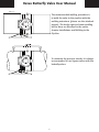
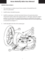
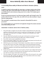
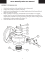
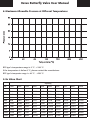
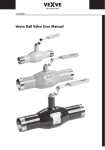
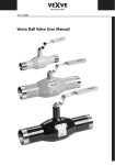
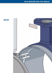
30.03.2010
Vexve Butterfly Valve User Manual
∆p = PN 25
∆p = PN 20 (DN 1200)
Vexve Butterfly Valve User Manual
Table of Contents
1.
General
2.
General Instructions and Cautions
3.
Valve Markings
4.
Valve Transportation and Storage
5.
Installations and Welding to the Pipeline
6.
Commissioning
7.
Maintenance
7.1 Assembly/Disassembly of Manual Gears (ProGear and Rotork)
7.1.1 Manual Gear Adjusting (ProGear and Rotork)
7.2 Assembly/Disassembly of Manual and Electric Actuators (Auma)
7.2.1 Manual Gear Adjusting (Auma)
7.2.2 Electric Actuator Adjusting (Auma)
7.3 Assembly/Disassembly of Pneumatic Actuators
7.4 Changing the O-rings (BFS/BRS types)
7.5 Tightening the Stem’s Graphite Packing (BFC/BRC types)
8.
Maximum Allowable Pressure at Different Temperatures
9.
Kv Value Chart
10. Construction drawing
1. General
Vexve butterfly valves are specially designed for the district heating pipeline closing (type BFS
and BRS) and control (type BFC or BRC) applications. Vexve BFC type butterfly valves can also be
used in steam applications. When using the valves in other applications or with other medium,
please consult with the manufacturer on the suitability.
The valve body is pressure equipment steel. The shafts and discs are manufactured from the
stainless steel material. The disc seal material is a nickel alloy based super steel material. The
stem/shaft sealing is done either O-rings (BFS/BRS Types) or graphite ring packing (BFC/BRC
Types) depending on the end application. The valve is bi-directionally tight. The valve opens when
turning the manual gear to clockwise. The position indicator line at the end of the stem shows
the disc’s position versus the stem.
Vexve Oy is not responsible for the damages caused by unknown subjects or dirtiness. Vexve Oy
is also not responsible for the damages caused by the improper handling or delivery.
2
Vexve Butterfly Valve User Manual
2. General Instructions and Cautions
Please read and notify the following instructions before handling and operating the Vexve
butterfly valves:
• The valve should be lightly closed during the storage.
• Do not lift the valve on the actuator or on the gear. Please follow the instructions
from the page 5 (valve lifting).
• The weight of the valve should always be taken care when handling the valve.
• Beware of the discs cutting movement! The disc creates a cutting motion with its sharp angles
during the valve closing.
• The valve may cause noise at the pipeline! Be protected against the noise.
• The manual gear or actuator may not been removed or dismantled if the valve is pressurized.
It is recommended to use a special tools and equipment (designed for actuator removal)
when disassembling the valve.
• The shaft (O-ring or graphite) packing may not be dismantled when the valve is pressurized.
• The valve may not be used alone as a pipeline ending fitting. Always after the valve a blank
flange needs to be welded or/and connected to the pipeline end. The space between the
flange and the valve should be filled with oxygen-free water.
• Do not exceed the manufacturer’s informed maximum closing torques.
• Do not exceed the manufacturer’s informed maximum temperature and pressure ranges
(sated at the valve identification plate).
• Do not use unnecessary power to turn the manual gear spindle and closing the valve.
The position indication line at the top of the stem shall not be more than maximum
2 degrees over the closing position.
• The installed valve at pipeline can be extremely hot! Be protected to different temperatures.
3
Vexve Butterfly Valve User Manual
3. Valve Markings
The identification plate locates at the actuator flange’s side. It has the following information:
1
2
0575
9
10
3
4
5
6
7
8
BFS0600W2
0001001
25
25
11
12
15
2004
200
-40
13
1.
Valve Manufacturer
2.
Individual Valve Number
3.
Valve Type B = Butterfly valve
4.
Product Group F = Full Bore R = Reduced Bore
5.
Valve Function S = Shut-Off Valve C = Control Valve
6.
Valve Size (DN)
7.
Connection to the pipeline W = Welding Ends F = Flanged Ends
8.
Maximum pressure difference: 1 = 16 bar, 2 = 25 bar
9.
Russian Valve Certification
10. CE-Mark and the number of the notified body
11. Pressure Class
12. Approved maximum pressure difference when valve is closed
13. Approved minimum operational temperature
14. Approved maximum operational temperature
15. Manufacturing Year
4
14
Vexve Butterfly Valve User Manual
4. Valve Transportation and Storage
Please check that the valve or its parts are not damaged during the transportation. Please also
check that the content of the delivery (valve types, sizes, etc.) is according to the agreement. The
information on the possible damages or deviations in the content must be immediately informed
to Vexve Oy.
Store the valve at clean and dry storage before the installation. Do not remove the flow port
protectors before the installation.
During storage the valve must be lightly closed.
Lift the valve as shown in the picture. Do not lift the valve from its actuator or stem.
NOTE!
The weight of the valve should always be taken care when handling the valve.
Please be careful when closing the disc. The disc creates a powerful cutting motion with its
sharp edges during the valve closing.
5
Vexve Butterfly Valve User Manual
5. Installations and Welding to the Pipeline
The valve may only be installed to places where it is designed and applicable. Do not exceed the
valve performance limitations! The maximum operational pressures and temperatures can be
found from the valve identification plate.
Do not remove the manual gear or actuator from the valve. If the manual gear or
actuator needs to be removed during the installation, please follow the actuator manufacturer’s
instructions how to adjust the actuator when reassembled (chapter 7).
Remove the valve flow port protectors before the installation. Check that the valve is undamaged
and clean inside. Close the valve during the welding.
It is recommended to install the valve to the pipeline according to the preferred flow direction
arrow.
Picture 1
Picture 2
Special Instructions – Corners/Elbows & Pumps
After corners and centrifugal pumps the pressure on the outer edge is higher than on the inner
edge. When installing the butterfly valve immediately after a pipe elbow, we need to install the
valve to the pipeline so that the shaft is directly at a 90-degree angle to the corners’ middle point
(perpendicular) (please see picture 1).
When installing the valve after centrifugal pump, the valve shaft needs to be perpendicular (at a
90 degree angle) to the pump shaft (please see picture 2).
It is always recommended to install the valve so that the valve shaft is in horizontal position. This
minimizes the forces to the valve disc’s bearings. However, if two (2) valves are installed in-line
in close proximity, then the valve shafts need to be at a 90 degree angle (perpendicular) versus
each other.
6
Vexve Butterfly Valve User Manual
1
3
4
Picture 1
2
Picture 2
Electric welding is used when welding the valves to the pipeline.
If the valve is welded to vertical pipeline, close the valve and cover it at least with 4cm water
cushion. This water cushion will then ensure that the welding spatters from the welding
procedure cannot damage the sealing and disc surfaces (picture 1).
The valve should be first welded to the pipeline by using the bridge spot welding: by welding 4-8
pieces of 5cm seams across the valve (up-down-left-right, etc.). After that the seams between the
bridges are welded as shown at the picture (picture 2).
Valve may not be used as a line ending fitting alone. Always after the valve a blank flange needs
to be welded or/and bolted to the pipeline. Also the backside empty space needs to be filled
with water with no oxygen to prevent the corrosion.
The possible lid welding has to be minimum 200mm distance from the valve welding seams.
7
Vexve Butterfly Valve User Manual
500 mm
The recommended welding procedure is
to weld the valve to the pipeline with the
welding extensions (please see the attached
picture). The bridge spot and seam welding
will be done as described in the earlier
chapter Installations and Welding to the
Pipeline.
To minimize the pressure shocks, it is always
recommended to use bypass valves with the
butterfly valves.
8
Vexve Butterfly Valve User Manual
6. Commissioning
The pipeline needs to be flushed carefully after the valve installation. Close the valve during the
flushing until the disc is open app. 5 degrees. The small angle’s increased flow cleans efficiently
the possible contamination from the valve’s sealing surfaces.
During the commissioning, the valve opening will be set to app. 15 degrees to minimize the
potential pressure shocks’ impacts to the valve.
The largest allowable testing pressure is 1,1xPN, when the valve is closed.
During the pipeline pressure testing (1,5xPN), the valve needs to be open.
When installing the BFC valve type, the tightness of the graphite packing needs to be checked.
If needed to tighten the packing to stop the stem leakage, tighten the hexagonal packings
tightening screws (please look the chapter 7.5). Do not tighten the packing too much due it will
increase the valve torque.
Do not exceed the manufacturer’s informed maximum allowable torque values.
7. Maintenance
When preparing for the maintenance, please note that the valve’s surface temperature can
be dangerously high when the valve is installed to the pipeline. Be prepared against the
potential accidents (burns, etc.).
9
Vexve Butterfly Valve User Manual
7.1 Assembly/Disassembly of Manual Gears (ProGear and Rotork)
NOTE!
It should be avoided to disassembly the manual gear or actuator, due the valves closing
torques are fine-tune in the position where the valves have the best tightness. There is
a possibility that the valve actuator settings needs to be re-done if the actuator/gear is
disassembled.
Do not use unnecessary power to turn the manual gear spindle and closing the valve. The
position indication line at the top of the stem shall not be more than maximum 2 degrees
over the closing position.
The manual gear or actuator may not been removed or dismantled if the valve is
pressurized.
It is recommended to use a special tools and equipment (designed for actuator removal)
when disassembling the valve.
Disassembly of the Manual Gear
1. The manual gear or actuator may not been removed or dismantled from the valve if the
pipeline is pressurized. The gear operates as opening and closing stopper at the butterfly valve. At
the valve itself there is no stoppers. The gears used at butterfly are so called self-holding gears.
2. Close the valve fully (by using the manual gear), for during the manual gear removal (The
valve will be closed to the clockwise direction). The spindle is attached to the axial with the pin
(4). The pin is designed so that it will break in pieces if too large torque and power is used when
handling the gear. This will ensure that the gear itself will not be damaged.
3. Turn the gear/actuator slightly open to decrease the torque and power from the valve and the
gear. This will enable the gear spindle to move easily.
4. Before the gear removal, the gear’s bush adapter’s (1) position needs to be marked against the
valve shaft. Remove the position indicator plate (3) by disassembling the fastening screws (2),
to be able to see the gear’s bush adapter and shaft. At the ProGear manual gear the bush is a
separate and at the Rotork manual gears the bush’s shape is machined directly to the gear.
5. Remove the bolts and pull the gear out of its place. If needed, use the dismantle tool by
setting the tool’s axis to the top of the stem and the tool’s lugs on the bottom of the actuator.
10
Vexve Butterfly Valve User Manual
Manual Gear Assembly
1. The manual gear or actuator may not been removed or dismantled from the
valve if it is pressurized.
2. Install the key to the shaft’s key place.
3. Install the manual gear so that the hand wheel locates at the preferred position.
Check that the shaft is either at the original position or 180 degrees against the original
position. If so, then there is no need for fine-tuning and re-positioning of the actuator.
If a new actuator or gear is assembled, then the actuator needs to be set and positioned
as described in the chapter 7.1.1.
4.
Install and tighten the bolts of the actuator/gear.
2
4
3
1
8
7
6
5
11
Vexve Butterfly Valve User Manual
7.1.1 Manual Gear Adjusting (ProGear and Rotork)
1.
Check that the valve has no flow and that the valve is depressurized.
2.
Close the valve fully and check that the gear is at the closed position.
3.
Install the key carefully to its location at the shaft.
4.
Install the gear so that the hand wheel comes to the preferred location.
5.
Install the handle to the gear.
6.
Crease, install and tighten the nuts of the manual gear’s bolts. If needed, turn the manual
gear’s wheel to match the holes of the gear and the actuator flange.
7.
Remove the position screws’ covers (5).
8.
Loosen the stop screws (6).
9.
Turn the hand wheel couple of times and open the closed position (7) and open
position screws (8) fully open.
10a. If the pipeline has no flow, the valve limits are set by using the torque key. At first, the
wheel of the gear is removed and the torque key attached to the gear’s shaft. The needed
torque values are available from Vexve Oy. Please inform the serial number of the valve from the valve identification plate. Please also inform the valve type.
10b If the pipeline has flow, then turn hand wheel as long as you can hear that there is no
flow at the pipeline. Do not use unnecessary power to turn the manual gear hand
wheel/spindle when closing the valve. The position indication line at the top of the stem
shall not be more than maximum 2 degrees over the closing position.
11. When the right closing position has been found, tighten the stop screw for closed position.
Then turn it back a 1/4 turn.
12. The stop screw will be locked up either with the locking screw (6) or with the locking
sealant (e.g. Loctite 225).
13. Turn the disc 90 degrees (to fully open position)
14. Tighten the stop screw for open position (8), and lock it with locking screw (6) or locking
sealant.
15. At the end, install the screw covers (5) to the top of the stop screws.
12
Vexve Butterfly Valve User Manual
2
4
3
1
8
7
6
5
13
Vexve Butterfly Valve User Manual
7.2 Assembly/Disassembly of Manual and Electric Actuators (Auma)
NOTE!
It should be avoided to disassembly the manual gear or actuator, due the valves closing
torques are fine-tune in the position where the valves have the best tightness. There is
a possibility that the valve actuator settings needs to be re-done if the actuator/gear is
disassembled.
Do not use unnecessary power to turn the manual gear spindle and closing the valve. The
position indication line at the top of the stem shall not be more than maximum 2 degrees
over the closing position.
The manual gear or actuator may not been removed or dismantled if the valve is
pressurized.
It is recommended to use a special tools and equipment (designed for actuator removal)
when disassembling the valve.
Disassembly of Manual and Electric Actuators (AUMA)
1.
The manual gear or actuator may not been removed or dismantled from the valve if the
pipeline is pressurized. The gear operates as opening and closing stopper at the butterfly
valve. At the valve itself there is no stoppers. The gears used at butterfly are so called
self-holding gears.
2.
Close the valve fully (by using the manual gear), for during the manual gear removal
(The valve will be closed by turning the wheel to the clockwise direction).
3.
Turn-off the electric power supply(electric actuators).
4.
Turn the gear/actuator slightly open to decrease the torque and power from the valve and
the gear. This will enable the gear spindle to move easily.
5.
Before the gear removal, the gear’s bush adapter’s (1) position needs to be marked against
the valve shaft. Remove the position indicator plate (3) by disassembling the fastening
screws (2), to be able to see the gear’s bush adapter and shaft. Remove then the locking
ring (4) by screwdriver, and remove the protection plate (5) to be able to see the stem
adapter bush.
6.
Remove the bolts and pull the gear out of its place so that the stem adapter bush will stay
at the bush. If needed, use the dismantle tool by setting the tool’s axis to the top of the stem and the tool’s lugs on the bottom of the actuator.
7.
If the stem adapter bush needs to be removed, the height of the bush needs to be marked
first to the stem. After marking, the tightening screw is opened (6) and the stem adapter
bush is removed by using the dismantle tool.
14
Vexve Butterfly Valve User Manual
Assembly of the Manual Gear
1.
Check that the valve has no flow and that the valve is depressurized.
2.
Install the key carefully to its location at the shaft.
3.
Install the stem bush adapter first to the original height (marked at the disassembly) and
tighten the screws (6) carefully.
4.
When assembling the manual gear, check that the stem bush adapter is in its original
position. There is no need to set the gear/actuator settings again when assembled to the
original position. If wanted to turn the gear/actuator 180 degrees, then the setting and fine-
tuning needs to be done according to the chapter 7.2.1.
5.
Install and tighten the bolts of the actuator/gear.
2
3
4
5
8
7
6
1
15
Vexve Butterfly Valve User Manual
7.2.1 Manual Gear Adjusting (Auma)
1.
Check that the valve has no flow and that the valve is depressurized.
2.
Close the valve and check also that the actuator is at off position.
3.
Install the key carefully to its location at the shaft, and push the bush (1) to its place. Look
the bush’s right level/height from the actuator/gear and tighten the tightening screw (6)
carefully.
4.
Install the manual gear so that the hand wheel comes to the preferred direction.
5.
Install the hand wheel to the gear if not attached.
6.
Crease, install and tighten the manual gears/actuators bolts so that the gear cannot move
against the actuator flange. If needed, turn the hand wheel to be able to get the boltholes
against each other (at flange and gear).
7.
Turn the hand wheel couple of turns to open the valves. Remove the limiting bush’s (8)
fastening screws (7) so the bush can turn freely.
8a. If the pipeline has no flow, the valve limits are set by using the torque key. At first, the wheel
of the gear is removed and the torque key attached to the gear’s shaft. The needed torque
values are available from Vexve Oy. Please inform the serial number of the valve from the
valve identification plate. Please also inform the valve type.
8b. If the pipeline has flow, then turn hand wheel as long as you can hear that there is no flow
at the pipeline. Do not use unnecessary power to turn the manual gear hand wheel/spindle
when closing the valve. The position indication line at the top of the stem shall not be more
than maximum 2 degrees over the closing position.
9a. Small Auma gears (<GS160).After finding the right closed position has been found, turn the
limiting bush slightly to clockwise direction to position where it does not move anymore.
Then turn back the bush app. 1/8 turn. Pull the bush out of its bores (app. 2cm) and install
the limiting bush back to its place so that the holes of the bush are in the line with the
gear’s holes.
9b. AUMA GS 160 and larger gears the limiting bush does not need to pull out of its bores.
In larger valves, the bush will be tightened directly to the right position with the flanges.
7.2.2 Electric Actuator Adjusting (Auma)
1-7 phases done as in the manual gear adjusting (see above chapter)
8. Do the electrical connections so that the actuator has the moment and electrical limit
switches in place. (at AUMA MAtic type the connections are done in advance at the factory)
9.
Connect the power to the actuator
10. Turn the valve open app. 45 degrees from its manual gear’s hand wheel. Push the open/
close buttons slightly to see that the valve turns to right direction. If the direction is wrong,
change the connections and check the opening/closing again. (3-way actuators)
16
Vexve Butterfly Valve User Manual
11a.If the pipeline has no flow, the valve will be calibrated with the help of torque values. At first,
open the gear’s lid and install the calibrating torque (you will receive this torque value from
Vexve Oy by informing the serial number and size of the valve from the valve identification
plate. Close the valve with this torque. Open the manual gear’s cover so that you can see
from the end of the shaft (line) has the valve closed totally. The line of the shaft will inform
the valve’s open or close position. The line needs to be directly against the pipeline.
11b.If the pipeline has flow, then turn the hand wheel as long as you can to hear that there is no
flow at the pipeline. Do not use unnecessary power to turn the manual gear hand wheel/
spindle when closing the valve. The position indication line at the top of the stem shall not
be more than maximum 2 degrees over the closing position.
12. When the valve is closed, set the electrical closed position limit to this position.
13. Set the mechanical limit at the same way as described at the chapter 7.2.1 (9a and 9b)
Manual Gear Adjusting (Auma).
14. Open the valve to the open position, and install the electric open limit slightly before the
mechanical limit.
15. When the limits are set and the valve returned to the middle position, install from the
moment switch the new so called maximum closing torque that you will receive from
Vexve Oy together with the calibrating torque.
2
3
4
5
8
7
6
1
17
Vexve Butterfly Valve User Manual
7.3 Assembly/Disassembly of Pneumatic Actuators
NOTE
The manual gear or actuator may not been removed or dismantled if the valve is
pressurized.
It is recommended to use the special tools designed for the actuator removal.
The pneumatic actuator removal and installation should be done according to the actuator
manufacturer’s instructions.
Manufacturers given maximum allowable torque values shall not be exceeded.
7.4 Changing the O-rings (BFS/BRS types)
The pipeline needs to be depressurized when changing the O-rings!
There is a special tool designed for the stem bush removal. Please contact the manufacturer
to receive the special tool for the O-ring change.
1.
The gear/actuator is removed according to the chapters 7.1, 7.2 or 7.3 instructions.
2.
Remove the key from the shaft.
3.
Release the retaining ring.
4.
Pull out the O-ring bushing with the help of the bushing removal tool.
5.
Crease the new O-rings with e.g. Wurth HHS2000 spray. Change the O-ring to the bush.
6.
Check that the key, shaft, or bush has no sharp corners that could damage the O-rings
when installing those. If needed, grind or use the adhesive tape.
7.
Push the O-ring bushing back to its place at the valve. Recommended to us the special tool.
8.
Install the retaining ring and key back to their places,
9.
Install the gear to its place according to the chapters 7.1, 7.2 or 7.3 instructions.
7.5 Tightening the Stem’s Graphite Packing (BFC/BRC types)
The valve does not need regular maintenance.
The BFC model has graphite packing and the packing should be checked on a regular basis. If
there is leakage from the stem packing, the stem packing should be tightened by tightening the
hexagonal tightening nuts/screws from the stem. The tightening screws and their location can be
seen from the construction picture (number 1 Hexagonal nut).
18
Vexve Butterfly Valve User Manual
8. Maximum Allowable Pressure at Different Temperatures
BFS type’s temperature range is 0 ºC…+200 ºC.
If the temperature is below 0 ºC, please contact the manufacturer.
BFC type’s temperate range is -40 ºC…+250 ºC.
9. Kv Value Chart
Opening
DN
10%
20%
30%
40%
50%
60%
70%
80%
90%
100%
350
306
611
917
1223
1879
2536
3582
4628
6014
7400
400
405
810
1214
1619
2489
3358
4743
6129
7964
9800
500
644
1289
1933
2577
3961
5345
7551
9756
12678
15600
600
938
1875
2813
3751
5764
7778
10987
14196
18448
22700
700
1293
2586
3879
5172
7948
10725
15150
19575
25437
31300
800
1681
3362
5043
6725
10335
13946
19700
25453
33077
40700
900
1904
3808
5713
7617
11707
15796
22313
28830
37465
46100
1000
2350
4701
7051
9401
14449
19497
27541
35585
46242
56900
1200
2685
5370
8055
10740
16506
22273
31461
40650
52825
65000
19
Vexve Butterfly Valve User Manual
Vexve Type BFC Construction
1. 2. 3. 4. 5. 6. 7. 8. 9. 10. 11. 12. 13. 14. 15. 16. 17. 18. 19. 20. 21. 22. 23. 24. Hexagonal nut 2 pcs
Base plate 2 pcs
Headless screw 2 pcs
Clamping bush 1 pcs
Slide bearing 1 pcs
Shaft packing 4 pcs
Bearing of the upper shaft 1 pcs
Key 1 pcs
Upper shaft 1 pcs
Identification plate 1 pcs
Pin 3 pcs
Disc 1 pcs
Disc seat 1 pcs
Lower shaft 1 pcs
Bearing of the lower shaft 1 pcs
Lock ring 1 pcs
Blind flange 1 pcs
Actuator base 1 pcs
Hexagonal nut 4 pcs
Base Plate 8 pcs
Hexagonal screw 4 pcs
Body 1 pcs
Positioner plate 1 pcs
Bearing plate 1 pcs
1
2
3
4
5
6
7
18
19
8
20
9
21
10
11
22
12
13
14
15
23
16
24
17
20
Vexve Butterfly Valve User Manual
Vexve Type BFS Construction
1.
2.
3.
4.
5.
6.
7.
8.
9.
10.
11.
12.
13.
14.
15.
16.
17.
Retaining ring O-ring bushing Key Identification plate Upper shaft Pin Disc Disc seat Lower shaft Bearing of the lower shaft Lock ring Blind flange O-ring Bearing of the upper shaft Body Positioner plate Bearing plate 1 pcs
1 pcs
1 pcs
1 pcs
1 pcs
3 pcs
1 pcs
1 pcs
1 pcs
1 pcs
1 pcs
1 pcs
4 pcs
1 pcs
1 pcs
1 pcs
1 pcs
1
13
2
14
3
4
5
15
6
7
8
9
10
16
11
17
12
21
Vexve Butterfly Valve User Manual
Notes
22
Vexve Butterfly Valve User Manual
Notes
23
Vexve Inc. • Pajakatu 11 • FI 38200 Sastamala, Finland
Tel. +358 10 734 0800 • Fax +358 10 734 0839 • [email protected] • www.vexve.fi