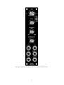
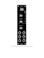
1
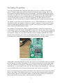
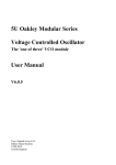
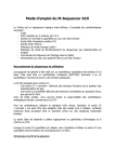
Oakley Sound Systems
5U Oakley Modular Series
Slim VCO A & Slim VCO B
Main PCB Issue 1, 1.1 & 2
User Manual
V2.0.1
Tony Allgood
Oakley Sound Systems
CARLISLE
United Kingdom
The suggested panel design for the SVCO A in standard MOTM format.
2
The suggested panel design for the SVCO B in standard MOTM format.
3
Introduction
This is the User Manual for both the A and B versions of the Slim Voltage Controlled
Oscillator 5U module from Oakley Sound. This document contains an overview of the
operation of the units and the calibration procedure.
For the Builder's Guides, which contain a basic introduction to the board or boards, a full
parts list for the components needed to populate the board or boards, and a list of the various
interconnections, please visit the main project webpage at:
http://www.oakleysound.com/s-vco.htm
For general information regarding where to get parts and suggested part numbers please see
our useful Parts Guide at the project webpage or http://www.oakleysound.com/parts.pdf.
For general information on how to build our modules, including circuit board population,
mounting front panel components and making up board interconnects please see our generic
Construction Guide at the project webpage or http://www.oakleysound.com/construct.pdf.
This is the prototype issue 1 Oakley SVCO-A module behind a natural finish 1U wide MOTM format
Schaeffer panel.
4
The Oakley SVCO-A and SVCO-B
Two compact well specified audio VCOs for MOTM and MU based modular synthesisers.
The 'A' variant has a single tune control and three way octave switch. While the otherwise
identical 'B' variant has an increment-decrement switching system (with three way momentary
switch and LED ladder display) to allow for easy control over five octaves and a wide range
LFO setting.
SVCO-A modules are built with just the SVCO main board. The B variant uses the same
SVCO main board with an additional SVCO-B daughter board that attaches to the main board
via a tidy 10-way ribbon cable.
Pitch is controlled by either a precision 1V/octave input socket or by a CV (control voltage)
input whose sensitivity is controlled by a front panel pot. The SVCO can also be connected to
the Oakley Buss for hassle free keyboard or sequencer control.
Both variants have a variable width pulse wave as well as a sawtooth waveshaper to generate
a fully varying shape from ramp through triangle to sawtooth. An external CV input may be
used to control the waveshape. The Shape CV input features a reversible attenuator control so
that the incoming CV may be inverted as well as simply level controlled.
The SVCO uses a sawtooth core but with a different topology than our existing double width
VCO. The core of the VCO circuit is based on designs used in a series of classic Japanese
synthesisers from the mid to late 1970s. However, it should be said that the SVCO does not
copy any particular synth but instead takes certain attributes from several of them. The pitch
control circuitry is a development of my usual design, while the sawtooth waveform shaping
is, to my knowledge, entirely unique.
Hard synchronisation is possible from an external VCO that has a falling edge sawtooth
output.
To allow all the functions required by this module we have had to reduce the spacing between
the pots. Instead of our usual 1.625" (41.3mm) we have opted for the smaller 1.375"
(34.9mm). Used in conjunction with smaller 20mm (13/16") diameter knobs this still allows
for an attractive module design and finger friendly tweaking.
The module accommodates either our standard Oakley/MOTM power header or a
Synthesizers.com power header. Current consumption is approximately +40mA and -35mA
for the SVCO-A, and +47mA and -38mA for the SVCO-B.
In LO mode the SVCO-B will act as a voltage controlled low frequency oscillator. In this
mode, and without any additional CVs patched in, the SVCO-B's frequency pot will operate
over a range of 0.01Hz (one cycle every 1.5 minutes) to around 500Hz. The SVCO-B will
always initialise in the LO mode on power up.
5
The Oakley CV/gate Buss
You really should think about using the Oakley Buss if you have a medium sized Oakley
system. Using the Oakley Dizzy board it allows the 'keyboard control voltage' (KCV) and
Gate signals to be piped around the back of the modular’s case along with the power supply
rails. Any VCO and VCF can be connected to the Oakley Buss's KCV line, and this will save
you having to patch KCV to every module that needs it. Inserting any patch lead into the
1V/OCT socket will override the CV bus line connection. The gate signals are treated
similarly to the KCV line but for use with the ADSRs and other envelope generator modules.
The Oakley CV/gate buss uses a common three way 0.1” Molex KK header to carry the two
signal lines around your modular. A third, as yet unused connection is also present for future
expansion, although typically this is taken to ground on the Dizzy board. More information
can be found in the Dizzy Builder's Guide.
The Oakley SVCO supports the Oakley CV/gate buss natively. The SVCO's main circuit
board features a three way header, labelled BUSS, that can be fitted to allow direct connection
to the CV/gate buss on an installed Oakley Dizzy system or to our VCO Controller module. If
not required, a simple two way jumper, like those used on computer motherboards, can be
fitted to connect between pins 1 and 2. By fitting this jumper the 1V/octave socket is shorted
to ground when a jack plug is not inserted thus reducing pick up from stray signals.
The Oakley Buss header with jumper inserted.
Although the Oakley Buss header is a three way connector the actual interconnect you need to
use has only one wire fitted. The Oakley VCO is connected only to pin 1 of the Oakley Buss.
This is the connection carrying KCV. This means you need to use only a single wire that is
terminated in a 3 way housing at either end. The first location of the housing, pin 1, is the only
one used with the other two locations being left empty and no other wires needed.
On no account should an interconnect with all three wires fitted be used to connect the Oakley
Buss to any module. The middle location, pin 2, is ground on the module and this should not
be connected to the Dizzy or midiDAC modules. Connecting the ground of a module to the
Dizzy ground in this way may induce earth loops and other problems.
6
Power supply requirements
The design requires plus and minus 15V supplies. The power supply should be adequately
regulated. The current consumption is about +40mA for the +15V rail and -35mA for the
-15V rail. Power is routed onto the PCB by a four way 0.156” MTA156 type connector or the
special five way Synthesizers.com MTA100 header.
Power connections – MOTM and Oakley
The PSU power socket is 0.156” MTA 4-way header. This system is compatible with MOTM.
Power
Pin number
+15V
Module GND
Earth/PAN
-15V
1
2
3
4
The earth/pan connection has been provided to allow the ground tags of the jack sockets to be
connected to the powers supply ground without using the module’s 0V supply. Earth loops
cannot occur through patch leads this way, although screening is maintained. Of course, this
can only work if all your modules follow this principle.
Power connections – Synthesizers.com
The PWR power socket is to be fitted if you are using the module with a Synthesizers.com
system. In this case the PSU header is not fitted. The PWR header is a six way 0.1” MTA, but
with the pin that is in location 2 removed. In this way location 3 is actually pin 2 on my
schematic, location 4 is actually pin 3 and so on.
Power
Location number
Schematic Pin number
+15V
Missing Pin
+5V
Module GND
-15V
Not connected
1
2
3
4
5
6
1
2
3
4
5
+5V is not used on this module, so location 3 (pin 2) is not actually connected to anything on
the PCB.
If the PWR header is fitted then pins 2 and 3 of PSU are linked together. This connects the
panel ground with the module ground.
7
Calibration
You should use a proper trimmer tool for the adjusting of all four multiturn trimmers. Vishay,
Bourns and others make trimmer adjusters for less than a pound.
Before you calibrate you should make sure that the HFT trimmer is adjusted so that the HFT
circuitry is turned off. To do this you must disconnect the module from the power supply and
then with a resistance meter measure between the right hand end of R45 and ground. The
easiest way to connect to ground is pin 3 of U6 for issues 1 & 1.1, or pin 9 of U6 for issue 2.
Turn the HFT trimmer until this reading drops to zero, or near zero, ohms.
Now power up the module and make sure it has been powered up for at least twenty minutes
prior to calibration. Also, it is a good idea to have the room temperature close to what it
would normally be when playing your modular.
SCL: This is the scale trimmer. Use this to generate a perfect 1V/octave scaling. This trimmer
will need to be adjusted along with the tune or frequency pot on the front panel. You will need
a digital frequency counter, or my favourite, a guitar/chromatic tuner or tuner plug-in. Some
people use another keyboard or a calibrated VCO and listen to the beats but that can take
some practice to do it right.
Plug your midi-CV convertor or 1V/octave keyboard into the 1V/OCT input of the SVCO. If
you have an SVCO-B module then use the INC/DEC switch to set the module to the 8”
setting. Play a lowish note on the keyboard, then play two octaves higher. Adjust SCL until
the interval is exactly two octaves. I normally try to work between the two As of 220Hz and
880Hz.
However, please note we are only setting the interval and not the actual frequency. It does not
have to be a perfect A when A is being pressed on the keyboard. It could be an F or whatever.
The important thing is that we are setting the musical gap between the notes. If you do need
to alter the pitch of the VCO use the front panel control only. Leave the TUN trimmer until
later.
For any interval, if you find the higher note is flat, then turn the SCL trimmer to make it flatter
still. This actually reduces the range between the two notes. Conversely, if you find your
interval is greater than an octave, turn the trimmer to make the top note even higher. I always
adjust SCL on the high note of any interval, and only adjust the front panel Tune pot on the
lower.
This will probably require some patience and plenty of twiddling of the front panel tune
control as well. But you will get there. Once you get the hang of it, its easy. I can do it in
about one minute but I’ve had a lot of practice.
You should be able to get it as accurate as +/-1 cent. But very low notes will be out by a little
more than this.
Now leave it on for a further 20 minutes and then check the scaling again. Adjust if necessary.
8
HFT: This is the high frequency tracking trimmer and it compensates for the slight flattening
of pitch at when running the VCO at high frequencies. If you don't go above 3kHz that often
there is a good chance you won't even have to touch this one. Like the SCL trimmer it will
have a small knock on effect on the absolute pitch of the SVCO lower down too.
If you only have a small keyboard use the keyboard's octave transpose setting and the
module's tune and octave controls to get the VCO playing a really high note. I work between
the two As of 7040Hz and 14,080Hz. However, you can ignore the actual pitch, it's the
interval we are wanting to get right. Once you have set up the perfect octave at these
frequencies, then check down at the lower end that everything is still responding to 1V/octave.
Remember, if you have skimped on the SCL trimming, no amount of tweaking of the HFT will
get it to play in tune.
Additional calibration for the SVCO-A
TUN: This is the tune trimmer and it sets the range over which your VCO acts. You are trying
to set this so that the SVCO behaves in the same way as your other VCOs or other musical
instruments.
Set the tune pot to 9 o'clock, or 0 on the suggested front panel, and the octave switch in its
middle position. Adjust TUN so that the SVCO produces the same pitch note as your other
VCOs. The range of the TUN trimmer is around three octaves so it should be wide enough to
cope with a variety of requirements.
As far as I am aware there is no standard amongst modular systems that defines what pitch
corresponds to what CV input. However, I choose to make my VCOs produce middle C (C4)
at their typical settings when the 1V/octave input is at 5.00V. Thus, I would expect the SVCO
to be producing 261.6Hz when its KeyCV input is 5V, the tune pot set to 9 o'clock and the
octave switch in its middle position.
Synthesizer.com do things a little differently. Indeed, if you were to use an Oakley/MOTM
build of the SVCO you would find your SVCO would operate some two octaves lower than
your Dotcom VCOs set at 8'. The parts list provides an option on one of the resistor values to
correct for this.
With a dotcom build SVCO-A you need to adjust the TUN trimmer so your SVCO-A
produces a low C of 65.4Hz with the octave switch in its middle position, the tune pot at 9
o'clock and no KeyCV input at all. This should now mean that the SVCO-A will be an exact
match in frequency to a Dotcom VCO set to 16'.
OCT: This sets the interval of the octave switch for the SVCO-A. And after all the
complexities of adjusting the other three trimmers this one is easy. Play an A above middle C
and using the front panel tune pot set the frequency to be exactly 440Hz. Now flip the switch
up to its +1 position. Adjust OCT so that the note heard is 880Hz +/- 2 cent. Flipping the
switch down to -1 should give you 220Hz +/- 2 cent.
Now you have set up your SVCO-A and you are ready to go.
9
Additional calibration for the SVCO-B
TUN (main board): This is the tune trimmer and it sets the range over which your VCO acts.
You are trying to set this so that the SVCO behaves in the same way as your other VCOs or
other musical instruments.
Set the frequency pot to the middle position, which is indicated by a small line on the
suggested front panel. Using the INC/DEC switch ensure that the module is set to the 8'
octave. Adjust TUN so that the SVCO produces the same pitch note as your other VCOs. The
range of the TUN trimmer is around three octaves so it should be wide enough to cope with a
variety of requirements.
As far as I am aware there is no standard amongst modular systems that defines what pitch
corresponds to what CV input. However, I choose to make my VCOs produce middle C (C4)
at their typical settings when the 1V/octave input is at 5.00V. Thus, I would expect the
SVCO-B to be producing 261.6Hz when its KeyCV input is 5V, the frequency pot set to 12
o'clock and the octave in the 8' position.
Synthesizer.com do things a little differently. Indeed, if you were to use an Oakley/MOTM
build of the SVCO you would find your SVCO would operate some four octaves lower than
your other Dotcom VCOs. The parts lists provides a Dotcom option on two of the resistor
values to allow for this.
With Dotcom build of the SVCO-B you need to adjust the TUN trimmer so your SVCO-B
produces a C of 130.8Hz with the octave setting at 8', the tune pot at 12 o'clock and no
KeyCV input at all.
OCT (main board): This sets the sensitivity of the SVCO main board to the octave board's
CV output. Use the INC/DEC switch to put the module into 8” and set the frequency pot to
the middle position if it's not already. Play an A on your keyboard and using the front panel
frequency pot set the frequency to be exactly 220.0Hz. Now flip the INC/DEC switch so that
the module is now in 2”. Adjust OCT so that the note heard is 880Hz +/- 1 cent. Check that
selecting the 4” octave produces 440Hz.
OCT2 (octave board): Reset the SVCO to 8”. Now play a note on your keyboard that gives
you a 880Hz output, it should be another A but two octaves higher. Using the DEC switch
take the module down to 32”. Now adjust OCT2 so that you get 220Hz +/- 1 cent. Check that
16” produces 440Hz.
Be aware that changing OCT on the main board affects all octave settings except 8”. While
OCT2 only changes 16” and 32”. OCT should therefore always be calibrated before OCT2.
LOF (octave board): This sets the operating frequency of the SVCO-B when it is in LFO
mode. Ensure that the LO LED is lit and you have no external CV inputs patched in or via the
Oakley Buss. Now turn up the frequency control to its maximum setting. Now adjust LOF
until the SVCO is producing a signal of around 450Hz to 550Hz.
Now you have set up your SVCO-B and you are ready to go.
10
Final Comments
I hope you enjoy using the Oakley SVCO.
If you have any problems with the module, an excellent source of support is the Oakley Sound
Forum at Muffwiggler.com. Paul Darlow and I are on this group, as well as many other users
and builders of Oakley modules.
If you have a comment about this user manual, or have a found a mistake in it, then please do
let me know.
Last but not least, can I say a big thank you to all of you who helped and inspired me. Thanks
especially to all those nice people on the Synth-diy and Analogue Heaven mailing lists and
those at the Muffwiggler.com forum.
Tony Allgood at Oakley Sound
Cumbria, UK
© August 2011 – updated August 2014
No part of this document may be copied by whatever means without my permission.
11


![Manual condicionador de sinal SD20 [PTBR]](http://vs1.manualzilla.com/store/data/006085115_1-891da68fb4d8bbd4bc5f0d8350060514-150x150.png)