1
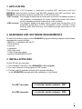
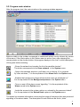
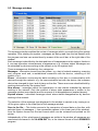
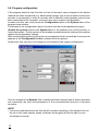
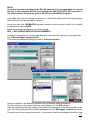
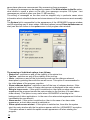
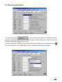
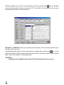
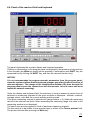
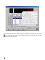
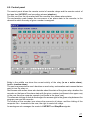
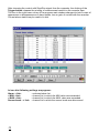
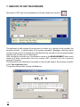
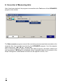
LEONARDO v.6.0 PROGRAM FOR WORK MANAGEMENT OF KR7 AND KE8 RECORDERS , USER S MANUAL 1 2 CONTENTS 1. APPLICATION .......................................................................................................... 5 2. HARDWARE AND SOFTWARE REQUIREMENTS ................................................. 5 3. INSTALATION DISC ................................................................................................. 5 4. PROGRAM INSTALLATION ..................................................................................... 6 5. SERVICE OF THE LEONARDO v.6.0. PROGRAM ................................................. 6 5.1. Program start ..................................................................................................... 6 5.2. Program main window ........................................................................................ 7 5.3. Message window ................................................................................................ 9 5.4. Background picture change - Background picture ............................................. 10 5.5. Entering and password change .......................................................................... 11 5.6. Program configuration ........................................................................................ 12 5.7. System calibration .............................................................................................. 15 5.8. Installation of tool programs ............................................................................... 16 5.9. Network scanning ............................................................................................... 17 6. SERVICE OF KE8 RECORDERS ............................................................................ 19 6.1. System parameters ............................................................................................ 21 6.2. Alarm parameters ............................................................................................... 22 6.3. Measuring parameters ....................................................................................... 23 6.4. Panel of the read-out field and keyboard ........................................................... 25 6.5. Control panel ...................................................................................................... 27 6.6. Recording paper ................................................................................................. 29 7. SERVICE OF KR7 RECORDERS ............................................................................ 30 8. CONVERTER OF MEASURING DATA .................................................................... 32 8.1. Service of the Data converter tool program .................................................... 33 9. SERIAL NUMBERS TOOL PROGRAM ................................................................ 36 3 4 1. APPLICATION The Leonardo v.6.0 program is destined to handle KR7 recorders with the MODBUS communication protocol and RS-485 interface and KE8 recorders with MODBUS communication protocol and RS-232 or RS-485 interface. KR7 recorder - the program enables the archiving and conversion of measuring data in the computer, visualisation of current measuring values and edition of text messages and their tranmission to the recorder. KR8 recorder - The program enables the work control, review and configuration of all accessible parameters in KE8, visualisation of the recorder current working state and archiving, and measuring data conversion in the computer. 2. HARDWARE AND SOFTWARE REQUIREMENTS To install the correct function of the LEONARDO program following hardware and software requirements must be fulfilled: - IBM-PC or compatible with the PC, - CD-ROM drive, - a mouse, - a keyboard, - VGA video card, - 10 Mb of free disc space, - windows 95/98/2000/NT4.0/XP. 3. INSTALLATION DISC On the CD disc are recorded: 1. The installation version of the LEONARDO v.6.0. program. 2. The users manual of the program in PDF format. 3. The key code (if ordered) unlocking the recorder handling in the LEONARDO program after the installation, in the format: For KR7 recorder: < recorder serial number>. KR7 For KE8 recorder: < recorder serial number>. KE8 5 4. PROGRAM INSTALLATION Start the Setup.exe installation file of the Leonardo program from the CD disc. Next, follow the instructions given on the screen. 5. SERVICE OF THE LEONARDO v.6.0. PROGRAM 5.1. Program start During the start, the LEONARDO program read out the current configuration from the LEONARDO.INI. file. If the configuration file has not been found or will include wrong data, the program accepts itself default settings and informs the user about it, displaying the message: After ending its operation the program saves the current operation on the disc, so the above message should not appear during the next start. Accepted by the system, default settings can be changed. 6 5.2. Program main window After the program start, the main window or the message window appears: Buttons visible in the toolbar correspond to commands which can be chosen by means of the menu. If the Hints option in the Option menu is active, then, after stopping the mouse pointer on the chosen button, the program displays in the hint a short description of the given button meaning: Scans the network and creates the list of accessible devices. The button corresponds to the Scan network in the System menu. Opens the message window or pull them out on the top, if it is covered by other windows . It is the equivalent of the Alarm list in the Option menu. Enables the background change which device icons are displayed on. It is the equivalent of the Background picture in the Option menu. Turns on and off the alarm sound signalling. It is the equivalent of the Alarm sound in the Option menu. Locks the access to the system options or unloads by the password check. It is the equivalent of the Unlock/Lock system in the System menu. The status line contains information concerning the usage of computer disc resources and signalling of the alarm states. The description of each field can be find in hints. 7 System load Fill up time Disc free space Disc space consumption per hour Percentage of occupied space The bulb turned on indicates a new event in the recorder, turned off, the normal work state of the system. Events which have appeared can be read out in the lamp hint, moreover they are notified in the message window together with the date and full description. A quick double click on the turned on lamp symbol means the information confirmation about a new alarm state and turns the lamp off. System load - indicates the system load by the measurement read-out from the network. When the load is extremely alarming, the status line changes its colour from green to red. This means, that too many devices are working in the network or they generate too many data that the system would be able to receive them. Fill up time possibility This field informs about the time estimated by the system after which the computer disc will be full of data (at current recorder parameter settings). Disc free space - This field informs about the current free space on the computer disc. Disc space consumption per hour This field informs about the on the computer disc per hour (in kb/h). Percentage of occupied space - 8 average space usage This field shows the proportion of the occupied space on the computer disc to its capacity and shows the value in percent. It allows to know quickly how much of free place is left on the disc and how quickly it decreases. 5.3 Message window The message window enables the review of messages which occurred during the system operation. After starting the system, messages are being read from the last session with the program and one can review them by means of the scroll bar, at the right side of the window. Each message is identified by the date and time of its appearance in the system, thanks to it, one can reproduce circumstances of appearance, e.g. of alarm states. Messages can be submitted by devices working in the network or by the system itself. These messages are divided into four categories: Messages - information issued from the system, e.g. start of network scanning, scanning end, program work end, re-established connection with the device, unlocking of the system, a.s.o. Errors - information concerning the data recording on the disc or communication with devices through the network, e.g. the communication lost with the device, the unknown device has changed its type, lack of place on the disc. These errors are submitted both by working devices and by the system itself. New alarms - messages about the appearance of new alarms submitted by devices working in the network. Only the moment of alarm state appearance is written in the message window (new alarms) and the moment of its disappearance (expired alarms). Expired alarms - submitted messages about alarm states disappearance by devices working in the network. The selection of the message type displayed in the window is carried on by turning on or off the given option in the lower part of the message window. Save to the file...- This button serves to the conversion of saved data on the disc, with selected types of messages ( from accessible options in the lower part of the window), from the system format into the text format which can be reviewed and printed on the printer. Independently of this, what types of messages are visible in the window, all messages are memorised and saved in the ALARM.DAT file, in the internal format of the LEONARDO program. 9 5.4. Change of the icon background picture - background picture It is possible to situate the background picture on which device icons will be displayed on the chosen place in the program window. Both the background and the icon position will be automatically memorised by the program. The background is selected in the Choose background picture....window. The system accept Bitmapa and Metafile picture formats. In the Lion/Leonard picture window one can review accessible background pictures without the necessity to close the main window of this option. In order to displace the icon on the background, click the selected icon with the mouse and holding the left key, pull it across on the new place, release the left key and the icon remains on the chosen place. 10 5.5. Entering and password change In order to obtain the access to the configuration options and to the system calibration dialogue, give the correct password. This locking allows to protect the system against any accidental change of its configuration by non-authorized people. The password also opens the access to some options in dialogues of particular device types. (e.g., search the opening password in recorders). To unlock the system, choose the Unlock the system...option in the System menu of the main program window or click the padlock icon on the tools bar . Write the correct password in the password window and press the Enter key on the computer keyboard or click the OK. key in the window. At the first start, the obligatory password is the word - LEONARDO, but one can change it into another one, then one must click the New password key. The program asks about the current password and if it is correctly given, then it will ask twice about the new password (to exclude the possibility of mistake). From this moment the new written password will be valid. After writing the correct password in, the padlock icon in the tool bar changes into an opened padlock and remains pressed until the moment of the system protection. To protect the system again, it is sufficient to click again on Lock the system option in the System menu window of the main program. The locking and unlocking of the system is written each time in the message file, in the form of a message submitted by the system (System word in the Type column). 11 5.6. Program configuration If the program starts for the first time or from its last start, some changes in the device network has been introduced (e.g. data transfer speed, type or port number to which the recorder is connected) or when a recorder with a different communication protocol has been connected to the computer, one must carry out a system reconfiguration. In order to do this, one must choose the Configuration option in the System menu of the program main window. The access to the configuration option is locked until the correct password is given (Unlock the system option in the System Menu or the padlock icon on the tool bar), to unlock the system. The lion picture in the window reminds about the locking of the system against the configuration change. After unlocking the system by giving the correct password, the Leonardo da Vincis portrait appears in the Configuration window, instead of the lion picture. At that time, one can carry out changes in the window of the system configuration. One can choose in the Network fold: number, baud rate and port type to which recorders are connected, the kind and parameters of the communication protocol of serviced recorders. NOTE: One must remember about the fact that all recorders operating in the network have to be set on the same transfer speed, otherwise the program will not be able to scan the network correctly. 12 NOTE: To control recorders working in the RS-485 network, it is recommended to connect the bus to the computer RS-322 port through the PD5 RS-232/RS-485 converter or any other similar (set the port type as RS-485 in LEONARDO program) In the disc fold, one can change the directory in which the system will save measurement data read out from the recorders network. At the first start, the LEONARDO program creates in the directory in which it is located, a subdirectory named DATA. Measurement data are saved in it in files named: DEV_< RECORDER IDENTIFICATION NUMBER>. In order to change the in-coming data directory one must click the key on the right side of the Measurement directory path. This opens an additional dialogue window, Choose directory: One can choose in the directory window only the already existing directory. The files existing in the chosen directory are displayed in the File window. After the measuring directory change, the path to the messages file is automatically changed - this is the path to the file in which messages from the Messages window are saved. This path cannot be changed manually - it is assumed, that the messages file will be in the 13 same place where are measurement files concerning these messages. The saving of messages can be stopped by means of the Write alarms to the file option, what allows to spare a place on the disc (one message occupies 128 bytes - two messages per minute it gives over than 11 MB monthly). The saving of messages on the disc must be stopped only in particular cases since information about submitted alarms and circumstances of their occurrence are irrevocably lost. The System fold is responsible for the appearance of the LEONARDO program window and the signalling way of alarm states. Individual options (except Show splashscreen at start) can also be chosen in the option menu in the program main window. The meaning of individual options is as follows: Status line - switches on and off the visibility of the status line. Tool bar - switches on and off the visibility of the tool bar. Hints - switches on and off the hint showing mode and the dialogue element description by pointing them with the mouse cursor. This option is recommended in the initial phase of the program cognition. Show unknown devices - switches on and off the icon of unknown devices. If this option is switched off, icons of foreign devices are not displayed in the main window. Bring to top on error - if this option is switched on, then after an alarm state appearance the program transfer the main window on the first plan (if it was hidden under others). This option is very useful when LEONARDO is working in the background of other applications - in the case of an alarm state appearance it informs immediately the user about it. Alarm sound - If this option is switched on, then in the case of an alarm state appearance, a short alarm sound is switched on. Show splash screen at start - If this option is switched on, then after the system start, the main window with the lion picture appears with the LEONARDO inscription. This option allows to switch the splash screen appearance off when starting the program. 14 5.7. System calibration In order to calibrate the system work, choose the System Calibration option in the System menu of the main program window. Calibration options will be blocked if we unlock the system by giving the password. The meaning of these particular options is as follows: Automatic dialogue refreshment - With each type of recorder, a dialogue window for reviewing and programming its internal registers can be assigned. This option allows switching on and off an automatic periodic refreshment of the contents of these dialogues, so it corresponds to the current state of registers. Additional device checking - The system refreshes information about the operation recorder working states as frequently as needed (usually no more frequently than the dot time). For a long dot time (e.g. every 40 sec), it may cause a too late reaction to alarm states appearance. If this option is switched on, the system performs in free time the additional checking of recorders to the early discovery of emergency states. That however increases the system load. Max. Number of accesses - This field defines how many recorders the system can service in one turn before it returns the control to the MS Windows program. At high system load it may happen that it will assign whole the time the communication with recorders operating in the network and stop to react to the keyboard and mouse. This option allows to define how often the system is to return the control to the MS Windows program, and this way speeds up the reaction to users command. Frequency of information refreshment (in sec) - This field defines in seconds how often information is to be refreshed in the status line concerning the computer disc consumption. 15 5.8. Installation of tool programs After installing the LEONARDO program, one must add to it, giving their own names, following tool program files: Data converter (Dviewer.exe) and Serial numbers (Num_ser.exe) from the LEONARDO program directory installed in the PC. Measuring data converter (Dviewer.exe) - The program converts stored data on the computer disc, from serviced recorders by the LEONARDO program, from the own format into *.dbf, *db, * csv and * txt. The service of the measuring data converter program has been described in the chapter 8. Serial numbers (Num_ser.exe) - The program reads out coded in the recorder memory: Device type, Identification number and Serial number. On the base of the recorder serial number, the file with the code key is generated. The service of the program to read-out the recorder serial number has been described in the chapter 9. To install these tool programs one must, after starting the Leonardo program, choose in the menu: Tools > Add or remove tools > Tool configuration > Add, find tool program files and add them successively to the main program. 16 5.9. Network scanning After configuring the system one must perform the network scanning. To do that, we choose the Network scanning option from the system menu of the program main window or we may click the magnifying glass icon on the tool bar. The scanning window appears. During the scanning, the program checks Identification numbers of recorders working in the network, trying to connect with them. The currently checked Identification number and a percentage of the entire scanning operation are displayed in the window. If the program connects to a device of given number, its type is being recognised. If the particular type is serviced by the program, then the icon of this device appears in its main window. At first connection of the LEONARDO program with the KR7 or KE8 recorder, the program reads out and saves on the computer disc the whole contents of the memory buffer of the given recorder (KR7 - max, up to 2 minutes of the recorder operation, KE8 - max. up to 30 hours of the recorder operation). Depending on the computer type and number of memorised data in the buffer of the given recorder, their read-out and saving on the computer disc can last up to ca 5 min. Meantime, in the program main window, the icon is displayed. After each renewed start of the LEONARDO program, it supplements data saved on the computer disc during the system operation and data memorised in the recorder memory buffer during the break of program operation are added. 17 In the KE8 recorder buffer data are only saved till the time of its filling (they are not superinscribed) and in the KR7 recorder, data in the buffer after its filling are superinscribed. If the scanned device is unknown for the program, the foreign device icon appears in the main window. If there is no file with code key of the given recorder in the program, the key symbol appears on its icon. - foreign device operating on MODBUS protocol, but not serviced by this version of program, - KR7 recorder, full access rights, - KR8 recorder, full access rights, Numbers under device icons in the program main window represent their Identification Numbers (network addresses) NOTICE: Recorders serviced by the Leonardo program must be assigned different Identification Numbers. During the system operation, icons representing particular recorders can change their appearance, signalling alarm states or disconnection from the recorders: - the recorder works normally, - in KE8/KR7 recorders the alarm state lasts (exclamation mark) - loss of connection with KE8/KR7 recorders (grey icon) After a double click on the device icon the relevant dialogue window is opened. Dialogue windows have different appearance and assignment depending on the type of device. E.g. for a foreign device it is an information window: 18 6. SERVICE OF KE8 RECORDERS KE8 type recorders are represented in the main window by means of icons e.g. After clicking the icon of the chosen recorder by means of the right mouse the handy menu is opened. After choosing the Parameters copying option, the dialogue window is opened enabling the copying of chosen parameter settings from the given recorder into other recorders of the same type , e.g.: 19 After choosing the parameters view, a dialogue window is opened, allowing programming recorder measuring channels (this window can also be opened through a quick double-clicking of the mouse left key). Meaning of particular folds in the window is as follows Read out - refreshes the contents of the visible side of the dialogue window by read-out of the measuring channel state from the device. Thanks to that, this side presents the current device state (Data in the column Current values), the key is useful at Automatic dialogues refreshment option switched off in the system calibration window (p.5.5.) Write write down to the device, new parameters values entered into selected edit fields. NOTICE: Parameters values entered as floating point numbers must be written in edit fields of the given channel, in the format currently displayed in program windows. 20 6.1. System parameters The access to the possibility of KE8 recorder parameter change is protected by means of the opening word, which is presented as a four digit number from the range 0000....9999 (see recorder users manual). Until we do not give the correct value of the opening word in the Password window and save it into the recorder (it unlocks the access to parameter change), the other parameters cannot be changed. If the system of the LEONARDO program is unlocked (p. 5.6.) then, after pressing the key, on the right side of the edit field, the option of the automatic read-out of the recorder Password is accessible. The program automatically finds the opening word, however it may even last up to 5 minutes, and with many recorders operating on the network, even longer. If the system has not been unlocked, the opening word must be entered each time while entering KE8 window. The programming of recorder system parameter consists of entering appropriate values into edit fields (New values column) and pressing Write key. 21 6.2. Alarm parameters While programming alarm parameters, as first the alarm parameter we want to program must be chosen. The program automatically copies current settings of this alarm to edit fields where they may be changed in any way. The program does not check whether set alarm parameters make sense - if they are inconsistent from recorder operation rules, the recorder will report the error while attempting to save. NOTE It may happen, that the recorder accepts entered alarm settings but they become valid only after the recorder ends persisting type description print out related to previous alarm settings. In such a case, in the right lower corner of the page relevant information appears explaining that entered settings do not apply yet. Alarm settings page serves also as information source - in the Relay column and in appropriate rows ALARM !!! messages appear, when the given relay is switched on (alarm state lasts). Messages will disappear when relevant alarm states cease in the recorder. 22 6.3. Measuring parameters The lightning symbol next to the representation of compensation kind informs, that at temperature measurements with a thermocouple the recorder tests the thermocouple break with a pulse current. In order to program the FPT conversion function (see recorder users manual) press the key at the right side of the FPT edition field. The additional edit window opens. 23 Particular options are chosen from dropdown lists, after pressing the key the window closes and selected function is inserted into FPT value field. The meaning of each option is explained by means of following hints: OU.UNIT and OBJECT fields may include special symbols of the recorder alphabet (see recorder users manual) A supporting table serves to their entry which is opened after clicking the key, at the right side of these fields. Clicking with the mouse on the selected symbol in the symbol table, enters the symbol into the target field. CAUTION! Opening of the alphabet table blocks FTP edit window and vice versa. 24 6.4. Panel of the read-out field and keyboard The panel duplicates the recorder display and keyboard operation. Clicking on relevant key in the program panel corresponds to the pressure of relevant key in the recorder (the Write key needs not be pressed). Combinations with SHIFT key are composed first by clicking the SHIFT key, and then the relevant function key). NOTICE! It is not recommended to program recorder parameters from the program panel, since the system realises about introduced changes only after the direct read-out of relevant registers. The change of the Identification Number (ID) done through the program panel causes the contact loss with the recorder. In such a case one must repeat the network scanning). Under the display and keyboard field, the summary of current measuring values from all switched on measuring channels of the given recorder is displayed - minimal, maximal, average values, units and the current recorder working mode. If the given measuring channel is switched off (range number = 0), fields with measuring values of this channel are blank. When exceeding the measuring range, the value in the measuring window is not displayed. The same rules are also applied in folds of particular measuring channel. The text which is to be written on the recorder tape, is written in the Text to printout field. The printout follows after pressing the Write key. 25 A supporting table serves to introduce special characters. It is opened by clicking the key. Clicking with the mouse on the selected character in the character table, on may introduce them to the text field. 26 6.5. Control panel The control panel allows the remote control of recorder relays and the remote control of the tape feed (INT/EXT) and recording release (stop/run). The first row from the top marked with the recorder icon shows alarm states. The exclamation mark means the occurrence of an alarm state in the recorder, in the channel to which the relay of given number is assigned. Bulbs in the middle row show the current activity of the relay (is on = active alarm), is off = inactive alarm). The next row presents the users decision on each relay: exclamation mark means that we want to turn the relay on. Red frames with arrows show who decides about the state of the given relay: whether the recorder on the base of the alarm state with the given number (red frame in the upper row) or the user from the computer console (red frame in the lower row). The alternate clicking of each bulb changes the access right to the given relay between the program user and the recorder. The clicking of the recorder icon returns the access to all relays, and the clicking of the computer icon - transmits to the user, the right to control all relays. An analogous rule manages the control of INT/EXT and Stop/Run signals. 27 After choosing the control with Stop/Run signal from the computer, the clicking of the Trigger button releases the printing of measurement results on the recorder tape. The icon in the right lower corner of the program main window changes its look in case of appearance or disappearance of alarm states, loss or gain of contact with the recorder. Current alarm states may be read in its hint. In icon hint following writings may appear: Alarm : <list> - activated alarm list < MIN: <list> - channel list, in which the MIN value was exceeded < MAX: <list> - channel list, in which the MAX value was exceeded Sensor break : < list> - channel list in which the sensor break was discovered 28 6.6. Recording paper tape The length of paper in the roll can be programmed in the Paper panel writing it in the New values window. During the program working, the current information about the number of working days for which there is enough of paper, is currently displayed. 29 7. SERVICE OF KR7 RECORDERS Recorders of KR7 type are represented in the main window by means of The switched on bulb signals the occurrence of events (e.g. alarms) in the recorder, the switched off bulb - a normal state of the system operation. Messages informing about events can be read out in the bulb hint, besides they are recorded in the message window together with the date and full description. After clicking the recorder icon, the window in which in the MEASUREMENT field current measuring data transmitted from the chosen KR7 recorder into the Leonardo program is opened. The information text destined to be printed on the recorder tape of this recorder is written in the Text to printout field. The printout follows after clicking the Print key. 30 To introduce characters in the Text to printout field, a supporting table serves, opened after clicking the key. Clicking with the mouse on the chosen character in the supporting table, this character is introduced to the text field. After occurring alarm events in the recorder, exceeding the measuring range or break of the measuring sensor, information about them is displayed in the MEASUREMENT field. The recorder icon is displayed with the symbol of event occurrence. NOTICE: 1. One cannot review and change KR7 recorder settings in the Leonardo ver.6.0 program. The KR7Setup program destined to this recorder parameter configuration is accessible. 31 8. Converter of Measuring data After it has been attached, the program is accessible in the Tool menu of the LEONARDO program main window. The Data converter program converts files containing measurement data recorded on the computer disc from recorders serviced by the LEONARDO program, from the program native format into *.dbf, *db, or * .cvs or *txt. Files in those formats are read by popular data base programs, calculation sheets and word processors. MS Excel is an example where converted data can be shown in the shape of diagrams, mathematical functions can be applied on them, a.s.o. 32 8.1. Servicing of the Data converter tool program In the displayed information program. By means of the Next key transit to the service of the information program in the displayed window information program. Settle the access path to data stored on the computer disc from recorders serviced by Leonardo program, the access path to the directory in which the data converted in the selected format will be recorded, the format of in-coming data and additionally for the CSV format one can set the decimal separator and the mark separating columns. 33 Choose the recorder type and its address in the network, and for KE8 recorder type settle the measuring channel number from which data are to be converted into the settled format above. Choose the time interval from which data are to be converted. 34 After accepting the settings, chosen measuring data are converted and saved in previously defined base: 35 9. SERIAL NUMBER TOOL PROGRAM The program is accessible in the Tool menu in the main window of the LEONARDO program. The Serial numbers program reads out coded device type, serial number and Identification number in the recorder memory. The Scan button starts the scanning procedure of recorders. Information about recorders operating in the system will appear one after another in the window, in the following format: Recorder type, Identification Number = Serial number The Stop button breaks the process of network scanning. 36 37 January 2004 38