1
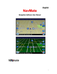
Installation Manual
Note: The URL on page two has changed to:
http://www.panavise.com
NavMate
Navigation System
2
Installation Manual
OVERVIEW
The NavMate® Navigation System consists of the following components:
MENU
Controller
GPS Antenna
Controller Bracket Assembly
Video Cable
ENTER
Display unit
Wire Harness
PLEASE VERIFY RECEIPT OF ALL COMPONENTS PRIOR TO ATTEMPTING TO INSTALL THE SYSTEM
INTO A VEHICLE.
COMPONENT
1) Controller
2) Controller
brackets
3) Display unit
4) Display bracket*
5) GPS antenna
6) Video cable
7) Wire harness
8)CD-ROM**
LOCATION/FUNCTION
PART NUMBER
Mounts under a seat or in the trunk
XU3F-18K931-AA
Mounts the controller to the vehicle
Mounts to the instrument panel
Mounts the display unit to the instrument panel
Mounts on top of the instrument panel or package shelf
Connects the controller and display unit
Connects the controller to the necessary vehicle signals
Contains the navigation software and map database
XU3F-19A028-BA
XU3F-10E889-AA
NA
XU3F-14B286-AA
XU3F-18B921-MA
XU3F-18B921-NA
various
*Not included with kit. Vehicle-specific InDash brackets and an adapter for the NavMate display unit may
be ordered from Panavise. Refer to www.panavise.com/comm/indash/idbrand.html for details.
**Not included with kit. The CD-ROM for the appropriate geographic region must be ordered from
Navigation Technologies. Please call 1-888-NavMaps (628-6277) for questions or more information.
NavMate® Navigation System
Installation Manual
3
CAUTIONS
Before installing the system, please read the following cautions. Failure to do so may result in
damage to the system:
Controller
1) Do not interrupt power to the system while the software is updating. This may result in
corruption of the controller memory.
2) Never drop the controller. This may destroy the gyroscope or other components.
3)The controller MUST be mounted horizontally. Use a bubble level and a protractor to
ensure the controller does not exceed 5 degrees from horizontal level.
4) Mount the controller securely to ensure proper gyroscope function.
5) Mount the controller away from other electronics which may interfere with the GPS receiver.
6) Mount the controller away from strong magnetic fields.
Display unit
1) Never drop the display unit.
2) Do not apply pressure to the display screen.
3) Clean the display unit with a soft cotton cloth (or lens tissue) dampened with 70%
isopropyl alcohol (rubbing alcohol). Any other cleaning fluids may damage the LCD screen.
C d - r om
1) Never drop the CD-ROM.
2) Never subject the CD-ROM to a magnetic field.
3) Use standard CD-ROM cleaning procedures.
GPS antenna
1) Mount the GPS antenna in a position that provides good satellite visibility.
2) Mount the GPS antenna away from other electronics which may interfere with antenna
reception.
3) Do not cut, pinch or sharply bend the GPS antenna cable.
Wire harness
1) Never connect to any safety system circuits (air bag, seat belt etc.).
2) Disconnect the battery cable prior to making any connections.
NavMate® Navigation System
Installation Manual
4
INSTALLATION
Determine system layout
1) Determine the location to connect to the vehicle speed signal.
2) Determine the location to connect to the remaining vehicle signals required by NavMate. See chart
on Pg. 5 for signal requirements and NavMate wire colors.
3) Determine general component layout, e.g., where the controller will be mounted.
Connect wires and route cables
1) Connect wire harness to vehicle using splice(piggyback)method. Using a multimeter, verify the battery,
ignition, ground, and backup connections.
The NavMate system wire harness has five wires which must be connected to the vehicle. See chart on Pg. 5
for requirements.
Ground (black):: Connect to a vehicle ground. Maintain the shortest ground loop possible by connecting
directly to a body ground point if available.
Ignition (pink):: Connect to a circuit which is powered only with the key on/run. An example is the turn
signal circuit.
Battery (red):: Connect to a circuit which is powered constantly. An example is the hazard signal circuit.
Reverse (light green):: Connect to a circuit which is powered only when the vehicle is in reverse. An example
is the backup light.
Speed signal (green/white OR yellow):: The vehicle must have a vehicle speed signal (VSS) output in the
form of a square wave or a sine wave. Use the green/white or the yellow wire, depending on VSS type. (See
chart on Pg. 5.) Connect to a circuit which carries the signal that drives the odometer.
Special attention must be given to the vehicle speed sensor (VSS) connection. For vehicles with a digital
signal (square wave, TTL) connecting to the green/white striped wire will provide a proper signal.
In some vehicles (e.g., certain Ford/Lincoln/Mercury ), the vehicle speed signal comes from a variable
reluctance sensor which has a sine wave output. Connecting to the yellow wire will provide a proper signal.
Some vehicles do not have a speed signal that is available to NavMate (e.g., most vehicles built before 1982,
and vehicles with speed signal carried on a bus).
NavMate® Navigation System
5
Installation Manual
Connect wires and route cables (cont’d.)
Signal
Battery
Ignition
Ground
VSS
Backup
NavMate wire
Requirements
Red
Pink
Low level voltage VL max
High level voltage VH min
Black
Grn/Wht (square wave)
Input pulse frequency
Input voltage range
Low level voltage VL max
High level voltage VH min
Yellow (sine wave)
Input pulse frequency
Input voltage range
Lt. Green
Low level voltage VL max
High level voltage VH min
8
Typical location
Fuse block
Fuse block
+13.8 V DC nominal, 3 Amp (min)
+13.8V DC nominal (when ignition on)
1.0 VL (max)
7.0 VH (min)
battery minus
square wave
˜0Hz to 2.5 kHz
-13 to +26 Vmax
0.9 VL (max)
4.0 VH (min)
sine wave
1 Hz to 200 Hz
-13 to +26 Vmax
+13.8V DC nominal (when vehicle in reverse)
1.0 VL (max)
7.0 VH (min)
7
6
5
4
3
Chassis
PCM
Backup light
2
1
16
9
10
11
12
13
14
15
CONTROLLER CONNECTOR
(WIRE HARNESS VIEW)
Number
1
2
3
4
Circuit
–
–
–
–
5
–
6
7
8
–
–
–
Circuit Function
Number
Ground (battery minus)
9
Reverse gear signal
10
Ignition signal
11
Vehicle speed signal
12
(sine wave)
13
Vehicle speed signal
14
(square wave)
15
Not used
16
Not used
Not used
Circuit
–
–
–
–
–
–
–
–
Circuit Function
Not used
Not used
Not used
Not used
Not used
Not used
Not used
System power source
(battery plus)
NavMate® Navigation System
Installation Manual
6
2) Route the video cable between the controller mounting location and the display mounting location.
NOTE:
Right angle connector mates to the controller.
Verify system starts and update software
1) Make sure ignition is OFF.
2) Connect wire harness to controller and video cable to controller and display unit.
3) Turn on ignition.
4) Install the CD-ROM into the controller. NavMate will update its software. DO NOT TURN OFF THE
IGNITION WHILE NAVMATE IS UPDATING.
5) Verify that NavMate powers-up correctly.
Mount components and tuck cables
1) Controller mounting
Mount the controller to the vehicle using the brackets provided. The controller must be firmly attached
to the vehicle for the system to function properly. Do not overtighten. Do not mount the controller
upside down. The controller must be mounted level to within 5 degrees. Use a bubble level and a
protractor to verify. Follow the rules under the CAUTIONS section on Pg 3.
Using a utility knife, slit the carpeting as necessary. Use double-sided tape to secure the brackets
underneath the carpet. The two L-shaped mounting brackets may be reversed for mounting to the floor.
NOTE: Upon removal of the controller, reverse procedure and seal carpet slit with double-sided
tape.
2) GPS antenna mounting
The GPS antenna must be mounted in a place that provides good satellite visibility. If a clear view
cannot be obtained inside the vehicle due to a vertical windshield (e.g., some delivery trucks), the
antenna may be mounted outside the vehicle. Using double-sided tape, mount the GPS antenna to the
instrument panel or package shelf. Plug the antenna cable into the controller.
3) Display Unit Mounting
Mount the display unit using the vehicle-specific bracket or flex mount. Do not overtighten. See
www.panavise.com/comm/indash for details.
4) Tuck all cables into the vehicle sill. Make sure the cables are not pinched or sharply bent.
Setup, Initialize, and Calibrate
GPS initialization allows the GPS receiver to find its current location. The GPS must be initialized every time
battery power is disconnected. This process is quickened by using the system diagnostic menu.
1) Move the vehicle outside to an area where the GPS antenna will have a clear view of the sky.
2) Power-up the system. From the “Please drive safely” screen, activate the diagnostic mode by
pressing the following controls: UP ARROW, UP ARROW, RIGHT ARROW, MENU. This must be done
“smoothly”. You will receive a notice that diagnostics are now activated under the Options Menu.
NavMate® Navigation System
Installation Manual
3)
4)
5)
6)
7)
8)
7
Press ENTER to advance to the Main Menu. Press the OPT (Options) soft key.
Select Preferences and set the Volume to level 4. Press ENTER.
Select System Diagnostics from the Options Menu.
Select GPS.
Select GPS Initialization.
Select “Yes” to confirm.
The GPS should initialize in 7-15 minutes. You do not need to be present during this time. Take this
opportunity to fill out the warranty registration for the system, and place the User Manual and
CD-ROM case in the vehicle glove compartment. After initialization is complete, the system will beep and
return to the Diagnostic Menu.
9) Drive the vehicle approximately 10-15 miles to allow the system to find its current location and calibrate
for the speed signal pulse rate and the gyroscope. Verify the VSS connection. (Make sure that the
vehicle icon is moving.)
10) After a few miles of driving, verify that the vehicle icon position is close to the actual vehicle position.
Make several turns and verify that the system recognizes them.
11) The system may now be returned to the customer. Inform the customer that you have “rough calibrated”
the system and that over the next 30 miles of driving the system will “fine calibrate” itself.
NavMate® Navigation System