1
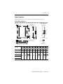
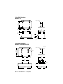
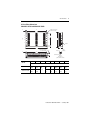
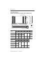
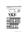
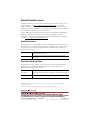
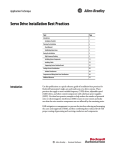
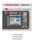
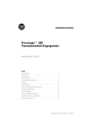
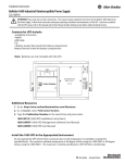
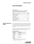
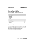
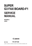
Installation Instructions
AC Line Filters
Description
Single-phase
(250...300V ac)
Cat. No.
Cat. No.
Cat. No.
2090-UXLF-106
2090-UXLF-HV323
2090-XXLF-TC316
2090-UXLF-110
2090-UXLF-HV330
2090-XXLF-TC350
2090-UXLF-123
2090-UXLF-HV350
2090-XXLF-TC365
2090-UXLF-132
2090-XXLF-X330B
2090-XXLF-TC3100
2090-XXLF-375
2090-XXLF-TC3150
2090-XXLF-375B
2090-XXLF-TC3200
2090-XXLF-3100
2090-XXLF-TC3250
2090-UXLF-136
2090-XXLF-TC116
Three-phase
(250V ac)
Description
Three-phase
(500...520V ac)
2090-UXLF-336
2090-UXLF-350
About This Publication
This publication contains installation instructions for ac line filters used with
Rockwell Automation servo drive systems. Included are mounting and wiring
instructions, and mounting dimensions.
For product specifications, refer to the Kinetix Motion Control Selection Guide,
publication GMC-SG001.
Publication 2090-IN013B-EN-P — January 2007
2
AC Line Filters
Important User Information
Solid state equipment has operational characteristics differing from those of electromechanical equipment.
Safety Guidelines for the Application, Installation and Maintenance of Solid State Controls (publication
SGI-1.1 available from your local Rockwell Automation sales office or online at
http://literature.rockwellautomation.com) describes some important differences between solid state
equipment and hard-wired electromechanical devices. Because of this difference, and also because of the
wide variety of uses for solid state equipment, all persons responsible for applying this equipment must
satisfy themselves that each intended application of this equipment is acceptable.
In no event will Rockwell Automation, Inc. be responsible or liable for indirect or consequential damages
resulting from the use or application of this equipment.
The examples and diagrams in this manual are included solely for illustrative purposes. Because of the many
variables and requirements associated with any particular installation, Rockwell Automation, Inc. cannot
assume responsibility or liability for actual use based on the examples and diagrams.
No patent liability is assumed by Rockwell Automation, Inc. with respect to use of information, circuits,
equipment, or software described in this manual.
Reproduction of the contents of this manual, in whole or in part, without written permission of Rockwell
Automation, Inc., is prohibited.
Throughout this manual, when necessary, we use notes to make you aware of safety considerations.
WARNING
IMPORTANT
ATTENTION
Identifies information about practices or circumstances that can cause an explosion in
a hazardous environment, which may lead to personal injury or death, property
damage, or economic loss.
Identifies information that is critical for successful application and understanding of
the product.
Identifies information about practices or circumstances that can lead to personal injury
or death, property damage, or economic loss. Attentions help you to identify a hazard,
avoid a hazard, and recognize the consequences.
SHOCK HAZARD
Labels may be on or inside the equipment, for example, a drive or motor, to alert
people that dangerous voltage may be present.
BURN HAZARD
Labels may be on or inside the equipment, for example, a drive or motor, to alert
people that surfaces may reach dangerous temperatures.
Publication 2090-IN013B-EN-P — January 2007
AC Line Filters
3
Before You Begin
For general guidelines when laying out your panel and mounting your ac line filter,
refer to the System Design for Control of Electrical Noise Reference Manual,
publication GMC-RM001. For guidelines specific to your application, refer to
Additional Resources on page 11 for the user manual available for your servo drive.
ATTENTION
To avoid personal injury or damage to equipment due to hazardous voltages,
follow these guidelines when installing your ac line filter. NEC and local
regulations always take precedence.
• Disconnect mains power prior to installation.
• Verify that the rated voltage is compatible with the local supply voltage.
• Connect the earth ground connection first when making connections.
IMPORTANT
Remove corrosion, oil, or grease from bus bar mountings by scrubbing surfaces
with a dry scrubbing pad. Do not touch cleaned surfaces with bare hands to
prevent further contamination.
TIP
The Bulletin 2094 mounting brackets, catalog number 2094-XNBRKT-1, are
designed to save panel space by letting you mount the Kinetix 6000 power rail
or line interface module (LIM) over the ac line filter.
Refer to the 2094 Mounting Brackets Installation Instructions, publication
2094-IN008, for more information.
Publication 2090-IN013B-EN-P — January 2007
4
AC Line Filters
Installing the AC Line Filter
Follow these steps to install your ac line filter.
1. Determine the location for your ac line filter on the panel.
Refer to Additional Resources on page 11 for the user manual with specific
information regarding your servo-drive system layout. Position the ac line
filter as close to the drive as possible.
2. Mount the ac line filter on the panel.
Refer to Product Dimensions on page 5 for mounting dimensions. Use
proper high-frequency (HF) bonding techniques to improve overall system
performance.
3. Connect the ac line filter as shown in these examples.
Bonded Cabinet
Ground Bar
Ground Terminals (1)
L3
L2
Line, AC Mains
Input Fusing
Three-phase
AC Line Filter
L3’
L3
L2’
L2
L1
L1
L1’
Line
Load
L3
L3’
Three-phase
L1 AC Line Filter
L2’
Servo Drive
Input Power
Connections
Bonded Cabinet
Ground Bar
Ground Terminal (1)
L2
Line, AC Mains
Input Fusing
(1)
Line
L1’
L3
L2
Servo Drive
Input Power
Connections
L1
Load
Ground terminal designators could also be PE/PE’ or E/E’.
These examples show a three-phase ac line filter. Single-phase ac line filter
installation is similar. For additional wiring information, refer to the
appropriate user manual for interconnect diagrams specific to your servo
drive application.
Publication 2090-IN013B-EN-P — January 2007
AC Line Filters
5
Product Dimensions
Mounting dimensions for ac line filters are given on the following pages.
AC Line Filter Dimensions
2090-UXLF-106, 2090-UXLF-110, 2090-UXLF-123, 2090-UXLF-132, 2090-UXLF-HV323
Dimensions are in mm (in.)
Ø 5 (0.20)
M4 (4) studs required
for back mounting.
A
B
2090-UXLF-132
Terminal Configuration
25
(1.0)
Line
C Load
I
25
(1.0)
D
E
J
Nut (2)
F
Ø 7 (0.27)
M6 (2) studs required
for side mounting.
H
G
PCB Board
Plain Washer (2)
Detail A
M5 Stud Set
(earth terminals are M5)
A
B
C
D
E
F
9.0
(0.35)
152.0
(5.99)
55.0
(2.17)
18.0
(0.71)
170.0
(6.69)
G
H
I
J
10.0
(0.39)
152.0
(5.99)
92.0
(3.62)
25.0
(0.98)
145.0
(5.71)
40.0
(1.58)
204
(8.04)
47.0
(1.85)
Cat. No.
mm (in.)
2090-UXLF-106
104.0
(4.0)
2090-UXLF-110
2090-UXLF-123
2090-UXLF-132
9.0
(0.35)
11.0
(0.43)
192.0
(7.56)
164.0
(6.46)
16.0
(0.63)
20.0
(0.79)
214.0
(8.42)
11.0
(0.43)
19.0
(0.75)
192.0
(7.56)
2090-UXLF-HV323
Publication 2090-IN013B-EN-P — January 2007
6
AC Line Filters
AC Line Filter Dimensions
2090-UXLF-136
Ø = 12 (0.47)
Radius = 3.0 (0.12)
Detail A
101
(3.98)
Line
Load
12
(0.47)
Dimensions are in mm (in.)
20
(0.79)
22
(0.87)
80
(3.15)
Detail A
104
(4.10)
M6
86
(3.39)
60
(2.36)
M6 x 12
55
(2.17)
174
(6.8)
120
(4.7)
20
(0.79)
AC Line Filter Dimensions
2090-UXLF-336 and 2090-UXLF-350
Ø = 12 (0.47)
Radius = 3.0 (0.12)
128
(5.0)
Line
L1
L1'
L2
L2'
L3
L3'
Detail A
Load
M6
12
(0.47)
E
Dimensions are in mm (in.)
120
(4.7)
113
(4.4)
Detail A
25
25 (0.9) 25
(0.9)
(0.9)
110
(4.3)
22
(0.9)
55
(2.2)
230
(9.0)
Publication 2090-IN013B-EN-P — January 2007
147
(5.8)
AC Line Filters
7
AC Line Filters Dimensions
2090-UXLF-HV330 and 2090-XXLF-X330B
M5 (4) studs required
for back mounting.
B
L3'
L2
L2'
L1
L1'
E
E'
Line
L3
D
G
Load
A
Detail A
E
C
H
M8 (2) studs required
for side mounting.
A
Nylon
Bushing
Nut (2)
B
F
Plain Washer (2)
Detail A
M5 Stud Set
(earth terminals are M5)
A
B
C
D
E
F
G
H
Cat. No.
mm (in.)
2090-UXLF-HV330
2090-XXLF-X330B
11.0
(0.4)
338
(13.3)
15.0
(0.6)
330
(13.0)
360
(14.2)
145
(5.7)
29.5
(1.1)
16.0
(0.63)
204
(8.0)
40.0
(1.6)
155
(6.1)
20.0
(0.8)
32.5
(1.3)
195
(7.7)
65.0
(2.5)
Publication 2090-IN013B-EN-P — January 2007
8
AC Line Filters
AC Line Filter Dimensions
2090-UXLF-HV350, 2090-XXLF-375, 2090-XXLF-375B, and 2090-XXLF-3100
M5 (4) studs required for
back mounting (dual keyway).
Detail A
L3'
L2
L2'
Load
Line
L3
F
C
L1
L1'
E
E'
D
A
E
Nylon
Bushing
B
H
G
Nut (2)
Washer (3)
I
M6 (4) studs required
for side mounting.
A
B
C
D
J
Detail A
M6 Stud Set
(earth terminals are M8)
K
E
F
Cat. No.
mm (in.)
578
(22.7)
618
(24.3)
160
(6.3)
2090-XXLF-375
2090-XXLF-375B
646
(25.4)
686
(27.0)
192
(7.5)
2090-XXLF-3100
741
(29.2)
785
(30.9)
G
H
2090-UXLF-HV350
35
(1.4)
20
(0.8)
215
(8.4)
30
(1.2)
21.5
(0.85)
I
J
K
35
(1.4)
70
(2.7)
20
(0.8)
47
(1.8)
80
(3.1)
18
(0.7)
Cat. No.
mm (in.)
2090-UXLF-HV350
578
(22.7)
2090-XXLF-375
2090-XXLF-375B
646
(25.4)
2090-XXLF-3100
741
(29.2)
15
(0.6)
Publication 2090-IN013B-EN-P — January 2007
230
(9.0)
262
(10.3)
275
(10.8)
AC Line Filters
9
AC Line Filter Dimensions
2090-XXLF-TC316, 2090-XXLF-TC350, 2090-XXLF-TC365, and 2090-XXLF-TC3100
F
G
G
C
H
K
I
J
TYP
AA
D B
E
A
A
B
230
(9.0)
50
(1.96)
180
(7.08)
85
(3.35)
240
(9.45)
95
(3.74)
G
H
C
D
E
F
25
(0.98)
215
(8.46)
200
(7.87)
65
(2.56)
164
(6.45)
150
(5.90)
90
(3.54)
75
(2.95)
223
(8.78)
210
(8.27)
I
J
K
Cat. No.
mm (in.)
2090-XXLF-TC316
2090-XXLF-TC350
2090-XXLF-TC365
2090-XXLF-TC3100
80
(3.15)
Cat. No.
mm (in.)
2090-XXLF-TC316
2090-XXLF-TC350
2090-XXLF-TC365
2090-XXLF-TC3100
12
(0.47)
M6x25
1.0
(0.04)
5.5
(0.21)
15
(0.59)
M8x40
1.5
(0.06)
5.5
(0.21)
16
(0.63)
39
(1.53)
43
(1.69)
Publication 2090-IN013B-EN-P — January 2007
10
AC Line Filters
AC Line Filter Dimensions
2090-XXLF-TC3150, 2090-XXLF-TC3200, and 2090-XXLF-TC3250
330
(12.9)
310
(12.2)
Dimensions are in mm (in.)
250
(9.8)
37 (1.4)
90
(3.54)
96
(3.8)
200
(7.8)
37 (1.4)
2x 285
(11.2)
43.5 (1.7)
Ø 4x 11
(0.43)
52 (2.0)
2x 165
(6.5)
52 (2.0)
M10 x 30
Recommended Torque for
Bus Bar = 24 Nm (212 lb-in)
43.5 (1.7)
310
(12.2)
AC Line Filter Dimensions
2090-XXLF-TC116
12
(0.47)
Dimensions are in mm (in.)
200
(7.87)
12
(0.47)
M6x25
80
(3.15)
1.0
(0.04)
15
(0.59)
L1'
215
(8.46)
230
(9.0)
Publication 2090-IN013B-EN-P — January 2007
PE
Load
N
L1
PE
Line
TYP
N'
5.5
(0.21)
25
(0.98)
50
(1.96)
AC Line Filters
11
Additional Resources
The following documents contain additional information concerning related
Allen-Bradley products.
Resource
Description
Kinetix 2000 Multi-axis Servo Drive User Manual,
publication 2093-UM001
Kinetix 6000 Multi-axis Servo Drive User Manual,
publication 2094-UM001
Kinetix 7000 High Power Servo Drive User Manual,
publication 2099-UM001
Ultra3000 Digital Servo Drive Installation Manual,
publication 2098-IN003
Information on system layout, including the ac line
filter for your Kinetix motion control servo drive.
Ultra5000 Intelligent Positioning Drive Installation
Manual, publication 2098-IN001
Ultra1500 Digital Servo Amplifier User Manual,
publication 2092-UM001
Kinetix Motion Control Selection Guide,
publication GMC-SG001
System Design for Control of Electrical Noise
Reference Manual, publication GMC-RM001
Kinetix motion control drive/motor specifications,
combinations, and accessories including ac line
filters.
Information, examples, and techniques designed to
minimize system failures caused by electrical noise.
EMC Noise Management DVD, GMC-SP004
Rockwell Automation Configuration and Selection
Tools, website http://ab.com/e-tools
Online product selection and system configuration
tools, including AutoCAD (DXF) drawings.
Rockwell Automation Product Certification, website
http://rockwellautomation.com/products/certification
For declarations of conformity (DoC) currently
available from Rockwell Automation.
National Electrical Code, Published by the National
Fire Protection Association of Boston, MA.
An article on wire sizes and types for grounding
electrical equipment.
You can view or download publications at
http://literature.rockwellautomation.com. To order paper copies of technical
documentation, contact your local Rockwell Automation distributor or sales
representative.
Publication 2090-IN013B-EN-P — January 2007
Rockwell Automation Support
Rockwell Automation provides technical information on the Web to assist you in
using its products. At http://support.rockwellautomation.com, you can find
technical manuals, a knowledge base of FAQs, technical and application notes,
sample code and links to software service packs, and a MySupport feature that you
can customize to make the best use of these tools.
For an additional level of technical phone support for installation, configuration,
and troubleshooting, we offer TechConnect Support programs. For more
information, contact your local distributor or Rockwell Automation representative,
or visit http://support.rockwellautomation.com.
Installation Assistance
If you experience a problem with a hardware module within the first 24 hours of
installation, please review the information that's contained in this manual. You can
also contact a special Customer Support number for initial help in getting your
module up and running.
United States
1.440.646.3223
Monday – Friday, 8am – 5pm EST
Outside United States
Please contact your local Rockwell Automation representative for any technical
support issues.
New Product Satisfaction Return
Rockwell tests all of its products to ensure that they are fully operational when
shipped from the manufacturing facility. However, if your product is not
functioning, it may need to be returned.
United States
Contact your distributor. You must provide a Customer Support case number (see
phone number above to obtain one) to your distributor in order to complete the return
process.
Outside United States
Please contact your local Rockwell Automation representative for return procedure.
Allen-Bradley, Kinetix, Rockwell Automation, TechConnect, Ultra1500, Ultra3000, and Ultra5000 are trademarks of
Rockwell Automation, Inc.
Trademarks not belonging to Rockwell Automation are property of their respective companies.
Publication 2090-IN013B-EN-P — January 2007
Supersedes Publication 2090-IN013A-EN-P — August 2006
PN 334021-P02
Copyright © 2007 Rockwell Automation, Inc. All rights reserved. Printed in the U.S.A.