1
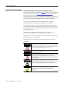
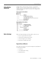
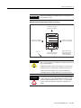
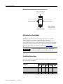
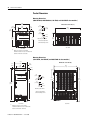
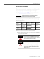
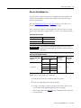
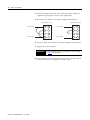
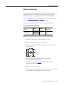
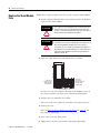
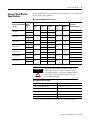
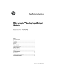
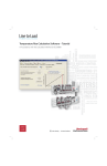
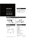
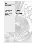
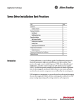
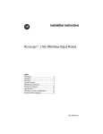
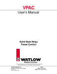
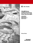
Installation Instructions
External Shunt Modules
Catalog Numbers
1394-SR9A, 1394-SR9AF, 1394-SR36A, 1394-SR36AF,
2090-SR120-09, 2090-SR040-09, 2090-SR040-18
About the External Shunt
Modules
Topic
Page
About the External Shunt Modules
1
Important User Information
2
Catalog Number Explanation
3
Before You Begin
3
Install the External Shunt Module
13
Replace the Shunt Module Fuse
20
External Shunt Module Specifications
21
Additional Resources
22
These externally-mounted passive shunt modules provide a means for
servo drives to dissipate excess regenerative energy from the DC bus.
This is needed when system loads require power dissipation beyond
the capability of the shunt resistor internal to the servo drive. These
are passive shunt resistors and require transistor activation by the
servo drive.
A properly-sized shunt module regulates excessive bus voltage by
passing current through a resistor, which dissipates the current as heat
and minimizes drive faults caused by excess bus voltage.
Shunt Module Compatibility
Shunt Cat. No.
Drive Cat. No.
2090-SR120-09
2098-xxx-HV030 and 2098-xxx-HV050
2090-SR040-09
2098-xxx-HV100
2090-SR040-18
2098-xxx-HV100
1394-SR9A
1394-SR9AF
1394-SR36A
2094-BSP2 (1) and
1394x-SJT22-x
1394-SR36AF
(1)
The 2094-BSP2 shunt module is mounted on the Bulletin 2094 power rail and
provides connections to an external shunt module.
2
External Shunt Modules
Important User Information
Solid state equipment has operational characteristics differing from those of
electromechanical equipment. Safety Guidelines for the Application, Installation and
Maintenance of Solid State Controls (publication SGI-1.1 available from your local Rockwell
Automation sales office or online at http://literature.rockwellautomation.com) describes
some important differences between solid state equipment and hard-wired
electromechanical devices. Because of this difference, and also because of the wide variety
of uses for solid state equipment, all persons responsible for applying this equipment must
satisfy themselves that each intended application of this equipment is acceptable.
In no event will Rockwell Automation, Inc. be responsible or liable for indirect or
consequential damages resulting from the use or application of this equipment.
The examples and diagrams in this manual are included solely for illustrative purposes.
Because of the many variables and requirements associated with any particular installation,
Rockwell Automation, Inc. cannot assume responsibility or liability for actual use based on
the examples and diagrams.
No patent liability is assumed by Rockwell Automation, Inc. with respect to use of
information, circuits, equipment, or software described in this manual.
Reproduction of the contents of this manual, in whole or in part, without written permission
of Rockwell Automation, Inc., is prohibited.
Throughout this manual, when necessary, we use notes to make you aware of safety
considerations.
WARNING
IMPORTANT
ATTENTION
Identifies information about practices or circumstances that can cause
an explosion in a hazardous environment, which may lead to personal
injury or death, property damage, or economic loss.
Identifies information that is critical for successful application and
understanding of the product.
Identifies information about practices or circumstances that can lead
to personal injury or death, property damage, or economic loss.
Attentions help you to identify a hazard, avoid a hazard, and recognize
the consequences.
SHOCK HAZARD
Labels may be on or inside the equipment, for example, a drive or
motor, to alert people that dangerous voltage may be present.
BURN HAZARD
Publication 2090-IN004B-EN-P — June 2008
Labels may be on or inside the equipment, for example, a drive or
motor, to alert people that surfaces may reach dangerous
temperatures.
External Shunt Modules
Catalog Number
Explanation
3
Catalog numbers consist of various characters, each of which
identifies a specific version or option for that component. Use the
catalog numbering charts below to understand the configuration of
your shunt module.
Bulletin 1394 External Shunt Modules
1394 - SR xxxx
kW Rating
9A = 300 W continuous, 4 Ω , no fan
9AF = 900 W continuous, 4 Ω , no fan
36A = 1800 W continuous, 4 Ω , no fan
36AF = 3600 W continuous, 4 Ω , fan-cooled, thermal switch
SR = Shunt Resistor
Bulletin Number
Bulletin 2090 External Shunt Modules
2090 - SR xxx - xx
Continuous Power Rating
09 = 900 W continuous, no fan
18 = 1800 W continuous, no fan
Resistance Rating
120 = 120 Ω
040 = 40 Ω
SR = Shunt Resistor
Bulletin Number
Before You Begin
Before you begin mounting your shunt module, make sure you:
•
have the required tools and materials.
•
understand the mounting requirements.
•
understand high-frequency bonding.
•
know how to establish noise zones.
Required Tools and Materials
These tools and materials are required to complete the installation of
an external shunt module:
•
Screwdrivers
•
User-supplied power wiring
•
Mounting fasteners
Publication 2090-IN004B-EN-P — June 2008
4
External Shunt Modules
Mounting Requirements
ATTENTION
Plan the installation of your system so that you can perform all cutting,
drilling, tapping, and welding with the system removed from the
enclosure. Because the system is of the open type construction, be
careful to keep any metal debris from falling into it. Metal debris or
other foreign matter can become lodged in the circuitry, which can
result in damage to components.
These requirements apply when preparing to mount your shunt
module:
•
Mount the shunt in an enclosure providing protection against
dust and splashing water (IP54), or dust free and protected
against water jets (IP65).
Many NEMA (National Electrical Manufacturers Association)
Type 4 cabinets provide this level of protection.
•
Install the panel for mounting your system components inside
the enclosure on a flat, rigid, vertical surface that won’t be
subjected to shock, vibration, moisture, oil mist, dust, or
corrosive vapors.
Refer to Environmental Specifications on page 21 for specific
recommendations.
•
Maintain minimum clearances for proper airflow, easy module
access, and proper bend radius for the cables as shown in the
figures beginning on page 5.
•
Use high-frequency (HF) bonding techniques to connect the
module, enclosure, machine frame, and motor housing, and to
provide a low-impedance return path for high-frequency (HF)
energy and reduce electrical noise.
Refer to HF Bonding Your Shunt Module, on page 6, for more
information.
•
Segregate DC-bus wiring from control wiring and motor
feedback cables. Do not run shunt wiring in wireways. Use
twisted pair cable from the drive to external shunt module.
Refer to Establishing Noise Zones, beginning on page 6, for
specific recommendations.
Publication 2090-IN004B-EN-P — June 2008
External Shunt Modules
IMPORTANT
5
Mount the shunt module in an upright position. Do not mount the
shunt module on its side.
Minimum Clearance Requirements (within an enclosure)
150 mm (6.0 in.) clearance
for airflow and installation.
150 mm (6.0 in.) clearance
for airflow and installation.
150 mm (6.0 in.) clearance
for airflow and installation.
Shunt Module
ALLEN-BRADLEY
R
BULLETIN 1394 300W SHUNT MODULE
CAT.
PART
SER.
INPUT DC
INPUT AC
FOR FUSE REPLACEMENT USE:
BUSSMAN CAT. NO.
FOR USE WITH 1394-SJT22-X SYSTEM MODULE
Enclosure
BURN HAZARD
150 mm (6.0 in.) clearance
for airflow and installation.
Bulletin 1394 and 2090
External Shunt Modules
(1394-SR9Ax module is
shown in this example.)
The shunt resistors can reach temperatures in excess of 350 ° C
(662 ° F). Do not handle a shunt module that has been operational until
it has cooled sufficiently.
Combustible materials above the shunt module or its enclosure may
need the protection of a metal plate to shield them from the heat.
Failure to observe these precautions could result in damage to
surrounding materials, possibly leading to a fire or personal injury.
ATTENTION
The shunt resistors release large amounts of heat. When mounted
inside an enclosure, you must provide adequate ventilation so the
maximum ambient temperature of 50 ° C (122 ° F) is not exceeded.
Failure to observe this precaution could result in damage to the
module.
Publication 2090-IN004B-EN-P — June 2008
6
External Shunt Modules
Minimum Clearance Requirements (outside the enclosure)
254 mm (10.0 in.) clearance
for airflow and installation.
1394 Digital Servo Controller
3600W Shunt Module
150 mm (6.0 in.) clearance
for airflow and installation.
150 mm (6.0 in.) clearance
for airflow and installation.
ALLEN-BRADLEY
R
BULLETIN 1394 3600W SHUNT MODULE
CAT.
PART
SER.
INPUT DC
INPUT AC
FOR FUSE REPLACEMENT USE:
BUSSMAN CAT. NO.
FOR USE WITH 1394-SJT22-X SYSTEM MODULE
Bulletin 1394 and 2090
External Shunt Modules
(1394-SR36Ax module is
shown in this example.)
150 mm (6.0 in.) clearance
for airflow and installation.
HF Bonding Your Shunt Module
Bonding is the practice of connecting metal chassis, assemblies,
frames, shields, and enclosures to reduce the effects of
electromagnetic interference (EMI). For more information on the
concept of high-frequency (HF) bonding, the ground plane principle,
and electrical noise reduction, refer to System Design for Control of
Electrical Noise Reference Manual, publication GMC-RM001.
IMPORTANT
To improve the bond between the drive system and subpanel,
construct your subpanel out of zinc plated (paint-free) steel.
Establishing Noise Zones
This table provides the zoning requirements of cables connecting to
the external shunt module.
Zone
Wire/Cable
Very
Dirty
COL, DC+ (shielded option)
Clean
Ferrite
Sleeve
Shielded
Cable
X
X
Thermal switch
X
X
Fan (if present)
X
COL, DC+ (unshielded option)
Publication 2090-IN004B-EN-P — June 2008
Dirty
Method
X
External Shunt Modules
7
Noise Zones for Kinetix 6000 Drives
Observe these guidelines when mounting your external shunt module
outside the enclosure:
•
Mount circuit components and wiring in the very dirty zone or
in an externally shielded enclosure. Run shunt DC-bus and fan
wiring inside metal conduit to minimize the effects of EMI and
RFI.
•
Mount resistors (other than metal-clad) in a shielded and
ventilated enclosure outside the cabinet.
•
Keep unshielded wiring as short as possible. Keep shunt DC-bus
wiring as flat to the cabinet as possible.
•
Route thermal switch and fan wires separate from shunt DC-bus.
External Shunt Module Mounted Outside the Enclosure
Customer-supplied
Metal Enclosure
150 mm (6.0 in.)
clearance, min on all four
sides of the shunt module.
Metal Conduit
(where required
by local code)
1394 Digital Servo Controller
300W Shunt Module
ALLEN-BRADLEY
R
BULLETIN 1394 300W SHUNT MODULE
CAT.
PART
SER.
INPUT DC
INPUT AC
FOR FUSE REPLACEMENT USE:
BUSSMAN CAT. NO.
FOR USE WITH 1394-SJT22-X SYSTEM MODULE
Shunt Thermal Switch and Fan Wires (when present)
Dirty Wireway
Clean Wireway
Shunt DC-bus Wiring Methods:
Twisted pair in conduit (1st choice).
Shielded twisted pair (2nd choice).
Twisted pair, two twists per foot, min (3rd choice).
(1)
D
Very Dirty Connections Segregated
(not in wireway)
Motor Power Cables
D
D
D
VD
VD
2094-BSP2
Shunt Module
No sensitive
equipment within
150 mm (6.0 in.).
Kinetix 6000
Drive System
D
C
C
Line Interface Module
D
I/O and Feedback Cables
Route 24V DC I/O
shielded cable.
Enclosure
Route encoder/analog/registration
shielded cables.
Publication 2090-IN004B-EN-P — June 2008
8
External Shunt Modules
When mounting your shunt module inside the enclosure, follow these
additional guidelines:
•
Metal-clad modules can be mounted anywhere in the dirty zone,
but as close to the Kinetix 6000 system as possible.
•
Shunt DC-bus wires can be run with motor power cables.
•
Keep unshielded wiring as short as possible. Keep shunt wiring
as flat to the cabinet as possible.
•
Separate shunt DC-bus cables from other sensitive, low voltage
signal cables.
External Shunt Module Mounted Inside the Enclosure
Clean Wireway
Dirty Wireway
Enclosure
150 mm (6.0 in.)
clearance, min on all four
sides of the shunt module.
1394 Digital Servo Controller
300W Shunt Module
ALLEN-BRADLEY
R
BULLETIN 1394 300W SHUNT MODULE
CAT.
PART
SER.
INPUT DC
INPUT AC
FOR FUSE REPLACEMENT USE:
BUSSMAN CAT. NO.
FOR USE WITH 1394-SJT22-X SYSTEM MODULE
Shunt Thermal Switch and Fan Wires (when present)
Very Dirty Connections Segregated
(not in wireway)
D
VD
Motor Power Cables
D
D
VD
Shunt DC-bus Wiring Methods:
Twisted pair in conduit (1st choice).
Shielded twisted pair (2nd choice).
Twisted pair, two twists per foot, min (3rd choice).
D
2094-BSP2
Shunt Module
No sensitive
equipment within
150 mm (6.0 in.).
Kinetix 6000
Drive System
D
Line Interface Module
D
C
C
I/O and Feedback Cables
Route 24V DC I/O
shielded cable.
Publication 2090-IN004B-EN-P — June 2008
Route encoder/analog/registration
shielded cables.
External Shunt Modules
9
Noise Zones for Ultra3000/Ultra5000 Drives
Observe these guidelines when mounting your external shunt module
outside the enclosure:
•
Mount circuit components and wiring in the very dirty zone or
in an externally shielded enclosure. Run shunt DC-bus and fan
wiring inside metal conduit to minimize the effects of EMI and
RFI.
•
Mount resistors (other than metal-clad) in a shielded and
ventilated enclosure outside the cabinet.
•
Keep unshielded wiring as short as possible. Keep shunt DC-bus
wiring as flat to the cabinet as possible.
External Shunt Resistor Mounted Outside the Enclosure
Customer-supplied
Metal Enclosure
150 mm (6.0 in.)
clearance, min on all four
sides of the shunt module.
1394 Digital Servo Controller
300W Shunt Module
ALLEN-BRADLEY
Metal Conduit
(where required by local code)
R
BULLETIN 1394 300W SHUNT MODULE
CAT.
PART
SER.
INPUT DC
INPUT AC
FOR FUSE REPLACEMENT USE:
BUSSMAN CAT. NO.
FOR USE WITH 1394-SJT22-X SYSTEM MODULE
Clean Wireway
Shunt DC-bus Wiring Methods:
Twisted pair in conduit (1st choice).
Shielded twisted pair (2nd choice).
Twisted pair, 2 twists per foot, min (3rd choice).
Dirty Wireway
Very dirty shunt connections
segregated (not in wireway).
Maximum length is 3.05 m (10 ft).
C
DC
Filter
D
VD
1
Internal
2
D
External
Shunt
Ultra3000
(460V) Drive
System
3
TB2
Circuit
Breaker
24V
Power Supply
Contactors
U
V
Motor
W
+
AC
Line Filter
D
DC Bus
L1
L2/N
VD
100-240 VAC
50/60 Hz
L1
AUX
L2/N
AUX
XFMR
TB1
D
Very dirty power connections
segregated (not in wireway).
D
C
Motor Power Cable
Route Motor Power
Shielded Cable
Route Encoder/Analog/Registration
Shielded Cables
Enclosure
Publication 2090-IN004B-EN-P — June 2008
10
External Shunt Modules
When mounting your shunt module inside the enclosure, follow these
additional guidelines:
•
Metal-clad modules can be mounted anywhere in the dirty zone,
but as close to the Ultra3000 drive as possible.
•
Shunt DC-bus wires can be run with motor power cables.
•
Keep unshielded wiring as short as possible. Keep shunt DC-bus
wiring as flat to the cabinet as possible.
•
Separate shunt DC-bus cables from other sensitive, low voltage
signal cables.
External Shunt Resistor Mounted Inside the Enclosure
Clean Wireway
Dirty Wireway
150 mm (6.0 in.)
clearance, min on all four
sides of the shunt module.
1394 Digital Servo Controller
300W Shunt Module
ALLEN-BRADLEY
R
BULLETIN 1394 300W SHUNT MODULE
CAT.
PART
SER.
INPUT DC
INPUT AC
FOR FUSE REPLACEMENT USE:
BUSSMAN CAT. NO.
FOR USE WITH 1394-SJT22-X SYSTEM MODULE
Shunt DC-bus Wiring Methods:
Twisted pair in conduit (1st choice).
Shielded twisted pair (2nd choice).
Twisted pair, 2 twists per foot, min (3rd choice).
Very dirty shunt connections
segregated (not in wireway).
Maximum length is 3.05 m (10 ft).
C
DC
Filter
D
VD
1
Internal
2
External
Shunt
3
TB2
Circuit
Breaker
24V
Power Supply
Contactors
Ultra3000
(460V) Drive
System
U
V
Motor
W
+
AC
Line Filter
D
DC Bus
L1
L2/N
VD
100-240 VAC
50/60 Hz
L1
AUX
L2/N
AUX
XFMR
TB1
D
Very dirty power connections
segregated (not in wireway).
D
Motor Power Cable
Route Motor Power
Shielded Cable
Route Encoder/Analog/Registration
Shielded Cables
Enclosure
Publication 2090-IN004B-EN-P — June 2008
C
External Shunt Modules
11
Noise Zones for 1394 Drives
Observe these guidelines when mounting your external shunt module
outside the enclosure:
•
Mount circuit components and wiring in the very dirty zone or
in an externally shielded enclosure. Run shunt DC-bus and fan
wiring inside metal conduit to minimize the effects of EMI and
RFI.
•
Mount resistors (other than metal-clad) in a shielded and
ventilated enclosure outside the cabinet.
•
Keep unshielded wiring as short as possible. Keep shunt DC-bus
wiring as flat to the cabinet as possible.
•
Route thermal switch and fan wires separate from shunt DC-bus.
External Shunt Module Mounted Outside the Enclosure
Customer-supplied
Metal Enclosure
150 mm (6.0 in.)
clearance, min on all four
sides of the shunt module.
1394 Digital Servo Controller
300W Shunt Module
ALLEN-BRADLEY
R
BULLETIN 1394 300W SHUNT MODULE
CAT.
PART
SER.
INPUT DC
INPUT AC
FOR FUSE REPLACEMENT USE:
BUSSMAN CAT. NO.
FOR USE WITH 1394-SJT22-X SYSTEM MODULE
Metal Conduit
(where required
by local code)
Shunt thermal switch and
fan wires (when exist).
Enclosure
Clean Wireway
Dirty Wireway
Shunt DC-bus Wiring Methods:
Twisted pair in conduit (1st choice).
Shielded twisted pair (2nd choice).
Twisted pair, 2 twists per foot, min (3rd choice).
(1)
C
C
1394x-SJT22-x Drive System
D
DC
Filter
24V Motor
Brake PS
Circuit
Breaker
SERCOS System Module
Status
AC
Line Filter
DANGER
RISK OF ELECTRICAL SHOCK. HIGH VOLTAGE MAY
EXIST UP TO FIVE MINUTES AFTER REMOVING POWER.
I/O and
Feedback Cables
XFMR
Contactors
VD
D
C
D
Very dirty shunt connections
segregated (not in wireway).
Route 24V DC I/O
Shielded Cable
Route Encoder/Analog/Registration
Shielded Cable
Enclosure
Publication 2090-IN004B-EN-P — June 2008
12
External Shunt Modules
When mounting your shunt module inside the enclosure, follow these
additional guidelines:
•
Metal-clad modules can be mounted anywhere in the dirty zone,
but as close to the 1394 drive as possible.
•
Shunt DC-bus wires can be run with motor power cables.
•
Keep unshielded wiring as short as possible. Keep shunt DC-bus
wiring as flat to the cabinet as possible.
•
Separate shunt DC-bus cables from other sensitive, low voltage
signal cables.
External Shunt Module Mounted Inside the Enclosure
Clean Wireway
Enclosure
150 mm (6.0 in.)
clearance, min on all four
sides of the shunt module.
Dirty Wireway
1394 Digital Servo Controller
300W Shunt Module
ALLEN-BRADLEY
R
BULLETIN 1394 300W SHUNT MODULE
CAT.
PART
SER.
INPUT DC
INPUT AC
FOR FUSE REPLACEMENT USE:
BUSSMAN CAT. NO.
Shunt DC-bus Wiring Methods:
Twisted pair in conduit (1st choice).
Shielded twisted pair (2nd choice).
Twisted pair, 2 twists per foot, min (3rd choice).
FOR USE WITH 1394-SJT22-X SYSTEM MODULE
Shunt thermal switch and
fan wires (when exist).
C
C
D
1394x-SJT22-x Drive System
DC
Filter
24V Motor
Brake PS
Circuit
Breaker
SERCOS System Module
Status
AC
Line Filter
DANGER
RISK OF ELECTRICAL SHOCK. HIGH VOLTAGE MAY
EXIST UP TO FIVE MINUTES AFTER REMOVING POWER.
I/O and
Feedback Cables
VD
XFMR
Contactors
VD
D
Very dirty shunt connections
segregated (not in wireway).
Route Encoder/Analog/Registration
Shielded Cable
D
C
Publication 2090-IN004B-EN-P — June 2008
Route 24V DC I/O
Shielded Cable
Enclosure
External Shunt Modules
Install the External Shunt
Module
13
These procedures assume you have prepared your mounting panel
and understand how to bond your system components.
Mount the External Shunt Module
Follow these steps to mount your external shunt module.
1. Lay out the position for your shunt module.
Refer to Establishing Noise Zones, beginning on page 6, for
panel layout recommendations. Refer to Product Dimensions,
beginning on page 14, for locating the mounting holes.
IMPORTANT
To improve EMC performance, mount the module on the same
panel as the drive and as close to the drive as possible.
2. Attach the shunt module to the cabinet by using M6 (0.25 in.)
bolts.
Make sure all fasteners are properly bonded to the subpanel.
3. Tighten all mounting fasteners.
Publication 2090-IN004B-EN-P — June 2008
14
External Shunt Modules
Product Dimensions
Mounting Dimensions
(2090-SR120-09, 2090-SR040-09, 1394-SR9A, and 1394-SR9AF shunt modules)
150
(5.9)
25.0
(0.98)
Dimensions are in mm (in.)
8.0
(0.31)
25
(0.97)
100
(3.9)
8.0
(0.32)
10.1
(0.40)
15.9
(0.63)
8.0
(0.31)
(1)
155
(6.1)
175
(6.9)
Shunt Module
ALLEN-BRADLEY
280
(11.0)
12.0
(0.47)
Mounting Hole Detail
125
(4.9)
All slots accept M6 or
1/4-20 mounting screws.
R
BULLETIN 1394 300W SHUNT MODULE
CAT.
PART
SER.
INPUT DC
INPUT AC
FOR FUSE REPLACEMENT USE:
BUSSMAN CAT. NO.
FOR USE WITH 1394-SJT22-X SYSTEM MODULE
Side View
Front View
(1)
Dimension shown is for mounting
hardware location and does not reflect the
location of the lower slot radius.
Mounting Dimensions
(1394-SR36A, 1394-SR36AF, and 2090-SR040-18 shunt modules)
150
(5.9)
100
(3.9)
8.0
(0.32)
Dimensions are in mm (in.)
25.0
(0.98)
280
(11.0)
24.8
(0.98)
8.0
(0.31)
Shunt Module
350
(13.7)
385.0 (1)
(15.2)
15.9
(0.63)
8.0
(0.31)
10.1
(0.40)
350
(13.7)
400
(15.7)
12.0
(0.47)
Mounting Hole Detail
All slots accept M6 or
1/4-20 mounting screws.
ALLEN-BRADLEY
R
BULLETIN 1394 3600W SHUNT MODULE
CAT.
PART
SER.
INPUT DC
INPUT AC
FOR FUSE REPLACEMENT USE:
BUSSMAN CAT. NO.
FOR USE WITH 1394-SJT22-X SYSTEM MODULE
Front View
(1)
Dimension shown is for mounting
hardware location and does not reflect the
location of the lower slot radius.
Publication 2090-IN004B-EN-P — June 2008
Side View
External Shunt Modules
15
Wire the External Shunt Module
This section assumes you have mounted your external shunt module
and are ready to wire the shunt module power connections.
Refer to Additional Resources on page 22 for the servo drive user
manual with the drive-end installation instructions.
IMPORTANT
The National Electrical Code and local electrical codes take
precedence over the values and methods provided.
Wire should be copper with 105 ° C (221 ° F) 600V minimum rating.
DC-bus Wiring Requirements
Shunt Module
Terminal
Connections
External Shunt
Cat. No.
Drive Module
Cat. No.
2098-xxx-HV030
2098-xxx-HV050
2098-xxx-HV100
COL
2090-SRxxx-xx
1394-SR9Ax,
1394-SR36Ax
2094-BSP2
1394x-SJT22-x
COL
DC+
DC+
Recommended
Wire Size
mm2 (AWG)
Torque Value
N•m (lb•in)
6 (10)
1.25 (11)
8.4 (8)
2.5 (22.1)
Follow these steps to wire your external shunt module.
1. Remove power from your drive system that includes the Bulletin
1394 or 2090 shunt module.
ATTENTION
ATTENTION
This system may have multiple sources of power. More than
one disconnect switch may be required to de-energize the
system. To avoid shock hazard or personal injury, verify that all
power has been removed before proceeding.
This product contains stored energy devices. To avoid hazard
of electrical shock, verify that all voltage on the capacitors has
been discharged before attempting to service, repair, or
remove this unit. You should only attempt the procedures in
this document if you are qualified to do so and familiar with
solid-state control equipment and the safety procedures in
publication NFPA 70E.
Publication 2090-IN004B-EN-P — June 2008
16
External Shunt Modules
2. Prepare the shunt DC-bus wires for attachment to the shunt
power terminals by removing 10 mm (0.39 in.) of insulation.
IMPORTANT
Use caution not to nick, cut, or otherwise damage strands as
you remove the insulation.
3. Insert one wire into the shunt power terminal labeled COL.
4. Insert the other wire into the shunt power terminal labeled DC+.
5. Tighten both screw terminals.
Refer to torque values in the table on page 15.
6. Gently pull on each wire to make sure it does not come out of
its terminal; reinsert and tighten each loose wire.
Shunt Module Terminations
1394-SR36Ax and
2090-SR040-18
External Shunt Modules (2)
1394-SR9Ax,
2090-SR120-09,
and 2090-SR040-09
External Shunt Modules (1)
Shunt Power
Connector
Shunt Fan (3)
Connector
Shunt Power
Connector
Thermal Switch (3)
Terminal Block
Publication 2090-IN004B-EN-P — June 2008
(1)
Shunt module is shown with front cover open.
(2)
Shunt module is shown with front cover removed.
(3)
Only the 1394-SR36AF shunt module has the fan and thermal switch connections.
External Shunt Modules
17
Wire the Shunt Module Fan
This procedure applies to only the 1394-SR36AF shunt module and
assumes that you have mounted the module and wired the shunt
DC-bus connections.
Refer to Additional Resources on page 22 for the servo drive user
manual with the drive-end installation instructions.
You can wire the shunt fan connections for 115V or 230V AC input
power. Wire should be copper with 75 ° C (167 ° F) minimum rating.
Fan Power Specifications
Input Power
Current
115V AC
0.2 A
230V AC
0.1 A
IMPORTANT
If you mount the shunt module outside the cabinet, the shunt fan
power wiring must be inside metal conduit to minimize the levels of
EMI and RFI.
Fan Power Wiring Requirements
External Shunt Module
Cat. No.
1394-SR36AF
Fan Terminal Connections
Pin
Voltage
(V AC)
1
115, 230
4
115, 230
1…3
115
2…4
115
2…3
230
Recommended
Wire Size
mm2 (AWG)
Torque Value
N•m (lb•in)
1.3 (16)
0.6 (6)
Follow these steps to wire the shunt fan.
1. Verify that all power is removed from the system.
2. Open the front door of the shunt module.
3. Using a screwdriver, remove the plate that covers the fan wire
access hole on the bottom right side of the module.
Refer to the figure on page 16 for the location of the fan power
terminal block.
Publication 2090-IN004B-EN-P — June 2008
18
External Shunt Modules
4. Insert the jumper wires that came with your shunt module to
support the input power used in your application.
5. Insert one wire from the AC power supply into terminal 1.
Wiring the Fan for 115V
Wiring the Fan for 115V
To Power Supply
1
To Power Supply
To Power Supply
1
2
2
3
3
4
To Power Supply
4
6. Insert the other wire from the AC power supply into terminal 4.
7. Tighten all screw terminals.
IMPORTANT
When tightening screws to secure the wires, refer to the table
page 17 for torque values.
8. Gently pull on each wire to make sure it does not come out of
its terminal; reinsert and tighten any loose wires.
Publication 2090-IN004B-EN-P — June 2008
External Shunt Modules
19
Wire the Thermal Switch
This procedure applies to only the 1394-SR36AF shunt module and
assumes that you have mounted the module, wired the power
connections, and are ready to connect the thermal switch wires.
Refer to Additional Resources on page 22 for the servo drive user
manual with the drive-end installation instructions.
Wire should be copper with 75 ° C (167 ° F) minimum rating.
Thermal Switch Wiring Requirements
Thermal
External Shunt Module
Switch
Cat. No.
Connections
1394-SR36AF
TS1
TS2
Recommended
Wire Size
mm2 (AWG)
Torque Value
N•m (lb•in)
0.75 (18)
0.6 (6)
Follow these steps to wire the thermal-switch terminal block.
1. Verify that all power is removed from the system.
2. Open the front door of the shunt module.
3. Insert one wire into the top terminal of the thermal-switch
terminal block.
TS1
TS2
4. Insert the other wire into the lower terminal of the
thermal-switch terminal block.
Refer to the figure on page 16 for the location of the
thermal-switch terminal block.
5. Tighten all screw terminals.
6. Gently pull on each wire to make sure it does not come out of
its terminal; reinsert and tighten any loose wires.
Publication 2090-IN004B-EN-P — June 2008
20
External Shunt Modules
Replace the Shunt Module
Fuse
Follow these steps to replace the fuse in your external shunt module.
1. Remove power from your drive system that includes the Bulletin
1394 or 2090 shunt module.
ATTENTION
ATTENTION
This system may have multiple sources of power. More than
one disconnect switch may be required to de-energize the
system. To avoid shock hazard or personal injury, verify that all
power has been removed before proceeding.
This product contains stored energy devices. To avoid hazard
of electrical shock, verify that all voltage on the capacitors has
been discharged before attempting to service, repair, or
remove this unit. You should only attempt the procedures in
this document if you are qualified to do so and familiar with
solid-state control equipment and the safety procedures in
publication NFPA 70E.
2. Open the front door panel and locate the fuse holder.
1394-SR9A,
1394-SR9AF,
2090-SR120-09, and
2090-SR040-09
Shunt Modules
1394-SR36A,
1394-SR36AF, and
2090-SR040-18
Shunt Modules
Fuse Holder
In each case, the fuse holder is located in the bottom center of
the shunt enclosure, in some cases, behind terminal blocks.
3. Remove the fuse from the fuse holder.
You may need a fuse puller or screwdriver to remove the fuse.
4. Replace the fuse.
Refer to External Shunt Module Specifications on page 21, for
the properly rated fuse.
5. Close and secure the door panel.
6. Apply power to your system and verify proper operation.
Publication 2090-IN004B-EN-P — June 2008
External Shunt Modules
External Shunt Module
Specifications
21
This section provides specifications for the Bulletin 1394 and Bulletin
2090 external shunt modules.
External Shunt Module Specifications
External Shunt Module Drive
Voltage
Cat. No.
V AC
1394-SR9A
1394-SR9AF
1394-SR36A
1394-SR36AF
2090-SR120-09
2090-SR040-09
2090-SR040-18
(1)
230 (1)
460
230
460
4
(1)
4
460
230 (1)
460
230 (1)
460
460
4
4
230 (1)
230
Resistance
Range
Ω
(1)
460
230
Specifications
120-148
40-51
(1)
40-49
Peak
Power
kW
Peak
Current
Amps
41.0
101.25
160.0
200
41.0
101.25
160.0
200
41.0
101.25
160.0
200
41.0
101.25
160.0
200
1.33
3.35
5.3
6.7
4.0
10.0
16.0
20.0
4.0
10.0
16.0
20.0
Cont.
Power
Watts
Shipping
Weight
kg (lbs)
300
3.63 (8)
900
3.63 (8)
1800
8.6 (19)
3600
9.0 (20)
900
3.63 (8.0)
900
3.63 (8.0)
1800
8.6 (19.0)
Bussmann
Replacement Fuse
FNQ-R-20-R1 (1)
FWP50A14F
FNQ-R-20-R1 (1)
FWP50A14F
FNQ-R-20-R1 (1)
FWP50A14F
FNQ-R-25-R1 (1)
FWP50A14F
FNQ-R-3/4-R1(1)
FWP-2.5A14F
FNQ-R-2-R1 (1)
FWP-5A14F
FNQ-R-2-R1 (1)
FWP-6.3A14F
Requires the use of an FNQ fuse with an adapter to allow the smaller body fuse to fit the larger FWP fuse holder.
ATTENTION
The Bulletin 1394 and 2090 shunt modules ship with fuses
rated for 460V operation. For operation with drive systems
using 230V input power, you must replace the 460V shunt fuse
with a 230V fuse. Failure to observe this precaution could
result in equipment damage.
Environmental Specifications
Attribute
Value
Ambient operating temperature (1)
0…50 °C (32…122 °F)
Vibration
2g at 10…2000 Hz
Shock
15g 11 ms half sine
Altitude
1500 m (5000 ft)
Humidity
5…95% noncondensing
(1)
Power performance increases about 5.5 W for every 1°C (3.1 W/°F) drop in ambient temperature.
Publication 2090-IN004B-EN-P — June 2008
22
External Shunt Modules
Additional Resources
These documents contain additional information concerning related
Rockwell Automation products.
Resource
Description
900 Watt Passive Shunt Installation Instructions,
publication 2090-IN001
300 Watt Active Shunt Regulator Installation
Instructions, publication 2090-IN002
Mounting and wiring instructions for use with
ULTRA 100, ULTRA 200, ULTRA Plus,
Ultra3000, and Ultra5000 230V drives.
200 Watt Passive Shunt Regulator Installation
Instructions, publication 2090-IN003
1394 External Shunt Resistor Kit Installation
Instructions, publication 1394-5.6
Mounting and wiring instructions for use with
Bulletin 1394 (5 and 10 kW) 460V drives.
Kinetix 6000 Multi-axis Servo Drive User Manual,
publication 2094-UM001
Mounting, wiring, setup with RSLogix 5000
software, power-up, troubleshooting, and
application diagrams.
Ultra3000 Digital Servo Drives Installation Manual,
publication 2098-IN003
Ultra5000 Intelligent Positioning Drives Installation
Manual, publication 2098-IN001
Mounting, wiring, applying power,
troubleshooting, and application diagrams.
1394 SERCOS interface Multi-axis Motion Control
System Installation Manual, publication 1394-IN002
1394 Digital AC Multi-axis Motion Control System
User Manual, publication 1394-5.0
Mounting, wiring, setup with the HIM
module, power-up, troubleshooting, and
application diagrams.
System Design for Control of Electrical Noise
Reference Manual, publication GMC-RM001
Information, examples, and techniques
designed to minimize system failures caused
by electrical noise.
EMC Noise Management DVD, GMC-SP004
You can view or download publications at
http://literature.rockwellautomation.com. To order paper copies of
technical documentation, contact your local Rockwell Automation
distributor or sales representative.
Publication 2090-IN004B-EN-P — June 2008
External Shunt Modules
23
Notes:
Publication 2090-IN004B-EN-P — June 2008
Rockwell Automation
Support
Rockwell Automation provides technical information on the Web to assist
you in using its products. At http://support.rockwellautomation.com, you can
find technical manuals, a knowledge base of FAQs, technical and application
notes, sample code and links to software service packs, and a MySupport
feature that you can customize to make the best use of these tools.
For an additional level of technical phone support for installation,
configuration, and troubleshooting, we offer TechConnect support programs.
For more information, contact your local distributor or Rockwell Automation
representative, or visit http://support.rockwellautomation.com.
Installation Assistance
If you experience a problem within the first 24 hours of installation, please
review the information that's contained in this manual. You can also contact a
special Customer Support number for initial help in getting your product up
and running.
United States
1.440.646.3434
Monday – Friday, 8 a.m. – 5 p.m. EST
Outside United
States
Please contact your local Rockwell Automation representative for any
technical support issues.
New Product Satisfaction Return
Rockwell Automation tests all of its products to ensure that they are fully
operational when shipped from the manufacturing facility. However, if your
product is not functioning and needs to be returned, follow these
procedures.
United States
Contact your distributor. You must provide a Customer Support case number
(call the phone number above to obtain one) to your distributor in order to
complete the return process.
Outside United
States
Please contact your local Rockwell Automation representative for the return
procedure.
Allen-Bradley, Kinetix, Rockwell Automation, TechConnect, ULTRA 100, ULTRA 200, ULTRA Plus, Ultra3000,
and Ultra5000 are trademarks of Rockwell Automation, Inc.
Trademarks not belonging to Rockwell Automation are property of their respective companies.
Publication 2090-IN004B-EN-P — June 2008
Supersedes Publication 2090-IN004A-EN-P — March 2002
PN 196991-P02
Copyright © 2008 Rockwell Automation, Inc. All rights reserved. Printed in the U.S.A.