1
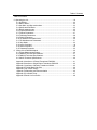
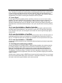
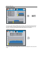
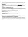
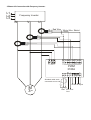
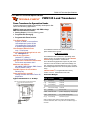
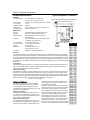
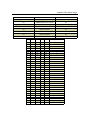
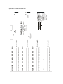
TECHNA-CHECK®
MODEL 3200
Tool Monitoring System
Technical Documentation
Released: August 2005
Contents
© Copyright 2003-2005, Techna-Tool Inc., Hartland, Wisconsin, USA.
The information in this document is subject to change without notice.
TECHNA-CHECK® is a registered trademark of Techna-Tool Inc.
Table of Contents
Table Of Contents:
1. The Concept............................................................................................................. 5
2. Key Benefits ............................................................................................................. 6
3. Function ................................................................................................................... 7
3.1 General .............................................................................................................. 7
3.2 Learn Signal ....................................................................................................... 8
3.2.1 Learn Cycle Initiation -- Machine Controlled............................................. 8
3.2.2 Learn Cycle Initiation -- Face Plate........................................................... 8
3.2.3 Learn Cycle Initiation -- TOOLMON.......................................................... 8
3.3 Fault Signals and Resetting of Faults ................................................................ 8
3.4 Analog Zoom Function....................................................................................... 9
3.5 Missing Tool Supervision ................................................................................... 10
3.5.1 Missing Tool—Absolute Mode .................................................................. 10
3.5.2 Missing Tool—Learn Work Mode ............................................................. 11
3.6 Tool Break Supervision...................................................................................... 12
3.6.1 Break Mode Selection............................................................................... 12
3.6.2 Tool Break—Absolute Peak Mode............................................................ 12
3.6.3 Tool Break—Learn Peak Mode ................................................................ 13
3.6.4 Tool Break—Absolute Peak Curve ........................................................... 14
3.7 Blunt Tool Supervision ....................................................................................... 15
3.7.1 Blunt Mode Selection ................................................................................ 15
3.7.2 Blunt Tool—Absolute Peak Mode............................................................. 16
3.7.3 Blunt Tool—Learn Peak Mode.................................................................. 17
3.7.4 Blunt Tool—Learn Peak Mode.................................................................. 18
3.7.5 Blunt Tool—Blunt On Part Count.............................................................. 19
3.7.6 Blunt Tool– Resetting the Part Counter .................................................... 19
3.8 Idle Limit Supervision......................................................................................... 20
3.9 Touch Point Limit Function ................................................................................ 21
4. Installation Notes ...................................................................................................... 22
4.1 Mechanical Mounting ......................................................................................... 22
4.2 Electrical Connection.......................................................................................... 22
4.2.1 Power ........................................................................................................ 22
4.2.2 Control Inputs ............................................................................................ 22
4.2.3 Control Outputs ......................................................................................... 22
4.3 Wiring of the PWM350 Module........................................................................... 22
4.3.1 Current Measurement Range.................................................................... 22
Table of Contents
Table Of Contents:
5. Operating the unit ....................................................................................................... 23
5.1 On/Off Key.......................................................................................................... 23
5.2 Station Select ..................................................................................................... 23
5.3 Auto Man. and Stop mode select ....................................................................... 23
5.4 Spindle and Roll Mode ....................................................................................... 25
5.5 Spindle expand mode......................................................................................... 25
5.6 F1-Break Parameters ......................................................................................... 26
5.7 F2-Blunt Parameters .......................................................................................... 27
5.8 F3-Missing Parameters ...................................................................................... 28
5.9 F4-Idle Parameters............................................................................................. 29
5.10 F5-Measurement Parameters .......................................................................... 30
5.11 F6-Miscellaneous Parameters.......................................................................... 31
5.12 Stop Mode ........................................................................................................ 32
5.13 Learn Command............................................................................................... 33
5.14 Reset Command............................................................................................... 34
5.15 Password Protection ........................................................................................ 35
6. Wiring of the PWM350 Module................................................................................. 36
6.1 Current Measurement Range............................................................................. 36
6.2 PWM350 Technical Specifications ..................................................................... 37
6.3 PWM125 Technical Specifications ..................................................................... 38
6.4 VM100 Technical Specifications ........................................................................ 40
Appendix A-Interface to 3-Phase Transducer-PWM350 .......................................... 41
Appendix B-Interface to Single-Phase Transducer-PWM125 .................................. 42
Appendix C-Interface to Vibration Transducer-VM100 ............................................ 43
Appendix D-TC3200 Back Side Print ....................................................................... 44
Appendix E-Dip. Switch Usage ................................................................................ 45
Appendix F-Networking and Communication .......................................................... 46
Appendix G-Cut Select Chart ................................................................................... 47
Appendix G-Panel Cut-Out Profile ........................................................................... 48
The Concept
1. The Concept
St St St 1 2
TT St
1 2 3 4 34
% #1 Drill 8mm
100
75
50
25
Auto
3200
V1.3
% #1 Drill 6mm
100
75
50
25
s
s
% #1 Miller
100
75
50
25
% #1 Step Tool
100
75
50
25
s
s
The TECHNA-CHECK® TC3200 is a modular Tool Monitoring system.
The TC3200 is hardware configurable and is able to monitor 1/2/3 or 4 tooling spindles (stations).
The stations are electrically isolated and can be used with (4) machines in a cell.
The TECHNA-CHECK® TC3200 has been exclusively developed for the supervision of cutting
tools on single spindle automatic machine tools. It is capable of detecting missing, blunt,
and broken or damaged tooling. The TC3200 measures, from external measurement transducer
(s), the electrical power consumption of the spindle motor. A blunt (or worn) tool needs more energy to complete a machining cycle, and when a tool breaks a short energy peak or spike is created. If no tool is present, the power consumption drops back to the idle power of the spindle.
The TC3200 is designed to monitor motor power in the primary or secondary of a variable frequency motor drive (see the specification of the external measurement transducer PWM 325). It is
also capable of storing 64 complete sets of monitoring parameters. These features make it ideal
for monitoring flexible transfer machines utilizing single spindle CNC heads.
The unit may be interfaced and operated from a PC through its RS232 or RS485 interface. The
TOOLMON application adds statistic features to the tool monitoring. The function of the TOOLMON application is covered by a separate manual.
A vibration sensor (VM100) makes it possible to monitor spindles for excessive vibrations also.
Key Benefits
2. Key Benefits
Improved part quality
The detection of missing or broken tools helps insure that the proper machining is being performed. Detection of tool wear and damage can help improve surface finish and tolerances.
Maximized tool life
By detecting for tool wear and damage, expensive tooling can be changed before the damage gets
too severe. This detection also reduces dependence on hit or miss part counting schemes.
Protection of spindle and feed mechanism
By detecting catastrophic tool failures, the TECHNA-CHECK® Model 3200 can prevent serious
damage to your head and feed mechanisms, not just at the station being monitored, but at downstream stations where "chain reaction" effects can occur.
Improved up time
By creating the process improvements listed above, TECHNA-CHECK® Model 3200 keeps your
machine running longer.
Easy installation
No mechanical modification of the machinery is necessary. The entire system mounts easily in
your electrical cabinet.
Function
3. Function
3.1 General
Figure 1 shows typical power consumption on a machine spindle during a machining cycle. The
first power peak, which is caused by a change in motor speed or a motor start, is not monitored at
all. Only the portion of the cut where the spindle speed is constant and the tool is actually in cut is
monitored by the unit. When the machine head begins to move towards the part, a "Start" Signal
is generated by the machine which tells the TECHNA-CHECK® Model 3200 that a new cycle is
beginning. When the unit receives the start signal, the green Start LED is illuminated, and the
user-defined Start Delay, Ts, is activated.
Figure 1 -- Function
Consumption
P = f(t)
Ta = 0.0 (Off) - 999,9 Sec.
Break-limit
Blunt-limit
Missing-limit
Measurement
Ts
Start Delay
Start
Idle consumption
Po
0 (Off) -250 samples
Supervision Active
t(s)
When the start delay ends, the unit initiates the idle power measurement. It is very important to
measure the idle power before the tool begins cutting the part. The idle power consumption, Po,
is the portion of work done by the machine not going into the cut. Idle power consumption will vary
normally during the course of the day due to such factors as friction, temperature, oil and grease
viscosity, etc. The idle power is calculated as an average of a number of power measurements
taken over a user-defined number of half electrical cycles (in North America, there are 60 electrical
cycles per second). The number of samples (half electrical cycles) used to calculate the idle power
is user set as the value of Po Averaging. Minimum and maximum values of Idle Power, PoMin
and PoMax may be set.
After the idle power measurement, the tool monitoring becomes active. The duration of monitoring
may be limited through the use of the monitoring timers, Ta and Tw , in order to avoid monitoring
undesired events, such as motor speed changes. In many cases, these timers may be turned off,
allowing monitoring for as long as the start signal is present. The TECHNA-CHECK® Model 3200
includes a user programmable Power Averaging feature, which sets the number of individual
power measurements which are averaged into one calculated value (again, the number of power
measurements are related to the frequency of the supply power). This averaging can be used to
"smooth" very noisy electrical signals, but it should be set as low as possible in order not to filter
out very short duration power surges caused by tooling problems. The TECHNA-CHECK® Model
3200 includes a unique Analog Zoom Function, which greatly improves the monitoring of small
tools. Refer to the section on "Analog Zoom Function" for details.
Function
The TECHNA-CHECK Model 3200 is capable of monitoring 64 completely different cutting operations. This feature is useful when making multiple machining passes with the same machine head,
or when making several different parts on the same machine. Prior to the Start Signal being received, the machine signals the unit with six input signals, Cut # Select, which cause the appropriate parameters to be used in monitoring the subsequent machine operation.
3.2 Learn Signal
For each type of monitoring (Missing, Break, and Blunt), there are one or more “Learn” modes
available. The Learn modes allow the monitoring to change to take into account variations in tool
grind from one tool to the next. In most applications, when using Learn modes, a Learn cycle
should be initiated whenever the tool is changed. A Learn cycle may be initiated in three ways, as
described below. It should be noted that during a Learn cycle, only Idle Power monitoring is taking
place.
3.2.1 Learn Cycle Initiation -- Machine Controlled
A Learn cycle may be initiated by the machine controller. If the Start signal is made active while
the Reset signal is being held active, the cycle will be a Learn cycle. If an Idle Power fault would
occur during the Learn cycle, the reset signal must be taken low, then brought back high again to
reset the fault.
3.2.2 Learn Cycle Initiation -- Face Plate
A Learn cycle may be initiated from the keyboard on the face plate of the unit. With the system not
password protected, the learn key is pressed once. The display shows “press enter to learn current cut”. To initiate the Learn cycle, the enter key is pressed. The next cycle will be a Learn cycle.
3.2.3 Learn Cycle Initiation -- TOOLMON
A Learn cycle may be initiated from the TOOLMON software package by pressing the appropriate
function key.
3.3 Fault Signals and Resetting of Faults
All faults generated by the TECHNA-CHECK® Model 3200 are signaled to the machine controller
by normally closed dry contact relays (refer to the section on "Electrical Connection"). The Tool
Break and Tool Missing faults share a common relay. It is typical that the machine will be programmed to stop its present cycle immediately and retract the machine head on detection of a
Tool Missing or Tool Break condition. The Blunt Tool fault is signaled by a second relay. It is typical that the machine will be programmed to finish the current cycle before stopping the machine on
a Blunt Tool fault.
All faults may be reset by using the RESET button located on the front panel of the unit, or through
the use of the external Reset input (refer to the section on "Electrical Connection"). The fault relays
will remain in their active (open) condition until a reset is received.
Analog Zoom Function
3.4 Analog Zoom Function
Prior to setting the monitoring parameters, it is desirable to set up the Analog Zoom Function
parameters. The Analog Zoom Function enables the TECHNA-CHECK® Model 3200 to monitor
even very small tools by "focusing" the unit's full analog to digital conversion resolution into a narrow band of power consumption. To set the parameters, it is most helpful to use the TMSMON
support software (see below). Note that the Analog Zoom Function should be set up prior to setting monitoring parameters, as the monitoring parameters will be "re-scaled" if changes are made
to the Analog Zoom.
The current measurement range must first be set. The current measurement range is set by
hard-wiring pins 4 and 5 on the PWM350 module (see Appendix A for wiring diagram). Once the
current measurement range has been set, then any large idle powers may be subtracted from the
display by adjusting P1Min so that the idle is only 5% to 10% of the full load. P1Max may then be
adjusted so that the cutting torque is a rise of 10% to 20% above idle.
Figure 2 shows a hypothetical application to highlight the power of the Analog Zoom Function. In
this application, a 380 VAC, three phase motor is being monitored. If the Current Range is set to
10 A, then 100% power is equivalent to 6.58 kW. If a small tool with a high spindle speed is being
used, it is entirely possible that the idle power may be as high as 50% of the scale, while the cutting torque may only rise 2% or 3%. In order to maximize the ability to monitor this application,
P1Min is "zoomed" to 50%, while P1Max is "zoomed" to 60%. The entire resolution of the unit is
now concentrated in a 10% band. The unit is now only monitoring between 3.29 kW and 3.95 kW.
The cutting torque will appear to be 10 times bigger.
Figure 2 -- Analog Zoom Function
Tool Missing
3.5 Missing Tool Supervision
3.5.1. Missing Tool -- Absolute Mode
Figure 3 shows how the missing tool detection, absolute mode, is set up relative to a typical machining cycle. The Missing Mode, parameter 5, defines the type of Missing Tool Limit which will
be set. In the Absolute mode, the Missing Tool Limit is a user-defined absolute torque rise above
idle. The power consumption during the machining cycle must remain above the limit for a cumulative time longer than the Missing Delay, Trm. (Note that the cumulative nature of this measurement means that brief power dips below the Missing Limit will not cause a fault as long as the TOTAL amount of time spent above the Missing Limit is greater than the Missing Delay.) In the event
of a missing tool fault, a red 1 will appear in the missing window and the particular station number
will flash red. Missing Tool supervision remains active for the duration of Tw, if Tw is enabled. If
Tw is turned off, Missing Tool supervision remains active the entire time the start signal is present,
following the Start Delay and the idle power measurement.
Figure 3 -- Tool Missing Absolute Mode
Consumption
P = f(t)
Tw = 0,0 (Off) - 999,9 Sec.
Trm = 0,1 - 25,0 Sec.
Tool-Missing-limit
is an absolute
percentage > Po
Ts
Start Delay
Start
Po
0 (Off) - 250 Samples
Supervision Active
t(s)
In determining appropriate values for the Missing Limit and Missing Delay, more aggressive monitoring can be achieved with higher Missing Limits and longer Missing Delays (in other words, for a
good cycle, the power must stay higher longer). However, setting these parameters too aggressively can result in more frequent nuisance trips. A good compromise and starting point for adjustment seems to be to set the Missing Limit fairly low, around 3 - 5 % (since if the tool is missing,
there will be NO rise above idle), and to set a Missing Delay of about 3/4 of the total machining
time. Better results seem to be achieved by leaving the Missing Limit low, and tuning out nuisance
trips by adjusting the Missing Delay.
The ‘Time-Over-Missing’ is displayed on the screen when no Missing Alarm is present. This makes
it easier to fine-tune the setting of the Missing Delay.
Tool Missing
3.5.2 Missing Tool -- Learn Work Mode
Figure 4 shows how the missing tool detection, Learn Work mode, is set up relative to a typical
machining cycle. In the Learn Work mode, the Missing Tool Limit is a user-defined relative percentage of the work calculated during the Learn cycle. If the work calculated during a cycle does
not exceed this percentage of the learned work, then a Missing alarm is generated. In the event of
a missing tool fault, a red 1 will appear in the missing window and the particular station number will
flash red. Missing Tool supervision remains active for the duration of Tw, if Tw is enabled. If Tw is
turned off, Missing Tool supervision remains active the entire time the start signal is present, following the Start Delay and the idle power measurement.
Figure 4 -- Tool Missing Learn Work Mode
Consumption
P = f(t)
Tw = 0,0 (Off) - 999,9 Sec.
Ts
Start Delay
Start
Po
0 (Off) - 250 Samples
Supervision Active
t(s)
Setting these parameters too aggressively can result in more frequent nuisance trips. A good compromise and starting point for adjustment seems to be to set the Missing Limit fairly low, around 30
- 50 % (since if the tool is missing, there will be NO rise above idle).
Tool Break
3.6 Tool Break Supervision
3.6.1. Break Mode Selection
When a tool breaks while it is machining a part, it is typical to notice a sharp, short duration "spike"
of torque in the motor. This torque spike is the extra energy being used by the machine to actually
break the tool. The TECHNA-CHECK® Model 3200 can detect this spike, and indicate a broken
tool. (It should be noted that not all tools break the same way every time, and that a torque spike
may not necessarily be generated in the process of breaking the tool. In this case, a missing tool
condition should be noticed on the following cycle.)
There are three Break Modes available, Absolute Peak Mode, Absolute Peak Curve Mode, and
Learn Peak Mode, which are described below.
3.6.2. Tool Break -- Absolute Peak Mode
Figure 5 shows a typical tool break situation, including the setting of the tool Break Limit. The
Break Limit is a user-defined percentage increase above the Idle Power. If the Break Limit is exceeded for a cumulative time greater than the user-defined Break Delay, Trb, then a tool break
fault will be generated. In the event of a broken tool fault, a red 1 will appear in the broken window
and the particular station number will flash red. Tool Break supervision remains active for the duration of Tw, if Tw is enabled. If Tw is turned off, Tool Break supervision remains active the entire
time the start signal is present, following the Start Delay and the idle power measurement.
Figure 5 -- Absolute Peak Break Mode
Ta = 0.0 (Off) - 999,9 Sec.
P = f(t)
Consumption
Trb = 0.0 - 25.0 sec.
Break-limit
1-100%
> Po
Measurement
Ts
Start Delay
Start
Po
0(Off) - 250 Samples
Supervision Active
t(s)
Break-alarm
Reset (I1)
In setting the Break Limit and Break Delay, more aggressive monitoring is achieved by setting a
lower limit and shorter delay. However, setting these parameters too aggressively will result in increased nuisance trips. In typical applications, the Break Limit is set fairly high (between 20 and
30%), but with a very short Break Delay (often the minimum 0.01 second). When a tool break occurs, the rise in torque is often quite dramatic, so a high limit and short delay are best to eliminate
nuisance faults.
Tool Break
3.6.3 Tool Break -- Learn Peak Mode
Figure 6 shows a typical tool break situation, including the setting of the tool Break Limit in Learn
Mode. The Break Limit in Learn Mode is a user-defined percentile increase of the power consumption above the Idle Power PLUS the Learned peak power. If the Break Limit is exceeded for a cumulative time greater than the user-defined Break Delay, Trb, then a tool break fault will be generated. In the event of a missing tool fault, a red 1 will appear in the missing window and the particular station number will flash red. Tool Break supervision remains active for the duration of Ta, if Ta
is enabled. If Ta is turned off, Tool Break supervision remains active the entire time the start signal
is present, following the Start Delay and the idle power measurement.
Figure 6 -- Learn Peak Break Mode
Ta = 0.0 (Off) - 999,9 Sec.
P = f(t)
Consumption
Trb = 0.0 - 25.0 sec.
Break-limit
1-100%
> Po + Learn Peak
Measurement
Ts
Start Delay
Start
Break-alarm
Reset (I1)
Po
0(Off) - 250 Samples
Supervision Active
t(s)
Setting the Break Limit and Break Delay in Learn Mode is much the same as in the Absolute Peak
Mode, except that the Break Limit in Learn Mode will “move” with respect to the learned cut. This
adaptation allows the unit to adjust to changes in grind from one tool to the next, when the profile
is re-learned.
Tool Break
3.6.4 Tool Break -- Absolute Peak Curve Mode
The Absolute Peak Curve mode works just like Absolute Peak Mode (sec. 3.6.2), but the limit
changes in a step fashion as a function of time. This mode may well be used to supervise step
tools. If the Break Limit is exceeded for a cumulative time greater than the user-defined Break Delay, Trb, then a tool break fault will be generated. Tool Break supervision remains active for the
entire time, following the Start Delay and idle power measurement, that the Start Signal is present
on the unit if monitoring timer Ta is turned off, or for the duration of Ta if it is enabled. Three steps
are available and if a step limit is set to zero it is not monitored at all
Figure 7 -- Absolute Peak Curve Mode
Ta = 0.0 (Off) - 999,9 Sec.
P = f(t)
Consumption
Trb = 0.0 - 25.0 sec.
Break-limit =
3 step curve
0 (Off)-100%
> Po
Measurement
Ts
Start Delay
Start
Po
0(Off) - 250 Samples
Supervision Active
t(s)
Break-alarm
Reset (I1)
In setting the Break Limit and Break Delay, more aggressive monitoring is achieved by setting a
lower limit and shorter delay. However, setting these parameters too aggressively will result in increased nuisance trips. In typical applications, the Break Limit is set fairly high (between 25 and
50%), but with a very short Break Delay (often the minimum 0.01 second). When a tool break occurs, the rise in torque is often quite dramatic, so a high limit and short delay would be best to
eliminate nuisance faults.
Note! This mode may well be used to monitor threading operations. The first step is used to monitor the forward threading and the middle step is set to zero, while the direction of the tool changes
and the last step is then used to supervise the reverse threading (pulling the threading tool out of
the part).
Tool Blunt
3.7 Blunt Tool Supervision
3.7.1 Blunt Mode Selection
As a tool wears, it is normal for its cutting surfaces to become less efficient, and thus it requires
more torque to cut the part. The TECHNA-CHECK® Model 3200 is designed to look for this rise in
torque, and to stop the machine when a tool has reached a point where it would be desirable to
change it.
There are three Blunt Modes. If Absolute Peak Mode is selected, the detection of blunt tools is
based on the value of the instantaneous torque measurement above idle. In Work Mode, the detection of blunt tools is based on the area under the torque curve for the duration of the cutting
cycle, which is proportional to the work or energy used to cut the part. Peak Mode is recommended for most simple machining operations. Work Mode may be used when there are multiple
or changing load levels observed during the cycle, such as when a step tool or complicated boring
tool is used. Additionally, there are two Blunt Modes representing Learn versions of the two
modes already described. They allow the system to automatically adjust to changes in grind from
one tool to the next.
In any blunt mode, the use of the Show Statistics option from the TOOLMON software package is
helpful in setting appropriate values for the Blunt Limit. When a computer running TOOLMON is
connected to the TECHNA-CHECK® Model 3200, it is continually keeping track of the peak torque
or work used in each cycle. This data may be viewed in the Show Statistics display. This display
will give you an idea, over time, of how the tool has worn, and where an appropriate Blunt Limit
may be set.
Also in any blunt mode, the Blunt Counter feature is available. In order to reduce the number of
undesired nuisance trips, the Blunt Counter may be set to require a number of consecutive blunt
tool faults to be detected before the machine is signaled to stop. For example, a hard part or temporary chip build up may cause a blunt fault to occur in one cycle, but the condition may not be
present again in the next cycle. In this case, a Blunt Counter setting of, for example, three would
require this condition to occur three cycles in a row before a blunt trip stops the machine. In typical
applications, a Blunt Counter setting from 2 to 5 is generally used, depending on material consistency and chip build-up, but higher settings may be used.
Tool Blunt
3.7.2 Blunt Tool – Absolute Peak Mode
Figure 8 shows a typical blunt tool situation using Absolute Peak Mode monitoring, including the
setting of the tool Blunt Limit. The Blunt Limit is a user-defined percentage increase above the Idle
Power. If the Blunt Limit is exceeded for a cumulative time greater than the user-defined Blunt
Delay, Trs, then a tool blunt fault will be generated. In the event of a blunt tool fault, a red number
will appear in the blunt window and the particular station number will flash red. Blunt Tool supervision remains active for the duration of Tba, if Tba is enabled. If Tba is turned off, Blunt Tool supervision remains active the entire time the start signal is present, following the Start Delay and the
idle power measurement.
Figure 8 – Absolute Peak Blunt Mode
Ta = 0.0 (Off) - 999,9 Sec.
Tba = 0.0 (Off) - 999,9 Sec.
Trb = 0.0 - 25.0 sec.
Consumption
P = f(t)
Blunt-limit
1-100%
> Po
Measurement
Ts
Start Delay
Start
Po
0(Off) - 250 Samples
Supervision Active
t(s)
Blunt-alarm
Reset (I1)
In setting the Blunt Limit and Blunt Delay, more aggressive monitoring is achieved by setting a
lower limit and shorter delay. However, setting these parameters too aggressively will result in increased nuisance trips. As a tool wears, the load will gradually increase, and will eventually stay at
a higher level for the entire duration of the cut. In typical applications, the Blunt Limit is set fairly
low (between 10 and 25%), but with a fairly long Break Delay (often around 75% of the total duration of the cut). Adjustments are then made based on data from the Show Statistics display, usually leaving the Blunt Delay alone, but changing the Blunt Limit.
Tool Blunt
3.7.3 Blunt Tool - Learn Peak Mode
Figure 9 shows a typical blunt tool situation using Learn Peak Mode monitoring, including the setting of the tool Blunt Limit. The Blunt Limit is a user defined percentile increase above the Idle
Power PLUS the Learned Peak. If the Blunt Limit is exceeded for a cumulative time greater than
the user-defined Blunt Delay, Trs, then a tool blunt fault will be generated. In the event of a blunt
tool fault, a red number will appear in the blunt window and the particular station number will flash
red. Blunt Tool supervision remains active for the duration of Tba, if Tba is enabled. If Tba is
turned off, Blunt Tool supervision remains active the entire time the start signal is present, following the Start Delay and the idle power measurement.
Figure 9 -- Learn Peak Blunt Mode
Ta = 0.0 (Off) - 999,9 Sec.
Tba = 0.0 (Off) - 999,9 Sec.
Trb = 0.0 - 25.0 sec.
Consumption
P = f(t)
Blunt-limit
1-100%
> Po + Learn Peak
Measurement
Ts
Start Delay
Start
Blunt-alarm
Reset (I1)
Po
0(Off) - 250 Samples
Supervision Active
t(s)
Setting the Blunt Limit and Blunt Delay in Learn Peak Mode is much the same as setting them in
regular Peak Mode. The addition of the Learn function means that the monitoring limit will automatically adjust for variations in grind from tool to tool.
Tool Blunt
3.7.4 Blunt Tool - Learn Work Mode
Figure 10 shows a typical blunt tool situation using Learn Work Mode monitoring, including the
setting of the tool Blunt Limit. The work, or energy consumed, during the cutting cycle is proportional to the black area in the Figure. The Blunt Limit is a user-defined percentage increase above
the Learned Work. A fault is generated if the measured work exceeds the percentage increase
over the Learned Work (note that the Blunt Delay becomes inactive in Work Mode). In the event of
a blunt tool fault, a red number will appear in the blunt window and the particular station number
will flash red. Blunt Tool supervision remains active for the duration of Tba, if Tba is enabled. If
Tba is turned off, Blunt Tool supervision remains active the entire time the start signal is present,
following the Start Delay and the idle power measurement. Because Work Mode monitoring calculates total energy used in the entire cycle, any faults will always be signaled at the end of the cycle.
Figure 10 -- Learn Work Blunt Mode
Ta = 0.0 (Off) - 999,9 Sec.
P = f(t)
Consumption
Tba = 0.0 (Off) - 999,9 Sec.
Blunt-limit
101-999%
> Learn Work
Ts
Start Delay
Start
Blunt-alarm
Po
0(Off) - 250 Samples
Supervision Active
t(s)
Reset (I1)
Setting the Blunt Limit in Learn Work Mode is much the same as setting the limit in regular Work
Mode. The Learn feature gives the system the ability to adjust monitoring for differences in tool
grind from one tool to the next.
Tool Blunt
3.7.5 Blunt Tool - Blunt On Part Count
Each cut is counted by the TC3200. This part count may even be used to generate a Blunt Alarm.
The number of parts to generate a Blunt Alarm is programmable form the front (see. Blunt Menu)
or from the TOOLMON application. The ‘Blunt On Part#’ function must be enabled as well.
3.7.6 Blunt Tool - Resetting the Part Counter
The part counter is reset to zero when a new learn is done.
The part counter may also be set to zero from the TC3200 front. When no Alarm is present the
Reset Button is used to reset the part counter.
Same function in TOOLMON. If no alarm is present the Reset Alarm is used to reset the part
counter.
Idle Monitoring
3.8 Idle Limit Supervision
In some applications, it may be necessary to check that the machine idle power is within certain
boundaries. For example, a very low idle power may indicate that a belt is broken or that there is
no power to the motor. A very high idle power may also indicate belt problems, or problems with
lubrication or bearings. In these cases, a high and low limit, IdleMax and IdleMin, for the idle power
may be set. After the idle power is measured and Po is calculated, the value is compared with IdleMax and IdleMin. If it is not within the limits, then a Tool Break fault occurs immediately.
Each of the Idle Power Monitoring limits may be disabled by turning them all the way down to zero.
Figure 11 -- Idle Limits
Consumption
P = f(t)
Idle Limit
1-100% Absolute
Measurement
Idle Min. Limit
1-100% Absolute
Ts
Start Delay
Start
Break-relay
Po
0(Off) - 250 Samples
Supervision Active
t(s)
Touch Point Limit
3.9 Touch Point Limit Function
Relay #3 output may be used as a touch point indication. If a Touch Point Limit greater than zero
has been programmed the relay no. 3 contacts are closed when the power consumption reaches
a threshold equal to Po + Touch Point Limit. The relay #3 contacts are released again, when the
start signal is removed.
This function may be used, in some systems to tell the tool feed mechanism that a tooling operation has begun and the feed rate needs to be decreased. The tooling cycle may be shortened if a
different, faster feed rate, can be used until the tool touches the target.
Figure 12 -- Touch Point Limit
Ta = 0.0 (Off) - 999,9 Sec.
Consumption
P = f(t)
Measurement
Touch Point Limit
1-100%
> Po
Ts
Start Delay
Start
Touch-relay
Po
0(Off) - 250 Samples
Supervision Active
t(s)
Installation Notes
4. Installation Notes
4.1 Mechanical Mounting
The TECHNA-CHECK® Model 3200 mounts simply through the electrical cabinet or an optional
enclosure can be supplied. The PWM350 module mounts inside the electrical cabinet using standard 35mm DIN rail. It is typical to mount this unit directly beneath the motor drive or starter, since
the motor cables are routed through the holes in the unit.
4.2 Electrical Connection
4.2.1 Power
Electrical connections to the TECHNA-CHECK® Model 3200 and PWM350 are as shown in Appendix A. The current measurement input on the unit is rated for motors with full load ratings up to
the rating of the PWM350 module.
4.2.2 Control Inputs
All control inputs to the module are 24 VDC PLC inputs. In cases where relay logic is used, it may
be necessary to set a Debounce Delay, which will allow the system to ignore any bouncing of mechanical relay contacts at the inputs.
4.2.3 Control Outputs
Fault conditions are signaled to the machine by two sets of relay contacts. In typical applications,
the Break/Missing relay is wired to cause an immediate retraction of the machine head, and the
Blunt relay is wired to allow the machine to complete its current cycle before stopping the machine.
Because the outputs are relays, they will wire into almost any machine control system, whether it
uses relay logic or a PLC. It should be noted that the output relays will be open when the unit is
not powered.
4.3 Wiring of the PWM350 Module
For proper operation of the system, it is important that the PWM350 be set up properly. Incorrect
settings of Current Measurement Range may severely reduce the functionality of the system.
4.3.1 Current Measurement Range
The current measurement range is set by applying 24 VDC input signals to pins 4 and 5, according
to the logical diagram shown in Appendix A. The appropriate measuring range is selected by determining the Full Load Amps (FLA) of the motor, which should be marked on the motor housing.
Then the percentage of the rating of the PWM350 should be calculated. For example, when using
a motor with an FLA rating of 5 Amps with a PWM350 rated at 25 A, the percentage of the
PWM350 rating would be 20%. In this case, the 20% range on the PWM350 would be used. In
cases where the percentage does not exactly correspond to one of the current ranges on the unit,
the next larger range should be used.
It should also be noted that it is permissible to use external current transformers (CT’s) in cases
where the motor current is above the rating of the PWM350. As an example, if it were desired to
monitor a motor having an FLA of 100 Amps, a 20:1 current transformer might be employed. Since
the CT has a ratio of 20:1, the maximum current on its secondary would be 5 Amps. Applying the
example above, the current measurement range would be set to 20%
Operating the unit
5. Operating the unit
5.1 On/Off key
On/Off
The On/Off key may be used to switch the display On/Off, only if the machine is not running. If the
display is turned off, it will be switched on again as soon as one of the stations is activated (startsignal active). A parameter ‘Backlight On Period’ is used to program how long the display will stay
on after the start signal has been removed or a key has been activated. Switching off the display
when the machine is not running increases the lifetime of the display. When the display is
switched off (black) the green On/Off LED will be flashing.
5.2 Station Select
Station
Select
1
2
3
4
1
3
2
4
The 4 station select keys are used to select the station, which will be displayed. If a channel is not
hardware activated (not present), it cannot be selected. There also is a button for selecting a display of all channels simultaneously. Some of the actions that are carried out from the keyboard
require a single station to be displayed. The ‘Reset’ command can only be issued while a single
station is selected, while the reset will only apply to the currently displayed channel. The same is
true for the ’Learn’ command and the ‘Parameter Modify’ command.
5.3 Auto, Man. and Stop mode select
Auto
Man.
Stop
In Auto mode the display follows the current operation cycle of the machine tool. When the machine selects a new tool (cut) the display Automatically displays this cut. In manual mode the
user is allowed to select/display and alter other cuts rather than the currently active cut. When
Manual mode is selected the bottom half of the display is used to select the cut.
Manual mode
St St St 1 2
TT St
1 2 3 4 34
Cut# 0
Po%
39
Pp%
28
Work% 133
Break 0
Miss 4,52 s
Blunt 0(2)
Part# 94569
3200
V1.2
Man
% #1 Cut #11
100
75
50
25
#00
#01
#02
#03
#04
#05
#06
#07
Cut #08
Cut #09
Cut #10
Cut #11
Cut #12
Cut #13
Cut #14
Cut #15
F2
Blunt
F3
Missing
s
Manual Cut Select - Station 1, 64 Cuts
Cut
Cut
Cut
Cut
Cut
Cut
Cut
Cut
F1
Break
Cut #16
Cut #17
Cut #18
Cut #19
Cut #20
Cut #21
Cut #22
Cut #23
F4
Idle
F5
Param
F6
In Manual mode the arrow keys are used to select a cut. As soon as a cut is selected its last profile is displayed in the spindle window in the upper half of the screen. If a Parameter key is activated the parameter for the cut selected may be viewed or modified. In manual mode it is possible
to display the LAST ALARM cut also.
Spindle and Roll mode
5.4 Spindle and Roll mode
St St St 1 2
TT St
1 2 3 4 34
Cut#
Po%
Pp %
Work%
Break
Miss
Blunt
Part#
0
39
28
133
0
4,52 s
0(2)
94569
3200
V1.2
Auto
% #1 Drill 8mm
100
75
50
25
s
R
>>
[%]
100
75
50
25
[s]
The ‘R’ key is used to select this display mode. The bottom of the screen shows all measurement
in a ‘Rolling’ fashion. This display may be used when analyzing, if the start signal appears at the
right point. The rolling may be stopped and started again by two keys on the panel.
5.5 Spindle expand mode
St St St 1 2
TT St
1 2 3 4 34
Cut#
Po%
Pp %
Work%
0
39
28
133
3200
V1.3
Auto
Break
Miss
Blunt
Part#
0
4,52s
0(2)
94569
% #1 Drill 8mm
100
S
75
50
25
s
The ‘S’ key is used to select this display mode. The whole screen displays the current cycle (zoom
mode).
F1—Break Parameters
5.6 F1—Break Parameters
St St St 1 2
TT St
1 2 3 4 34
Cut#
Po%
Pp%
Work%
Break
Miss
Blunt
Part#
Auto
3200
V1.2
% #1 Drill 8mm
100
0
39
28
133
0
4.52 s
0(2)
94569
75
50
1
2
3
ABC
DEF
GHI
4
5
6
JKL
MNO
PQR
7
8
9
ST
UVW
XY
0
.
Z
25
Fn1 Fn2 Fn3
s
PARAMETERS - Tool Break Parameters
Station# 1, Drill 8mm, v. 1.4
1.Break
2.Break
3.Break
4.Break
5.Break
6.Break
7.Break
Mode
Limit
Limit
Limit
Point
Point
Delay
1
2
3
1
2
[%]
[%]
[%]
[s]
[s]
[s]
=
=
=
=
=
=
=
Abs. Peak
40
45
50
2.0
3.0
0.0
A parameter is selected by the arrow-up and down keys. The enter key may be pushed to activate the parameter. When activated the arrow-up and down key may be used to alter the variable. When the enter-key is activated again the modification is made permanent. The numerical
keys may also be used to alter a variable. The enter-key or the arrow-up/down keys are used to
make the change permanent.
Parameter
Range
1. Break Mode
Abs. Peak
Learn Peak
Abs. Peak Curve
2. Break Limit1 [%]
Break Limit 1 (0-100)%, 0 = Off
3. Break Limit2 [%]
Break Limit 2 (0-100)%, 0 = Off
Active only in Abs. Peak Curve mode
4. Break Limit3 [%]
Break Limit 3 (0-100)%, 0 = Off
Active only in Abs. Peak Curve mode
5. Break Point 1 [s]
Break Point 1 (0.0-999.9 seconds)
Active only in Abs. Peak Curve mode
6. Break Point 2 [s]
Break Point 2 (0.0-999.9 seconds)
Active only in Abs. Peak Curve mode
7. Break Delay [s]
Break Delay (0.0-25.0 seconds)
Break Reaction Time-Keep as low as possible
F2—Blunt Parameters
5.7 F2—Blunt Parameters
TT
St St St St 1 2
1 2 3 4 34
Cut#
Po%
Pp%
Work%
Break
Miss
Blunt
Part#
Auto
3200
V1.2
% #1 Drill 8mm
100
75
0
39
28
133
0
4.52 s
0(2)
94569
1
2
3
ABC
DEF
GHI
4
5
6
JKL
MNO
PQR
7
8
9
ST
UVW
XY
0
.
50
Z
25
s
Fn1 Fn2 Fn3
PARAMETERS - Tool Blunt Parameters
Station# 1, Drill 8mm, v. 1.4
1.Blunt
2.Blunt
3.Blunt
4.Blunt
5.Blunt
6.Blunt
7.Blunt
Mode
Limit
[%]
Delay
[s]
Count
Duration [s]
On Part#
Part# Limit
=
=
=
=
=
=
=
Abs. Peak
33
2.0
1
0.0
Disable
100000
A parameter is selected by the arrow-up and down keys. The enter key may be pushed to activate the parameter. When activated the arrow-up and down key may be used to alter the variable. When the enter-key is activated again the modification is made permanent. The numerical
keys may also be used to alter a variable. The enter-key or the arrow-up/down keys are used to
make the change permanent.
Parameter
Range
1. Blunt Mode
Abs. Peak
Learn Peak
Learn Work
2. Blunt Limit [%]
Blunt Limit (0-100%), 0 = Off
Blunt Limit (101-999%), Learn Work Mode
3. Blunt Delay [s]
Blunt Delay (0.0-25.0 seconds)
Active only in Abs. Peak and Learn Peak mode
4. Blunt Count
Blunt Count (1-15 cont. cycles)
5. Blunt Duration [s]
Blunt Duration (0.0-999.9 seconds), 0.0 = Off
6. Blunt On Part#
Enable
Disable
7. Blunt Part# Limit
(100-1000000)
F3—Missing Parameters
5.8 F3—Missing Parameters
TT
St St St St 1 2
1 2 3 4 34
Cut#
Po%
Pp %
Work%
Break
Miss
Blunt
Part#
Auto
3200
V1.2
% #1 Drill 8mm
100
0
39
28
133
0
4,52 s
0(2)
94569
75
1
2
3
ABC
DEF
GHI
4
5
6
JKL
MNO
PQR
7
8
9
ST
UVW
XY
0
.
50
25
Z
Fn1 Fn2 Fn3
s
PARAMETERS - Tool Missing Parameters
Station# 1, Drill 8mm, v. 1.4
1.Missing
2.Missing
3.Missing
4.Missing
5.Missing
Mode
Limit
Delay
Count
Tw
= Absolute
[%] = 5
[s] = 1.0
= 1
[s] = 0.0
A parameter is selected by the arrow-up and down keys. The enter key may be pushed to activate the parameter. When activated the arrow-up and down key may be used to alter the variable. When the enter-key is activated again the modification is made permanent. The numerical
keys may also be used to alter a variable. The enter-key or the arrow-up/down keys are used to
make the change permanent.
Parameter
Range
1. Missing Mode
Absolute
Learn Work
2. Missing Limit [%]
Missing Limit (0-99%), 0 = Off
3. Missing Delay [s]
Missing Delay (0.1-25.0 seconds)
Active only in Absolute mode
4. Missing Count
Missing Count (1-15 cont. cycles)
5. Missing Tw [s]
(0.0-999.9 seconds), 0.0 = Off
F4—Idle Parameters
5.9 F4—Idle Parameters
St St St 1 2
TT St
1 2 3 4 34
Cut#
Po%
Pp %
Work%
Break
Miss
Blunt
Part#
0
39
28
133
0
4.52 s
0(2)
94569
Auto
3200
V1.2
% #1 Drill 8mm
100
75
50
1
2
3
ABC
DEF
GHI
4
5
6
JKL
MNO
PQR
7
8
9
ST
UVW
XY
0
.
Z
25
Fn1 Fn2 Fn3
s
PARAMETERS - Tool Idle Parameters
Station# 1, Drill 8mm, v. 1.4
1.Idle Max. Limit
2.Idle Min. Limit
[%] = 0
[%] = 0
A parameter is selected by the arrow-up and down keys. The enter key may be pushed to activate the parameter. When activated the arrow-up and down key may be used to alter the variable. When the enter-key is activated again the modification is made permanent. The numerical
keys may also be used to alter a variable. The enter-key or the arrow-up/down keys are used to
make the change permanent.
Parameter
Range
1. Idle Max. Limit [%] Idle Max. Limit (0-100%), 0 = Off
2. Idle Min. Limit [%] Idle Min. Limit (0-100%), 0 = Off
F5—Measurement Parameters
5.10 F5—Measurement Parameters
TT
St St St St 1 2
1 2 3 4 34
Cut#
Po%
Pp %
Work%
Break
Miss
Blunt
Part#
Auto
3200
V1.2
% #1 Drill 8mm
100
75
50
25
0
39
28
133
0
4,52 s
0(2)
94569
1
2
3
ABC
DEF
GHI
4
5
6
JKL
MNO
PQR
7
8
9
ST
UVW
XY
0
.
Z
Fn1 Fn2 Fn3
s
PARAMETERS - Measurement Parameters
Station# 1, Drill 8mm, v. 1.4
1.P1Max [%]
2.P1Min [%]
3.Averaging [Samples]
4.Po Avging [Samples]
5.Show Reference Curve
6.Backlight On Period
7.Touch Point Limit
=
=
=
=
=
=
=
100
0
1
10
On
15 Minutes
0
A parameter is selected by the arrow-up and down keys. The enter key may be pushed to activate the parameter. When activated the arrow-up and down key may be used to alter the variable. When the enter-key is activated again the modification is made permanent. The numerical
keys may also be used to alter a variable. The enter-key or the arrow-up/down keys are used to
make the change permanent.
Parameter
Range
1. P1Max [%]
P1Max ((P1Min+10)-100%)
Measurement zoom function
2. P1Min [%]
P1Min (0-(P1Max-10)%)
Measurement zoom function
3. Averaging
(1-10 samples)
Keep as low as possible
4. Po Avging [Samples]
(0-250 samples), 0 = Off (no Po measurement)
5. Show Reference Curve On
Off
6. Backlight On Period
15 Minutes
30 Minutes
1 Hour
2 Hour
7. Touch Point Limit
(0-100%), 0 = Off (Touch Point Not Enabled)
F6—Miscellanous Parameters
5.11 F6—Miscellaneous Parameters
TT
St St St St 1 2
1 2 3 4 34
Cut#
Po%
Pp%
Work%
Break
Miss
Blunt
Part#
Auto
3200
V1.2
% #1 Drill 8mm
100
0
39
28
133
0
4.52 s
0(2)
94569
75
50
1
2
3
ABC
DEF
GHI
4
5
6
JKL
MNO
PQR
7
8
9
ST
UVW
XY
0
.
Z
25
Fn1 Fn2 Fn3
s
PARAMETERS - Measurement Parameters
Station# 1, Drill 8mm, v. 1.4
1.Language
2.Cut Name
3.Start Signal Mode
4.Start Signal Length
5.Start Delay [s]
6.Duration Ta [s]
7.Relay Arm/Disarm
=
=
=
=
=
=
=
English
Drill 8mm
Level Signa l
5.0
0.0
0.0
Armed
A parameter is selected by the arrow-up and down keys. The enter key may be pushed to activate the parameter. When activated the arrow-up and down key may be used to alter the variable. When the enter-key is activated again the modification is made permanent. The numerical
keys may also be used to alter a variable. The enter-key or the arrow-up/down keys are used to
make the change permanent.
Parameter
Range
1. Language
English (English or German available)
2. Cut Name
Drill 8mm
3. Start Signal Mode
Level Signal
Strobe Signal (Pulse)
4. Start Signal length
(0.0-999.9 seconds)
Only used in strobe signal mode
5. Start Delay [s]
(0.0-25.0 seconds)
6. Duration Ta [s]
(0.0-999.9 seconds), 0.0 = Off
7. Relay Arm/Disarm
Armed
Disarmed
The Cut name has a maximum of 14 characters. Letters are entered by first pressing a Fn1,Fn2
or Fn3 key followed by a numerical key. Arrow right is the space character and arrow left is the
delete key.
Stop Mode
5.12 Stop Mode
St St St 1 2
TT St
1 2 3 4 34
Cut#
Po%
Pp%
Work%
Break
Miss
Blunt
Part#
0
39
28
133
0
4,52 s
0(2)
94569
Stop
1
2
3
3200
V1.2
% #1 Drill 8mm
100
75
50
25
s
[%]
100
75
50
Fn1 Fn2 Fn3
25
[s]
When stop mode is selected the current cut is latched in the window and only updated at the end
of the cut cycle. When stop mode is selected the limits may be changed by the arrow keys in the
upper right corner. If step curve is selected the stepto modify is selected by the three function
keys Fn1, Fn2 and Fn3.
Learn Command
5.13 Learn Command
St St St 1 2
TT St
1 2 3 4 34
Cut#
Po%
Pp%
Work%
Break
Miss
Blunt
Part#
0
39
28
133
0
4,52 s
0(2)
94569
Auto
3200
V1.2
% #1 Drill 8mm
100
75
50
25
Learn
s
LEARN COMMAND
Station# 1, Drill 8mm
Press Enter Key To Learn Current Cut
Use Arrow Keys to Change Mode
The learn command is used to cause the station selected to learn a cut. It is possible to learn the
current cut or to learn all cuts.
Reset Command
5.14 Reset Command
St St St 1 2
TT St
1 2 3 4 34
Cut#
Po%
Pp %
Work%
Break
Miss
Blunt
Part#
0
39
28
133
0
4,52 s
0(2)
94569
Auto
3200
V1.2
% #1 Drill 8mm
100
75
50
25
Reset
s
RESET COMMAND
Station# 1
Press Enter Key To Confirm RESET
An alarm is signaled by a flashing station number.
The reset command resets the alarm on the selected station.
Password Protection
5.15 Password Protection
St St St 1 2
TT St
1 2 3 4 34
Cut#
Po%
Pp %
Work%
Break
Miss
Blunt
Part#
0
39
28
133
0
4,52
0(2)
94569
Auto
3200
V1.2
% #1 Drill 8mm
100
75
50
25
s
PARAMETERS - Password Protection
1.Password
2.Password Confirm
3.TC3200 Lock
= ********
= ********
= Off
The password menu is activated by first pressing Fn1 followed by F6.
In order to enter a password:
1. Enter password
2. Confirm password
3. TC3200 Lock = ON
When locked, the unit must be unlocked before the parameter functions are accessible. Unlocking is done by entering the password followed by the enter key. The password dialog appears
when one of the F-keys is pressed.
When the unit is unlocked it may be locked again from the password menu.
PWM350 Wiring
6. Wiring of the PWM350 Module
For proper operation of the system, it is important that the PWM350 be set up properly (see Appendix A). Incorrect settings of Current Measurement Range may severely reduce the functionality of the system.
6.1 Current Measurement Range
The current measurement range is set by applying 24 VDC input signals to pins 4 and 5, according
to the logic diagram shown on page 20. The appropriate measuring range is selected by determining the Full Load Current (FLA) of the motor, which should be marked on the motor housing. Then
the percentage of the rating of the PWM350 should be calculated. For example, when using a motor with an FLA rating of 5 Amps with a PWM350 rated at 25 A, the percentage of the PWM350
rating would be 20%. In this case, the 20% range on the PWM350 would be used. In cases where
the percentage does not exactly correspond to one of the current ranges on the unit, the next larger range should be used.
It should also be noted that it is permissible to use external current transformers (CT’s) in cases
where the motor current is above the rating of the PWM350. As an example, if it was desired to
monitor a motor having an FLA of 100 Amps, a 20:1 current transformer might be employed. Since
the CT has a ratio of 20:1, the maximum current on its secondary would be 5 Amps. Applying the
example above, the current measurement range would be set to 20%.
TECHNA-CHECK
®
PWM3100A Load Transducer
Load Transducer for 1
1-- or 3
3--phase AC & DC Loads
An ultra-fast measurement transducer specifically developed for
Machine Tool Monitoring applications.
PWM3100A measures motor power [kW] or motor current [A].
♦ Analog Output
(0-20 mA) reflecting power or current
♦ 8 Programmable Measurement Ranges
1, 2.5, 5, 10, 15, 25, 50 or 100 Amp.
Digital Design
4 quadrant digital multiplication.
Measures power or current before or after
variable frequency inverter.
Ultra Compact DIN rail mount
Less than 2” of rail space.
External Hall-Sensor(s) for Current Measurement
1 or 3 external 100 Amp. custom designed
current sensors (Hall-Effect Sensors).
Technical Specification
Mechanical
Housing:
Mounting:
Protection Class:
Temp. Range:
Weight:
Dimensions:
Connections:
Electrical
Voltage Input:
Current Input:
Power Range:
Supply:
Analogue output:
Digital Inputs:
CE marked to:
Polycarbonate.
35 mm DIN-rail.
IP40.
-15 to + 50 C.
App. 250g.
D 118 x B 45 x H 137,5 mm.
Max 2.5 mm2 (AVG 24).
The PWM3100A is designed primarily for measuring AC or DC
power or current delivered to motors by variable frequency inverters. AC power is measured from the formula:
P = √3 x U x I x Cosϕ
DC power is measured from the formula:
P=UxI
3 x 0-500 VAC/VDC max.
3 x 100 Amp. 0 Hz - 35kHz
0 - 86.5 kW AC. 0 - 50 kW DC.
18-36 V DC max. 2.0 Watt.
0 - 20mA, 200 ohm isolated. TC
compatible.
10-30 VDC.
TBD
Range Select:
The measurement-range is selected from 3 digitally isolated inputs. The inputs may be hardwired or controlled
from a PLC.
S3, S2, S1
0
0
0
0
0 24V
0 24V 0
0 24V 24V
24V 0 0
24V 0 24V
24V 24V 0
24V 24V 24V
Features
Range %
1
2.5
5
10
15
25
50
100
0 is zero volt or open circuit (no connection).
The PWM3100A Power or Current Transducer is specifically
developed to function as a load transducer for the TECHNACHECK® Range of Machine Tool Monitors.
Three opto-coupler isolated inputs allow the selection of 8 measurement ranges: 1 Amp., 2.5 Amp., 5 Amp., 10 Amp., 15 Amp.,
25 Amp., 50 Amp. and 100 Amp.
The transducer outputs a current of 0–20mA (200 ohm)
compatible to Techna Check TC3200 and Techna Check TC101.
The three motor wires must pass through the external hall sensors in the same direction to the motor either fromTop-Bottom
or from Bottom-Up.
TECHNA-CHECK® is a registrered trade mark by Techna-Tool
Inc., Hartland, Wisconsin USA.
Using the PWM3100A
The operating mode is selected from a dip-switch located at the top of the unit. A small screw driver must be used to access
the individual dip switches.
Offset Zeroing:
Offset zeroing is a function that calibrates the Hall Sensors to the unit. Offset zeroing must be done once after the Hall
Sensors are connected and the spindle (motor) is NOT running. The offset-button must be activated for 5 seconds and the
green on-led flashes for 5 seconds during the offset adjustment. Calibration values are maintained after power off (saved in
EEPROM).
Dip. Switch No. 1 - 2 = Off, Off (Default Operating Mode)
This is the default AC-measurement mode. The PWM3100A measures the current frequency and uses this a time-base for the
measurement. The measurement speed and reaction speed of the unit increases as the spindle speed increases. This mode
cannot be used in DC-measurement mode.
Dip. Switch No. 1 - 2 = On, Off
Fixed measuring interval 10 ms (millisecond). May be used in both AC- and DC-mode
Dip. Switch No. 1 - 2 = Off, On
Fixed measuring interval 25 ms (millisecond). May be used in both AC- and DC-mode
Dip. Switch No. 1 - 2 = On, On
Fixed measuring interval 100 ms (millisecond). May be used in both AC- and DC-mode
Dip. Switch No 3: Off = 3-Phase Measurement (Default) On = 1-Phase Measurement
1-Phase measurement is usually used with DC-measurement. Only phase L1(U) must be connected.
Dip. Switch No. 4: Off: Power Measurement (Default), On: Current Measurement
When power is measured after a variable frequency inverter a certain amount of noise is introduced. The noise comes from
the high frequency voltage switching (PWM Voltage). In some applications the noise can be eliminated by measuring current
only. Measuring current after a frequency converter often has similar sensitivity as power-measurement, but the noise is significantly reduced. The current measurement may be used for monitoring smaller dimension tools. When current is measured
the voltage connection terminals 1, 2 and 3 are not used and may be left open.
3-Phase AC-Connection with Frequency Inverter.
L1
L2
L3
Frequency Inverter
W
V
U
Red 1
White 2
Shield 3
Red Wire
White Wire Shield
Red 1
White 2
Shield 3
Red 1
White 2
Shield 3
12 13 14 15 16 17 18 19
PWM
3100A
A+ A-
24V +
Gnd 24V
S
Gnd
4 5 6 7 8 9 10 11
Shielded cable earth
connected at one end
S1 S2 S3 Sgnd
M
3~
Analog
Out 24V +24V
Gnd
PWM 350 Technical Specifications
6.2 PWM350 Technical Specifications
TT TECHNA-CHECK
®
PWM350 Load Transducer
Power Transducer for 3
3--phase Inductive Loads
A fast measurement transducer specifically developed for Machine
Tool Monitoring applications.
.
PWM350 measures motor power, kW.
♦ Analog Output (0-20 mA) reflecting power
♦ 4 Programmable Measurement Ranges
Analogue Design
4 quadrant analogue multiplication.
Measures power after variable frequency inverter.
Ultra Compact DIN rail mount
Less than 2” of rail space.
Current wires feeds through 3 holes in unit
3 internal 50 Amp. current sensors.
Technical Specification
Mechanical
Housing:
Mounting:
Protection Class:
Temp. Range:
Weight:
Dimensions:
Connections:
Polycarbonate.
35 mm DIN-rail.
IP40.
-15 to + 50 C.
App. 500g (1 lb).
D 118 x B 45 x H 137,5 mm.
Max 2,5 mm2 (AVG 24).
Electrical
Voltage Input:
Current Input:
Power Range:
Supply:
Analogue output:
Digital Inputs:
CE marked to:
3 x 0-500 V PWM (0-600V max).
3 x 50 Amp. 5Hz - 5kHz or
3 x 25 Amp. 5Hz - 5kHz or
3 x 12,5 Amp. 5Hz - 5kHz
see side label for actual range
0 - 43.3 kW.
18-36 V DC max. 2.5 Watt.
0 - 20mA, 0 - 400 ohm isolated.
10-30 VDC.
EN50081-1, EN50082-2,
EN61010-1.
Measurement Ranges
The measurement range is selected by hardwiring or PLC
control of the two inputs S1 and S2.
Range
100%
50%
20%
5%
3 x 50 Amp.
43.3 kW
21.7 kW
8.66 kW 4
2.17 kW 1
3 x 25 Amp.
21,7 kW
10,8 kW
,33 kW
,08 kW
The PWM350 is designed primarily for measuring the
power delivered to motors by variable frequency inverters. Power is measured from the formula:
P = √3 x U x I x Cosϕ
The PWM350 Power Transducer is specifically developed to function as a load transducer for the TECHNA
CHECK® Range of Machine Tool Monitors.
The PWM350 is available as a 3 x 50 Amp, 3 x 25 Amp
or a 3 x 12,5 Amp transducer.
Two opto-coupler isolated inputs allow the selection of
4 measurement ranges 100%, 50%, 20% and 5%.
The transducer outputs a current of 0–20mA proportional to power, which is galvanically isolated from the
measurement system.
The three motor wires must pass through the wholes
in the transducer in the same direction to the motor
either fromTop-Bottom or from Buttom-Up.
Note: The PWM350 is designed for use with inductive
loads only (motors).
TECHNA CHECK® is a registrered trade mark by
Techna- Tool Inc., Hartland Wisconsin USA.
Voltage connection
1
2
U
V
3
4 5 6
7 8
9 10
3 x 12,5 Amp
10,8 kW
5,42 kW
2,17 kW
0,54 kW
W
S1 S2 Sgnd Gnd +24V -Iout +Iout
Digital inputs S1 & S2
S1 S2
10-30 V
Sgnd
PWM 125 Technical Specifications
6.3 PWM125 Technical Specifications
TT
®
TECHNA-CHECK
PWM125 Load Transducer
Power Transducer for Symmetrical Loads
TT TECHNA-CHECK
PWM125
®
A fast measurement transducer specifically developed for Machine Tool Monitoring applications.
PWM125 measures motor power, kW, RMS voltage,
RMS current and Power Factor:
♦ Analog Output (0-20 mA) reflecting power
.
♦ Programmable Averaging
♦ Programmable Zoom function
True Digital Design
no pots, no dials, no screw-drivers.
144 samples per cycle at 50 Hz.
120 samples per cycle at 60 Hz.
4 quadrant digital multiplication.
Ultra Compact DIN rail mount
only 1” of rail space.
Current wire feeds through hole in unit
An “Intelligent CT”.
Monitor any size motor
(external CT >25Amp.)
peaks up to 75 Amp measured.
High precision resolution measurement
works when amp-meters don’t!
Measures and displays
kW, kW[%], RMS Voltage, RMS Current
and PF (Power Factor).
Peak/Min capture for all variables
Reset by key
Power displayed in true kW
Voltage, Current and Power Factor displayed also.
Typical Installation In <= 25 Amp.:
Note! The wire that feeds through the UniGuard device
must be the wire which connects to L3.
L1
L2
L3
PWM125
1
L1 2
3
0-20 7 AmA 8 A+
9
L2 4
5
L3 6
K
M
3~
In < 25A
kW
U [V]
I [A]
PF
Ave
P1 Max
P1 Min
CT [A]
Mode Reset
Techna-Tool Inc.
The PWM125 measures true power for symmetrical 3phase loads from the formula:
P = √3 x U x I x Cosϕ
The PWM125 Power Transducer is specifically developed to function as a load transducer for the TECHNA
CHECK® Range of Machine Tool Monitors.
The Tool Monitoring application require very fast measurement in order to be able to detect the breakage of a
tool. Averaging is programmable from 0.01-0.1 seconds
but normally kept fixed at 0.01 seconds (fastest measurement).
TECHNA CHECK® is a registrered trade mark by
Techna- Tool Inc., Hartland Wisconsin USA.
Functional Ranges:
Mode Function
Range
kW
kW Display
measured
U [V]
Voltage Display
measured
I [A]
Current Display
measured
PF
Power Factor Display
measured
Ave
Averaging
0.01—0.1 Sec.
P1Max
P1Max. kW Limit
(P1Min + Range(10%)) - Range[100%]
P1Min
P1Min. kW Limit
0.0 - (P1Max—Range(10%))
CT [A]
Current Range
See table on page 2
When a display mode other than kW is selected the display
returns to kW-mode, after no key has been activated for app. 8
seconds.
PWM 125 Technical Specifications
Technical Specifications:
Electrical
Voltage Range(s)
Current Range
Cos ϕ Range
Frequency Range
Consumption
Analogue Output
Typical Installation In > 25 Amp.:
- See unit side label for actual range
Note! The wire that feeds through the UniGuard device
3 x 220, x 380, x 440, x 460, x 575V
must be the wire which connects to L3.
- Internal max. 25 A. External N/1 or N/5 converter
L1
- -1 to +1
L2
L3
- 50/60 Hz
PWM125
- Supply voltage = measurement voltage, 1 VA
1
- 0-20 mA, 0-400 Ohm
L1 2
3
Mechanical
Housing
Mounting
Protection Class
Terminals
Int. CT Wire Hole
Op. Temp. Range
Weight
Dimensions
CE mark to
-
Polyamide 6.6—FR. Light Gray RAL 7035
Snap-on for 35mm DIN rail mounting
IP40 DIN VDE 0470, UL94 V-0 (house)
IP20 (connector)
Green RAL 6018, 6.5 mm wire stripping length
7.5 AWG (2.5 mm) wires max.
21 AWG (7 mm) wire max.
+5 to +122°F (-15 to +50°C)
1/2 lb (0.25 kg)
D 2.95” x B 1.02” x H 4.37”
(D 75 x B 26 x H 111 mm)
- EN50081-1, EN50082-2, EN61010-1
0-20 7 AmA 8 A+
9
L2 4
5
L3 6
The advanced options are accessed by holding
down the mode and the arrow-up key simultaneously for app. 5 seconds. The display returns to
normal mode by pressing the reset key or by no key
activation in app. 20 seconds.
Keyboard lock feature
The display will be flashing between showing “Loc”
and “On/Off”. Lock mode may be changed by the
arrow keys. If the keyboard is locked it will be possible to view but not alter variables.
Power measurement option
The display will be flashing between “P” and “Abs/
neg”. Absolute mode indicates the unit measures
the numeric power value ie. negative power is con-
P1
S2
P2
K
M
3~
In > 25A
Generally
The power measurement principle is based on digital sampling, 4 quadrant multiplication and integration
(summing) of the power in every half period, 10 ms at 50 Hz or 8.33 ms at 60 Hz. The sampling frequency
at 7.2 kHz is well higher than many professional power measurement devices. This guaranties true power
measurement also for not sine-shaped loads such as the loads generated by variable frequency inverters
and soft starters. The PWM125 must always be mounted before variable frequency drives and soft starters
(input side).
Programming
The PWM125 is programmed by the use of only three keys located on the front panel. The “Mode” key is
used to select display values or one of 4 programmable parameters. When a parameter is chosen the
value may be altered by the use of the arrow keys.
Measurement Ranges
The PWM125 has a built-in converter that works up to 25 Amp. One of 25 internal current ranges may be
selected or one of 20 external converters. Current up to 75 Amp. is measured in order to ensure correct
measurement of non sine shaped loads. The table on the right side of this page show the power range in
kW for all possible CT [A] ranges. The kW range is displayed when both arrow keys are activated and the
display shows kW or kW[%]. The power range is calculated from the formula:
Pmax = Unom x CT [A] x √3
Advanced Options:
S1
verted to positive. In this mode the direction of the
wire through the unit (CT) has no impact, thus a
wiring mistake is eliminated.
If however “neg” is selected then all negative measured power is set to zero. Power becomes negative,
when a motor suddenly behaves as a generator.
This is possible for instance when hoists or cranes
lowers a large load. Normally it makes no sense to
monitor the generator situation and a negative
measurement is set to zero in this mode. In tool
monitor applications this feature may be used to
ignore spindle reversals. A new Ts will be activated
when the motor start to run normally again. The
direction of the wire through the CT hole must match
the arrow on the side label in this mode of operation.
CT [A]
kW
Int. 1
0.797
Int. 2
Int. 3
1.59
2.39
Int. 4
3.19
Int. 5
3.98
Int. 6
4.78
Int. 7
Int. 8
5.58
6.37
Int. 9
7.17
Int. 10
7.97
Int. 11
8.76
Int. 12
9.56
Int. 13
10.4
Int. 14
11.2
Int. 15
12.0
Int. 16
12.7
Int. 17
13.5
Int. 18
14.3
Int. 19
15.1
Int. 20
15.9
Int. 21
16.7
Int. 22
17.5
Int. 23
18.3
Int. 24
19.1
Int. 25
19.9
Ext. 50/1
39.8
Ext. 75/1
59.8
Ext. 100/1
79.7
Ext. 125/1
99.6
Ext. 150/1
120
Ext. 200/1
159
Ext. 250/1
199
Ext. 300/1
239
Ext. 400/1
319
Ext. 500/1
398
Ext. 50/5
39.8
Ext. 75/5
59.8
Ext. 100/5
79.7
Ext. 125/5
99.6
Ext. 150/5
120
Ext. 200/5
159
Ext. 250/5
199
Ext. 300/5
239
Ext. 400.5
319
Ext. 500/5
398
VM 100 Technical Specifications
TT
TECHNA-CHECK
®
VM100 Vibration Interface
Vibration Sensor Interface
A measurement transducer, which provides Vibration Monitoring
for the TECHNA CHECK® units: TC3200, TC6400 and TC101.
VM100 measures vibration (acceleration).
♦ Analog Output (0-20 mA) reflecting vibration
♦ 4 Programmable Measurement Ranges
♦ 4 Programmable RMS averaging periods
♦ Programmable low-pass filter
Technical Specification
Mechanical
Housing:
Mounting:
Protection Class:
Temp. Range:
Weight:
Dimensions:
Connections:
Electrical
Sensor Input:
Vibration Range:
Supply:
Analogue output:
Digital Inputs:
Polycarbonate.
35 mm DIN-rail.
IP40.
-15 to + 50 C.
App. 300g (1 lb).
D 118 x B 45 x H 137,5 mm.
Max 2,5 mm2 (AVG 24).
Proprietory sensor with unit.
+- 0.5G, 0 - 1000 Hz
18-24 V DC max. 2.5 Watt.
0 - 20mA, 0 - 400 ohm isolated.
10-30 VDC.
Measurement Ranges
The measurement range are selected by hardwiring or PLC control
of the two inputs S1 and S2. Small tools usually generates small
vibrations and one of the low ranges must be used.
Range: 100%
50%
20%
5%
MaxG
+- 0.5G +- 0.25G +- 0.1G +- 0.01G
S1
Open
+
+
+
S2
Open
+
Open
+
RMS Averaging Period
The RMS averaging period is selected by hardwiring or PLC control
of the two inputs S3 and S4. 25 ms (millisecond) averaging will do
well for most cases. If the vibrations are of very low frequency 100
ms may be selected and for higher frequencies a value less than 25
ms may be selected.
Time:
100ms 25ms
10ms
1ms
S3
+
Open
Open
+
S4
Open
Open
+
+
Low Pass Filter
A low pass filter may be activated from the dip. switches no. 1 and 2
on the front. When the filter is activated higher frequency vibrations
are suppressed. The dip. switch no. 3 and 4 are reserved for future
use.
Sw1
Sw2
Function
Off
Off
No low-pass filter
On
Off
100 Hz low-pass filter
Off
On
500 Hz low-pass filter
On
On
1000 Hz low-pass filter
The VM100 interfaces a propriety acceleration
sensor to the existing TECHNA CHECK® range of
Machine Tool Monitors.
The purpose of the vibration monitoring is to catch
for instance the damage of a tool like for instance a
miller, which has damaged one of its inserts. When
one insert is broken the next insert is forced to cut
twice the amount of material, which will generate
machine vibrations to be picked up by the VM100.
The VM100 has 4 measurement ranges, which can
be selected from two opto-coupler isolated inputs.
A green LED on the front will show which range is
selected. The green LED will be flashing at a low
frequency to signal the internal microprocessor is
alive and operating.
The VM100 has 4 RMS Averaging periods, which
can be selected from two opto-coupler isolated
inputs.
The transducer outputs a current of 0–20mA proportional to vibration, which is galvanically isolated
from the measurement system.
TECHNA CHECK® is a registrered trade mark by
Techna- Tool Inc., Hartland Wisconsin USA.
Connection
1 2 3 4 5 6 7 8 9 10 1112
+Acc -Acc Earth S1
S2
S3
S4 Sgnd Gnd +24V -Iout +Iout
Digital inputs S1, S2, S3 & S4
S1 .... S4
10-30 V
Sgnd
Appendix A-Interface to 3-Phase Transducer—PWM350
(exam ple 1)
Frequency Inverter
(1 phase fed)
L
N
U
V
W
Frequency Inverter
(3 phase fed)
L1
L2
L3
U
V
(exam ple 2)
W
M easurem ent
Transducer
PWM
350
C u rre n t m e a su rin g ra n g e :
S2
0
1
0
S1
0
0
1
1
20
50
100
R ange %
1
2
3
4 5 6
7 8
5
9 10
+24V
Gnd
Sgnd
S2
S1
M
3~
Shielded cable earth
connected at one end
Digital In Com m on
Cut Select 6
Cut Select 5
Cut Select 4
Cut Select 3
Cut Select 2
Cut Select 1
Reset/Learn
Start
Blunt Output
Break Output
1 2 3 4 5 6 7 8 9 10 11 12 13 14 15 16 17 18
TC 3200
Station 1/2/3/4
1 2 3 4 5 6
+24 V DC
+24 Gnd
Earth (Rs485 Shield)
B RS485
A RS485
Note! Earth connected to housing inside TC3200
1
Appendix B-Interface to Single-Phase Transducer—PWM 125
Note! The wire that feeds through the UniGuard device
must be the wire which connects to L3.
L1
L2
L3
PWM125
PWM 125
1
1
L1 2
3
7 A8 A+
9
L1 2
3
L2 4
7 A8 A+
9
L2 4
5
L3 6
5
L3 6
S1
P1
S2
P2
K
K
M
3~
M
3~
In < 25A
In > 25A
Digital In Common
Cut Select 6
Cut Select 5
Cut Select 4
Cut Select 3
Cut Select 2
Cut Select 1
Reset/Learn
Start
Blunt Output
Shielded cable earth
connected at one end
Break Output
1 2 3 4 5 6 7 8 9 10 1112 13 14 15 16 17 18
TC 3200
Station 1/2/3/4
1 2 3 4 5 6
+24 V DC
+24 Gnd
Earth (Rs485 Shield)
B RS485
A RS485
Note! Earth connected to housing inside TC3200
Appendix C-Interface to Vibration Transducer—VM 100
Measurement
Transducer
VM 100
Vibration Sensor
1 2 3 4 5 6 7 8 9 10 1112
+24V
Gnd
Sgnd
S4
S3
S2
S1
Shielded cable earth
connected at one end
Digital In Common
Shielded cable earth
connected at one end
Cut Select 6
Cut Select 5
Cut Select 4
Cut Select 3
Cut Select 2
Cut Select 1
Reset/Learn
Start
Blunt Output
Break Output
1 2 3 4 5 6 7 8 9 10 11 1213 1415 1617 18
TC 3200
Station 1/2/3/4
1 2 3 4 5 6
+24 V DC
+24 Gnd
Earth (Rs485 Shield)
B RS485
A RS485
Note! Earth is not used (connected) inside VM100
Earth is connected to housing inside TC3200
Appendix E-Dip Switch Usage
Dip Switch #
Function
Default
S1
Factory Test Only
On
S2
SRAM Initialize On Power On
On
S3
Spare
On
S4
Network Address
On
S5
Network Address
On
S6
Network Address
On
S7
Network Address
On
S8
Network Address
On
S4
S5
S6
S7
S8
Network Address
On
On
On
On
On
1
Off
On
On
On
On
2
On
Off
On
On
On
3
Off
Off
On
On
On
4
On
On
Off
On
On
5
Off
On
Off
On
On
6
On
Off
Off
On
On
7
Off
Off
Off
On
On
8
On
On
On
Off
On
9
Off
On
On
Off
On
10
On
Off
On
Off
On
11
Off
Off
On
Off
On
12
On
On
Off
Off
On
13
Off
On
Off
Off
On
14
On
Off
Off
Off
On
15
Off
Off
Off
Off
On
16
On
On
On
On
Off
17
Off
On
On
On
Off
18
On
Off
On
On
Off
19
Off
Off
On
On
Off
20
On
On
Off
On
Off
21
Off
On
Off
On
Off
22
On
Off
Off
On
Off
23
Off
Off
Off
On
Off
24
On
On
On
Off
Off
25(Outside Range)
Off
On
On
Off
Off
26(Outside Range)
On
Off
On
Off
Off
27(Outside Range)
Off
Off
On
Off
Off
28(Outside Range)
On
On
Off
Off
Off
29(Outside Range)
Off
On
Off
Off
Off
30(Outside Range)
On
Off
Off
Off
Off
31(Outside Range)
Off
Off
Off
Off
Off
32(Outside Range)
2
3
4
5
6
7
8
9
10 11 12 13 14 15 16 17 18
Station #1
2
3
4
5
6
7
8
9
10 11 12 13 14 15 16 17 18
Station #2
2
3
4
5
6
7
8
9
10 11 12 13 14 15 16 17 18
Station #3
1
2
3
4
5
6
7
8
9
10 11 12 13 14 15 16 17 18
Station #4
N CC 11N CC 22N CC 33 S gS n8Sd7S 6S 5S 4S 3S 2S 1
A -A +
1
N CC 11N CC 22N CC 33 S gS n8Sd7S 6S 5S 4S 3S 2S 1
A -A +
1
N CC 11N CC 22N CC 33 S gS n8Sd7S 6S 5S 4S 3S 2S 1
A -A +
1
N CC11N CC 2N
2 CC 33 S gS n8Sd 7S 6S 5S 4S 3S 2S 1A -A +
1
Service
LCD Contrast
Adjust
Master
www.techna-tool.com
TECHNA-CHECK
TOOL MONITORING SYSTEM
MODEL 3200
Techna-Tool Inc.
Reset
TS
e sR
SA
tpNetwork
M
a r Ie n i t
Address
18 - 30 Volt
Max 1 Amp.
Term.
A (RS485)
B (RS485)
Earth
24VGnd
+24V
Master
1 2
DS U
DS U
Appendix D-TC3200 Back Side Print
Appendix G-Cut Select Chart
CUT SELECT CUT SELECT CUT SELECT CUT SELECT CUT SELECT CUT SELECT
INPUT 6
INPUT 5
INPUT 4
INPUT 3
INPUT 2
INPUT 1
CUT #
Off
Off
Off
Off
Off
Off
1
Off
Off
Off
Off
Off
On
2
Off
Off
Off
Off
On
Off
3
Off
Off
Off
Off
On
On
4
Off
Off
Off
On
Off
Off
5
Off
Off
Off
On
Off
On
6
Off
Off
Off
On
On
Off
7
Off
Off
Off
On
On
On
8
Off
Off
On
Off
Off
Off
9
Off
Off
On
Off
Off
On
10
Off
Off
On
Off
On
Off
11
Off
Off
On
Off
On
On
12
Off
Off
On
On
Off
Off
13
Off
Off
On
On
Off
On
14
Off
Off
On
On
On
Off
15
Off
Off
On
On
On
On
16
Off
On
Off
Off
Off
Off
17
Off
On
Off
Off
Off
On
18
Off
On
Off
Off
On
Off
19
Off
On
Off
Off
On
On
20
Off
On
Off
On
Off
Off
21
Off
On
Off
On
Off
On
22
Off
On
Off
On
On
Off
23
Off
On
Off
On
On
On
24
Off
On
On
Off
Off
Off
25
Off
On
On
Off
Off
On
26
Off
On
On
Off
On
Off
27
Off
On
On
Off
On
On
28
Off
On
On
On
Off
Off
29
Off
On
On
On
Off
On
30
Off
On
On
On
On
Off
31
Off
On
On
On
On
On
32
On
Off
Off
Off
Off
Off
33
On
Off
Off
Off
Off
On
34
On
Off
Off
Off
On
Off
35
On
Off
Off
Off
On
On
36
On
Off
Off
On
Off
Off
37
On
Off
Off
On
Off
On
38
On
Off
Off
On
On
Off
39
On
Off
Off
On
On
On
40
On
Off
On
Off
Off
Off
41
On
Off
On
Off
Off
On
42
On
Off
On
Off
On
Off
43
On
Off
On
Off
On
On
44
On
Off
On
On
Off
Off
45
On
Off
On
On
Off
On
46
On
Off
On
On
On
Off
47
On
Off
On
On
On
On
48
On
On
Off
Off
Off
Off
49
On
On
Off
Off
Off
On
50
On
On
Off
Off
On
Off
51
On
On
Off
Off
On
On
52
On
On
Off
On
Off
Off
53
On
On
Off
On
Off
On
54
On
On
Off
On
On
Off
55
On
On
Off
On
On
On
56
On
On
On
Off
Off
Off
57
On
On
On
Off
Off
On
58
On
On
On
Off
On
Off
59
On
On
On
Off
On
On
60
On
On
On
On
Off
Off
61
On
On
On
On
Off
On
62
On
On
On
On
On
Off
63
On
On
On
On
On
On
64
Appendix F-Networking and Communicating
Networking and Communicating TC3200
Up to 24 TC3200 units may be connected in a network and interfaced to a PC running the
TOOLMON application. TOOLMON will be able to modify all parameter and to show the tooling
operation graphically. TOOLMON maintain a tool peak and work statistic as well. The network
address is programmable via dipswitches on the back of the unit.
If the RS232 port on the side is used then the unit is disconnected from the network. When Using the RS232 port on the side to program the unit it requires a straight through RS232 cable to
communicate. We recommend not using a USB to RS232 adapter. If your computer does
not have a com port on it we suggest using a Siig Single-Serial PC card part # JJPCM012. WE have found that most of the USB to RS232 adapters will not work with the
Techna-Check.
Appendix H-Panel Cut-Out Profile
233 mm
220 mm
7,5 mm
5 mm hole
20 mm
20 mm
7,5 mm
153 mm
298 mm
285 mm