1
MX9
Hand-Held Computer
Microsoft® Windows® Mobile 6.5 Operating System
Reference Guide
Disclaimer
Honeywell International Inc. (“HII”) reserves the right to make changes in specifications and other information contained in this
document without prior notice, and the reader should in all cases consult HII to determine whether any such changes have
been made. The information in this publication does not represent a commitment on the part of HII.
HII shall not be liable for technical or editorial errors or omissions contained herein; nor for incidental or consequential damages
resulting from the furnishing, performance, or use of this material.
This document contains proprietary information that is protected by copyright. All rights are reserved. No part of this document
may be photocopied, reproduced, or translated into another language without the prior written consent of HII.
© 2009-2013 Honeywell International Inc. All rights reserved.
Web Address: www.honeywellaidc.com
RFTerm is a trademark or registered trademark of EMS Technologies, Inc. in the United States and/or other countries.
Microsoft® Windows, ActiveSync®, MSN, Outlook®, Windows Mobile®, the Windows logo, and Windows Media are
registered trademarks or trademarks of Microsoft Corporation.
Marvell® is a registered trademark of Marvell Technology Group Ltd., or its subsidiaries in the United States and other
countries.
Summit Data Communications, the Laird Technologies Logo, the Summit logo, and "Connected. No Matter What" are
trademarks of Laird Technologies, Inc.
The Bluetooth® word mark and logos are owned by the Bluetooth SIG, Inc.
Symbol® is a registered trademark of Symbol Technologies. MOTOROLA, MOTO, MOTOROLA SOLUTIONS and the
Stylized M Logo are trademarks or registered trademarks of Motorola Trademark Holdings, LLC and are used under license.
Hand Held is a trademark of Hand Held Products, Inc., a subsidiary of Honeywell International.
Wavelink®, the Wavelink logo and tagline, Wavelink Studio™, Avalanche Management Console™, Mobile Manager™, and
Mobile Manager Enterprise™ are trademarks of Wavelink Corporation, Kirkland.
RAM® and RAM Mount™ are both trademarks of National Products Inc., 1205 S. Orr Street, Seattle, WA 98108.
Acrobat® Reader © 2013 with express permission from Adobe Systems Incorporated.
Other product names or marks mentioned in this document may be trademarks or registered trademarks of other companies
and are the property of their respective owners.
Patents
For patent information, please refer to www.honeywellaidc.com/patents.
Limited Warranty
Refer to www.honeywellaidc.com/warranty_information for your product’s warranty information.
Table of Contents
Chapter 1 - Introduction
1-1
About this Guide
1-1
Components
1-2
Front
1-2
Special Purpose Keys
1-3
Special Purpose Keys - 38 Key
1-4
Top
1-5
Bottom
1-5
Back
1-5
Trigger Handle
1-6
Handstrap
1-7
Label Locations
1-8
External Power Supplies
AC/DC 15V Power Supply
1-9
1-9
Car Power Adapter
1-10
Replace CLA Fuse
1-10
Locking the MX9
1-10
Reboot
1-11
Warmboot
1-11
Restart (or Cold Boot)
1-11
Startup Help
Chapter 2 - Hardware
System Hardware
1-11
2-1
2-1
802.11 b/g and a/b/g Wireless Client
2-1
Central Processing Unit
2-1
System Memory
2-1
Internal SD Memory Card
2-1
Video Subsystem
2-2
Power Supply
2-2
Input/Output Connector
2-2
Audio Support
2-2
Bluetooth
2-3
Input/Output Port
2-3
Keypads
2-4
Modifier Keys
2-4
Expansion Slots
2-5
Power Key Functions
2-5
i
Status LEDs
System Status LED
2-6
Battery Charging Status LED
2-6
Alpha mode Status LED
2-6
Bluetooth Status LED
2-6
Scanner Status LED
2-7
Cold Storage
2-7
Vibrate Indicator
2-8
Scanners and Imagers
2-8
Integrated Bar Code Decoders
2-8
Tethered Bar Code Decoders
2-8
Bluetooth Client Bar Code Decoders
2-8
GPS Module
Chapter 3 - Power
2-8
3-1
Power Modes
3-1
On Mode
3-1
Suspend Mode
3-1
Off Mode
3-1
Batteries
3-2
Checking Battery Status
3-2
Main Battery Pack
3-2
Battery Hotswapping
3-3
Low Battery Warning
3-3
Super-cap Internal Battery
3-3
Handling Batteries Safely
3-3
Chapter 4 - Software
ii
2-6
4-1
Introduction - Operating System
4-1
Windows Mobile
4-1
Installed Software
4-1
Software Load
4-2
Software Backup
4-2
Version Control
4-2
Boot Loader
4-3
Startup Folders and Launch Sequences
4-3
Installing Applications
4-3
Software Development
4-3
Today Screen
4-4
Start Menu
4-4
Configurable Today Screen Listing
4-5
Date
4-5
Device Unlocked / Device Locked
4-5
Notification Bar
4-6
Status Icons
4-7
Soft Keys
4-7
Start Menu Options
4-8
Office Mobile
4-10
Installed Programs
4-11
Internet Explorer Mobile
4-11
Office Mobile Applications
4-11
ActiveSync
4-11
AppLock (Option)
4-11
Summit
4-12
SCU (Summit Client Utility)
4-12
Certs
4-12
Windows Media
4-12
Bluetooth (Option)
4-12
RFTerm (Option)
4-13
Status Popup
4-13
HSMConnect
4-14
GrabTime
4-14
Synchronize with a local time server
4-14
Enhanced Launch
4-14
MX9 OS Upgrade
4-15
Introduction
4-15
OS and Language Options
4-15
Preparation
4-15
Accessing the SD Card Slot
4-16
Procedure
4-17
Battery State and OS Upgrade
4-17
Upgrade Help
4-17
Settings
4-18
Personal
4-19
System
4-19
Connections
4-21
Settings Panels
4-22
About Info
4-22
Version Tab and the Registry
4-22
Languages
4-22
Identifying Software Versions
4-22
iii
MAC Address
4-22
Clock & Alarms
4-23
Time
4-23
Alarms
4-24
More
4-25
Lock
Password
4-26
Hint
4-27
Display
4-28
Power
4-29
Battery
4-29
Advanced
4-30
Sounds & Notifications
4-31
Sounds
4-32
Notifications
4-33
Vibrations
4-34
Today
Personal Panels
Buttons
4-35
4-37
4-37
Program Buttons
4-37
Up/Down Control
4-39
Input
4-40
Input Method
4-40
Word Completion
4-41
Options
4-42
Owner Information
System Panels
About
4-43
4-44
4-44
Version
4-44
Device ID
4-45
Copyrights
4-46
Administration - for AppLock
iv
4-26
4-47
Introduction
4-47
Factory Default Settings - AppLock
4-48
Setup a New Device
4-49
Administration Mode
4-50
End User Mode
4-50
Passwords
4-51
AppLock Password Help
4-51
End-User Switching Technique
4-52
Using a Stylus Tap
4-52
Using the Switch Key Sequence
4-52
Hotkey (Activation hotkey)
4-52
Application Configuration
4-53
Application Panel
4-54
Launch Button
4-56
Auto At Boot
4-57
Auto Re-Launch
4-58
Manual (Launch)
4-59
Match
4-59
Allow close
4-59
End User Internet Explorer (EUIE)
4-60
Security Panel
4-61
Setting an Activation Hotkey
4-61
Setting a Password in the Security Panel
4-62
Options Panel
4-63
Status Panel
4-64
View
4-64
Log
4-65
Save As
4-65
AppLock Help
4-66
AppLock Error Messages
4-67
Backlight
4-73
Battery Power
4-73
External Power
4-74
Bluetooth
4-75
Initial Configuration
4-77
Subsequent Use
4-77
Bluetooth Devices
4-78
Clear Button
4-78
Discover Button
4-79
Discover
4-79
Bluetooth Device List
4-80
Bluetooth Device Menu
4-81
Bluetooth Properties
4-82
Settings
4-83
Turn On Bluetooth
4-83
Options
4-84
Reconnect
Options
4-85
4-86
v
About
4-87
Easy Pairing and Auto-Reconnect
4-87
Bluetooth Indicators
4-88
Bluetooth Bar Code Reader Setup
4-89
Introduction
4-89
MX9 with Label
4-90
MX9 without Label
4-91
Bluetooth Reader Beep and LED Indications
4-92
Bluetooth Printer Setup
4-92
Certificates
4-93
Personal
4-93
Intermediate
4-94
Root
4-95
Encryption
4-96
External GPS
4-97
Access
License Manager
4-99
Managed Programs
4-100
Memory
4-101
Main
4-101
Storage Card
4-102
Mixer
vi
4-98
4-103
Mixer Panels
4-103
MX9WM Options
4-104
Communication
4-104
Misc.
4-105
Status Popup
4-106
Peripherals
4-107
Heaters
4-107
Flashlight
4-108
GPS
4-109
Regional Settings
4-110
Registry
4-112
Remove Programs
4-113
Screen
4-114
General
4-114
Align Screen
4-115
Clear Type
4-116
Text Size
4-117
Task Manager
4-118
Wi-Fi
4-119
WAN
4-119
Initial Setup
4-120
Connection
4-121
Network
4-122
TCP/IP
4-123
Autoconnect
4-124
Admin
4-125
About
4-126
Connections Panel
4-127
Beam
4-127
Connections
4-128
Domain Enroll
4-130
Network Cards
4-131
Wireless Manager
4-133
Miscellaneous Start Panels
4-135
Standard Microsoft Applications
4-135
Internet Explorer Mobile
4-142
Options
4-143
Office Mobile
4-145
Excel Mobile
4-145
PowerPoint Mobile
4-146
Word Mobile
4-146
OneNote Mobile
4-147
Remote Desktop
4-148
Set Remote Desktop Options
4-148
Connect to a Remote Server
4-149
Chapter 5 - Using ActiveSync
5-1
Introduction
5-1
Initial Setup
5-2
Connect via USB
5-2
Cable for USB ActiveSync Connection:
5-2
Explore
5-3
Backup Data Files using ActiveSync
5-3
Prerequisites
5-3
Connect
5-3
Disconnect
5-4
Reset and Loss of Host Re-connection
5-4
ActiveSync Help
5-4
vii
Configuring the MX9 with HSMConnect
5-5
Install HSMConnect
5-5
Using HSMConnect
5-6
Chapter 6 - Data Collection
6-1
Return to Factory Default Settings
6-2
Data Processing Overview
6-2
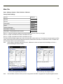
Main Tab
6-3
Continuous Scan Mode
COM1 Tab
6-5
Notification Tab
6-6
Data Options Tab
6-8
Enable Code ID
6-9
Buttons
6-10
Symbology Settings
6-11
Clear Button
6-11
Advanced Button
6-12
Processing Order
6-12
Enable, Min, Max
6-13
Strip Leading/Trailing Control
6-14
Barcode Data Match List
6-15
Barcode Data Match Edit Buttons
6-16
Match List Rules
6-17
Add Prefix/Suffix Control
6-18
Symbologies
viii
6-4
6-19
Custom AIM IDs
6-19
HHP Symbologies
6-20
OCR Symbology
6-28
OCR Template Examples
6-29
OCR Checksum Calculation
6-29
Ctrl Char Mapping
6-30
Translate All
6-31
Custom Identifiers
6-32
Control Code Replacement Examples
6-34
Bar Code Processing Examples
6-34
HHP Properties
6-36
Length Based Bar Code Stripping
6-38
Processing Tab
6-40
About Tab
6-41
Hat Encoding
6-42
Chapter 7 - Enhanced Launch Utility
7-1
Introduction
7-1
Registry Based Launch Items
7-1
Launch Startup options
7-3
Example
7-3
Script Based Launch Items
7-4
Enhanced Launch Utility Use
7-4
File Names
7-5
Command line structure
7-5
Comments
7-5
Commands Supported by Launch
7-6
Launch Error Messages
7-19
Example Script File
7-21
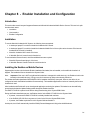
Chapter 8 - Enabler Installation and Configuration
8-1
Introduction
8-1
Installation
8-1
Installing the Enabler on Mobile Devices
8-1
Enabler Uninstall Process
8-2
Stop the Enabler Service
8-2
Update Monitoring Overview
8-2
Mobile Device Wireless and Network Settings
8-3
Preparing a Device for Remote Management
8-3
User Interface
8-4
Enabler Configuration
8-4
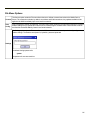
File Menu Options
8-5
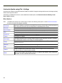
Avalanche Update using File > Settings
8-6
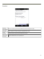
Menu Options
8-6
Connection
8-7
Execution
8-8
Server Contact
8-9
Data
8-10
Preferences
8-11
Taskbar
8-13
Scan Config
8-14
Display
8-15
Shortcuts
8-16
SaaS
8-17
Adapters
8-18
Status
8-21
ix
Exit
Using Remote Management
8-23
Using eXpress Scan
8-24
Step 1: Create Bar Codes
8-24
Step 2: Scan Bar Codes
8-24
Step 3: Process Completion
8-25
Chapter 9 - Wireless Network Configuration
9-1
Introduction
9-1
Important Notes
9-1
Summit Client Utility
9-2
Help
9-2
Summit Tray Icon
9-3
Using Windows Mobile Wireless Manager
9-4
Create a New Network Connection
9-4
Edit a Network Connection
9-6
Switch Control to SCU
9-6
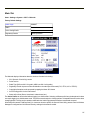
Main Tab
9-7
Auto Profile
9-8
Admin Login
9-9
Profile Tab
9-10
Buttons
9-11
Profile Parameters
9-12
Status Tab
9-14
Diags Tab
9-15
Global Tab
9-16
Custom Parameter Option
9-17
Global Parameters
9-18
Sign-On vs. Stored Credentials
9-22
How to: Use Stored Credentials
9-22
How to: Use Sign On Screen
9-23
Windows Certificate Store vs. Certs Path
9-24
User Certificates
9-24
Root CA Certificates
9-24
Configuring the Profile
x
8-22
9-26
No Security
9-27
WEP
9-28
LEAP
9-30
PEAP/MSCHAP
9-32
PEAP/GTC
9-35
WPA/LEAP
9-38
EAP-FAST
9-40
EAP-TLS
9-42
WPA PSK
9-45
Certificates
9-47
Generating a Root CA Certificate
9-48
Installing a Root CA Certificate
9-51
Generating a User Certificate
9-52
Exporting a User Certificate
Installing a User Certificate
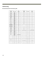
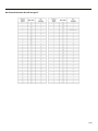
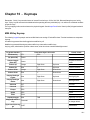
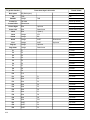
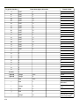
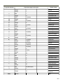
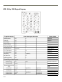
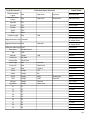
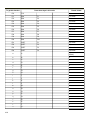
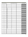
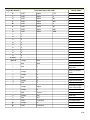
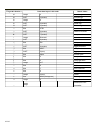
Chapter 10 - Keymaps
9-55
9-56
10-1
MX9 62-Key Keymap
10-1
MX9 62-Key 5250 Keypad Keymap
10-6
MX9 38-key Keymap
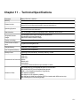
Chapter 11 - Technical Specifications
10-12
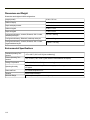
11-1
Dimensions and Weight
11-2
Environmental Specifications
11-2
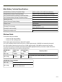
Main Battery Technical Specifications
11-3
Wireless Radio
11-3
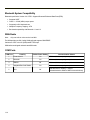
Bluetooth System Compatibility
11-4
WAN Radio
11-4
COM Ports
11-4
AC/DC Wall Adapter
11-5
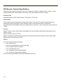
GPS Receiver Technical Specifications
11-6
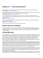
Chapter 12 - Technical Assistance
12-1
xi
xii
Chapter 1 - Introduction
The MX9 is a rugged handheld computer targeted for indoor and outdoor use. It is powered by a lightweight main battery that
can be removed and replaced without the need for special tools. MX9 wireless connectivity is secured by user-configured
encryption and authentication protocols.
The MX9 has an integrated keyboard, outdoor readable touch display, a tethered stylus, Microsoft® Windows® Mobile® 6.5
operating system, and many wireless connection options.
The keypad is available in a 62-key or 38-key configuration. The 62-key keypad is also available in an IBM 5250 configuration.
Bar code reader options are: an imager or laser scanner integrated in the MX9, or a handheld scanner tethered to the port at the
base of the MX9, Bluetooth mobile bar code imagers and scanners, or the Honeywell Bluetooth ring scanner / ring imager.
Wireless network connection can be accomplished using a Summit WLAN 802.11 radio, WWAN, and Bluetooth. Desk and
vehicle cradles, a trigger handle or handstrap, holsters with shoulder straps or belts, clear covers for cases and holsters,
Bluetooth scanners and printer, standard and low temperature batteries, and battery chargers are among the many accessories
available for the MX9.
l
If the MX9 has AppLock installed, please refer to AppLock for setup and processing information.
l
Wireless configuration and security parameters are described in detail in Wireless Network Configuration.
l
Review the Unlock process before locking the MX9.
Note:
Contact technical assistance for upgrade availability if your application or control panels are not the same as the
application or control panels presented in this guide.
About this Guide
This MX9 Reference Guide provides instruction for the system administrator to follow when configuring a MX9. This MX9
Reference Guide has been developed for a MX9 with a Microsoft® Windows® Mobile 6.5 Operating System.
1-1
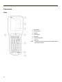
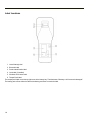
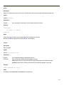
Components
Front
1. Microphone
2. Touch screen
3. Speaker
4. Scan buttons
5. Enter key
6. Scanner status LED
7. Power key
Note:
1-2
The above list is the same on the 38 key MX9. Special
keys are listed below.
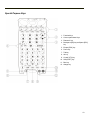
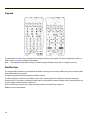
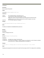
Special Purpose Keys
1. Function Keys
2. Cursor up and down Keys
3. Diamond 1 key
4. Backspace [BS] key and Space [SPC]
key
5. Escape [ESC] key
6. Power key
7. Tab key
8. Alt key
9. Control [CTL] key
10. Shift [SHFT] key
11. Blue key
12. Orange key
1-3
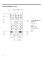
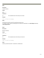
Special Purpose Keys - 38 Key
1. Diamond 1 key
2. Function keys
3. Tab / Space / Backspace keys
4. Diamond 2 key
5. Orange key
6. Escape [ESC] key
7. Alpha key
8. Control [CTRL] key
9. Shift [SHIFT] key
10. Cursor up and down keys
11. Blue key
12. Alt key
1-4
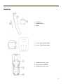
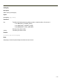
Top
Bar code reader aperture
Bottom
Input / Output Connector
Tethered boot cover not shown (covers I/O connector)
Back
Battery Bay
1. Battery Terminals
2. Battery Bay
3. Battery Bay Access Tab
1-5
Trigger Handle
Trigger handle attach points
1. Upper
2. Lower
1. Trigger
2. Tether attach point
Stylus storage bay in handle
1-6
Handstrap
1. Handstrap
2. Handstrap Base
3. Stylus
1. Attach - Upper Handstrap Base
2. Attach - Lower Handstrap Base
1. Handstrap connector, upper
2. Stylus holder on Handstrap
3. Handstrap connector, lower
1-7
Label Locations
1. Laser Warning Label
2. Bluetooth Label
3. Product Identification Label
4. Java Label (if installed)
5. Windows OS License Label
6. Tamper Proof Label
The tamper-proof label covers the top right screw in the battery bay. The label states "Warranty void if removed or damaged".
The battery pack will not deface the label as the battery pack does not touch the label.
1-8
External Power Supplies
External power supplies are available for the following:
l
any I/O cable with a power connector
l
desk cradle
l
vehicle cradle
l
car power adapter (CLA)
l
Battery multi-charger
The indoor power supplies (e.g., AC/DC Adapters) use IEC320-C 14 AC power connectors.
The car power adapter uses the cigarette lighter adapter (CLA) and is powered by the vehicle's automotive 12V battery. The
adapter power supply converts the input voltage into a voltage suitable to power the MX9 and charge the unit's internal backup
battery.
The vehicle mount cradle uses a 36V, 24-60V or 70-150V DC-DC power supply.
Note:
The MX9 and desk cradle and multi-charger use the same external power supply.
AC/DC 15V Power Supply
The MX9 receives AC/DC power from the AC/DC (15 VDC - 4 Amp - 60 Watt) Power Supply. The MX9 external power
connection is part of the serial cable assembly and the USB cable assembly.
The AC/DC Power Supply is connected to a wall outlet then to the power cable secured to the base of the MX9.
Note:
The Honeywell-approved AC Power Adapter is only intended for use in a 25°C (77°F) maximum ambient temperature
environment.
The indoor power supply has a IEC320-C 14 AC power connector.
When the power supply is receiving AC/DC power from the wall outlet, an LED on the power supply illuminates green. The
green LED indicates the power supply is ready for use.
This AC/DC power supply is designated for:
l
the MX9 I/O port multi-cables
l
the MX9 desktop cradle
l
the MX9 battery multi-charger
There are specific DC/DC power supply adapters for the MX9 vehicle cradle; do not use any other power supply with the
vehicle cradle.
1-9
Car Power Adapter
The MX9 Car Power Adapter is a self-contained unit. The cable has one and a half feet of coiled cord and one and a half feet of
straight cord. The coiled portion is on the end of the adapter. An LED on the adapter illuminates when the car power adapter is
receiving vehicle input power.
The cigarette lighter adapter contains a power supply which converts the vehicle’s nominal 12V to 15V, a voltage suitable to
power the MX9 and charge the MX9 battery.
One end consists of a plug compatible with a standard vehicle cigarette lighter adapter (CLA). The Car Power Adapter has a
standard size CLA plug that uses center positive (+12V) and sleeve ground. A replaceable fuse is provided on the input side.
The other end of the three foot cable connects to the MX9 36-pin I/O port. It has a security latch for stability when connected to
the Car Power Adapter cable.
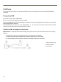
Replace CLA Fuse
Equipment needed: 5A fuse of the same size and amperage.
Remove the Cigarette Lighter Adapter (CLA) from the cigarette lighter outlet on the vehicle.
1. Disconnect the cable from the MX9.
2. Unscrew the tip of the CLA adapter end.
3. Replace the blown fuse with a fuse of the same rating and size.
4. Screw the tip back on to the CLA adapter end, replacing any previously removed parts in the order in which they were
removed.
Note:
Upon reassembling the cigarette lighter adapter with the new fuse, and plugging it into the cigarette lighter port on the
vehicle -- if the LED on the CLA does not illuminate green, there may be a problem with the vehicle power source.
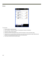
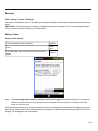
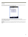
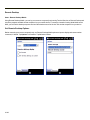
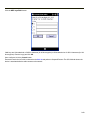
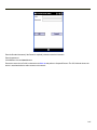
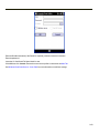
Locking the MX9
The MX9 can be locked manually by tapping Device unlocked on the Today screen. Care should be taken to not accidentally
tap this area of the Today screen.
Lock can be removed from the Today screen menu by selecting Start > Settings > Today > Items tab.
The MX9 can also be configured to Lock automatically after a defined period of inactivity. This setting is accessed on the Start
> Settings > Lock > Password tab. By default, this option is Disabled.
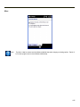
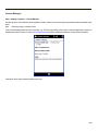
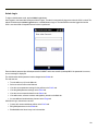
When the MX9 is locked, the Today screen displays Device locked by default. Tap Unlock at the lower part of the screen:
l
If there is no password or PIN set, tap Unlock on the next screen to unlock the MX9. The MX9 is returned to normal
operation.
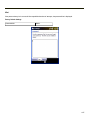
l
If there is a password or PIN set, enter the password/PIN and tap Unlock. If several unsuccessful attempts are made,
the MX9 may be configured to display a password hint.
The password and hint are configured by selecting Start > Settings > Lock > Password and Hint tabs.
1-10
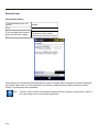
Reboot
When the Windows Mobile Today panel is displayed or an application begins, the power up (or reboot) sequence is complete.
Warmboot
A warmboot reboots the MX9 without erasing any registry data. Applications and data in RAM are preserved during a
warmboot.
All registry configurations are automatically preserved. Any applications stored as .CAB files in the System folder and
configured in the Registry to persist are reinstalled on boot up by the Launch utility.
Use the Registry control panel Warmboot button.
Note:
There may be slight delays while the wireless client connects to the network, re-authorization for voice-enabled
applications completes, Wavelink Avalanche management of the MX9 startup completes, or Bluetooth relationships
establish or re-establish.
Restart (or Cold Boot)
The Restart (or cold boot) function reboots the device and reloads RAM.
Use the Registry control panel Load Factory Defaults button to erase the registry and set the registry back to factory
defaults. No other clearing is available or necessary.
Note:
Because of the extreme nature of restart, Honeywell recommends using this command only as an emergency (or
when instructed to do so as part of a specific MX9 procedure).
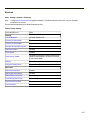
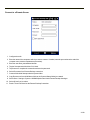
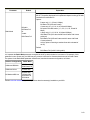
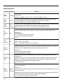
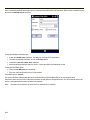
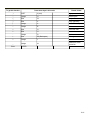
Startup Help
Can’t change the date/time or
adjust the volume.
AppLock is installed and may be running in User Mode on the MX9. AppLock user mode
restricts access to the control panels.
Touch screen is not accepting
stylus taps or needs
recalibration.
Press <Ctrl>+<Esc> to force the Start Menu to appear. Use the tab, backtab and cursor
keys to move the cursor from element to element.
MX9 seems to lockup as soon
as it is warm booted.
There may be slight delays while the wireless client connects to the network, authorization
for voice-enabled applications complete, and Bluetooth relationships establish or reestablish. When the desktop appears or an application begins, the MX9 is ready for use.
New MX9 main batteries don't
last more than a few hours.
New batteries must be fully charged prior to first use. Li-Ion batteries (like all batteries)
gradually lose their capacity over time (in a linear fashion) and never just stop working. This
is important to remember – the MX9 is always ‘on’ even when in the Suspend state and
draws a small amount of battery power at all times.
Keep losing ActiveSync
connection between my host
computer and the MX9.
When the MX9 enters Suspend Mode, all connections are closed to save battery power.
When the MX9 wakes up, if ActiveSync connection does not automatically re-establish,
disconnect the cable, wait 1-2 seconds and reconnect the cable.
1-11
1-12
Chapter 2 - Hardware
System Hardware
802.11 b/g and a/b/g Wireless Client
The MX9 has an 802.11x network card that supports diversity with two internal antennas. The CPU board does not allow hot
swapping the network card. Power management on the network card is set to static dynamic control.
WEP, WPA and LEAP are supported.
Central Processing Unit
The CPU is a 806 MHz Marvell PXA-320 CPU. The operating system is Microsoft Windows Mobile 6.5. The OS image is
stored in on-board flash memory.
The MX9 supports the following I/O components of the core logic:
l
One serial port (DTE) with appropriate power for a WAN radio
l
One serial port (DTE) for an integrated laser decoder with RI
l
USB 1.1 Host (capable) with power (5V @ 500mA)
l
One SSP port (capable, not implemented)
l
One SDIO port for I/O expansion (capable)
l
One SIM port for WAN
l
One serial port (DTE) for interface with GPS receiver chip
l
Non-decoding imager
System Memory
The MX9 supports 128 MB on-board RAM and 128 MB on-board Flash. Operating system and boot loader software image
update is supported via expansion card and remote management via radio.
Internal flash is used for boot loader code and system low-level diagnostics code. Bootloader code is validated at system
startup. The UUID is stored in the boot flash. A second copy of the bootloader code is stored on the internal SD Flash drive, so
that if a damaged bootloader is detected, it may be re-flashed correctly.
Internal SD Memory Card
The MX9 has one SD card interface for storage of operating system and program code, as well as persistent storage.
The internal SD flash card appears to the OS as a folder (Storage Card). This allows the contents to be manipulated via the
standard Windows interface.
2-1
Video Subsystem
The touch screen display supports QVGA and 16 bit color depth, and is readable indoors or outdoors even in direct sunlight.
The display is transflective active-matrix TFT and has an LED backlight.
A tethered stylus is included. The touch screen surface can be activated with the stylus or a gloved or bare finger.
The Cold Storage option includes a touch screen heater and a scan aperture heater to eliminate condensation. The heaters can
be enabled or disabled by the user. Once enabled, the heaters will turn on whenever the ambient temperature warrants, for
example, when moving into and out of freezers or refrigerated buildings.
Power Supply
The MX9 uses one of two batteries for operation. A Lithium-Ion (Li-Ion) standard battery has a 2400 mAh capacity. Low
temperature Lithium-Ion (Li-Ion) batteries have a 2100 mAh capacity.
Input/Output Connector
A single external connector at the base of the MX9 provides the following signals:
l
USB Host and USB Client
l
RS232 with support for powering a tethered device (e.g., scanner or imager)
l
Audio in and out for headset
l
Power input
l
Ethernet (only accessible when MX9 is secured in a cradle's docking bay)
The MX9 cables are designed to be securely connected to this port. This port is also used to connect the MX9 to the docking
bay connector in cradles.
A tethered protective cap is provided to cover the I/O connector when it is not in use.
Audio Support
All Microsoft-supplied audio codecs are included in the OS image. The hardware codecs, the input and output analog voice
circuitry and the system design are designed to support voice applications using a headset accessory cable.
2-2
Bluetooth
The MX9 contains Bluetooth version 2.0 with Enhanced Data Rate (EDR) up to 3.0 Mbit/s over the air. Bluetooth device
connection (or pairing) can occur at distances up to 32.8 ft (10 meters) Line of Sight. The wireless client retains network
connectivity while Bluetooth is active.
The user will not be able to select PIN authentication or encryption on connections to or from the MX9. However, the MX9
supports authentication requests from pairing devices. If a pairing device requests authentication or encryption, the MX9
displays a prompt for the PIN or passcode. Maximum encryption is 128 bit. Encryption is based on the length of the user
passcode.
Bluetooth devices can be paired and managed using the LXEZ Pairing control panel.
l
The LED on a mobile Bluetooth scanner illuminates during a scanning operation; the Scan LED on the MX9 does not
illuminate.
l
Bar code data captured by a mobile Bluetooth scanner is manipulated by the settings in the MX9 Data Collection panel.
l
Multiple beeps may be heard during a bar code scan using the mobile Bluetooth scanner; beeps from the mobile
Bluetooth scanner as the bar code data is accepted/rejected, and other beeps from the MX9 during final bar code data
manipulation.
Input/Output Port
A single external connector at the base of the MX9 provides the following signals:
l
USB Host and USB Client
l
RS232 with support for powering a tethered device (e.g., scanner or imager)
l
Audio in and out for headset
l
Power input
l
Ethernet (accessible when MX9 is secured in a powered cradle's docking bay)
The MX9 cables are designed to be securely connected to this port. This port is used to connect the MX9 to the docking bay
connector in cradles.
A tethered protective cap is provided to cover the external port when it is not in use.
2-3
Keypads
The MX9 keypad is either a 62-key full alphanumeric keypad or 38-key numeric-alpha. The 62 key keypad has an ANSI or a
5250 overlay. Keymaps are available for all keypads.
Note:
The keypad backlight default setting is to follow the display backlight setting until it is changed by the user.
Modifier Keys
The orange and blue modifier keys are located at the bottom of the keypad. The Orange and Blue keys do not need to be held
down while another key is pressed.
A modifier key pressed after itself toggles that modifier mode off.
A modifier keypress cancels the other modifier’s active state. Then the state of the modifier key that was pressed last
becomes active. For example, if the Orange modifier state is active (MX9 is currently in Orange mode), pressing the Blue key
cancels Orange mode and sets Blue mode active.
Once a modifier key is pressed, the modifier map state continues until another key is pressed.
Modifier keys do not auto-repeat.
2-4
Expansion Slots
l
Summit radio card
l
SIMM card
l
SD card
The expansion slots in the MX9 are accessible via the hatch. The hatch can be opened using a standard size screwdriver.
When the hatch is opened, the MX9 automatically shuts down.
SD card configurations in 512MB, 1GB and 4GB are available from Honeywell.
Note:
For best results save your changes then perform an orderly shutdown to preserve RAM contents before opening the
hatch.
Power Key Functions
The Power key is located at the bottom left of the keypad. The Power On/Off key is a momentary contact. Function is as
follows:
When the MX9 is in ...
Pressing the Power key ...
Off mode
boots the unit and sets it to the On mode
On mode
sets the unit in Suspend mode
Suspend mode
sets the unit in On mode
Critical Suspend mode
has no effect
Backlight off mode
sets the unit in Suspend mode
2-5
Status LEDs
Several LEDs are located on the front of the MX9 above the integrated speaker. They are:
l
System Status (SYS) LED indicates power management status.
l
Battery Charging Status (BATT) LED indicates main battery charging status.
l
Alpha Mode Status (ALPHA) LED applies to the 38-key keypad only.
l
Bluetooth Status LED applies to Bluetooth client functions.
System Status LED
Blinking Red
Battery power fail; critical suspend
Solid Red
Main battery low
Yellow / Amber
Initial few seconds when Power key is pressed
Battery Charging Status LED
Off
No battery, no AC power, battery pack not plugged in or no AC power applied
Flashing Red
Fault, battery pack fault or failure
Yellow / Amber
Standby, battery pack temperature out of range
Red
Charging, battery pack charging (icon on touch screen)
Green
Charged, battery pack fully charged. Connected to external power.
Alpha mode Status LED
l
Green when in alpha mode, 38-key keypad only.
Bluetooth Status LED
Blinking slowly
Bluetooth is active but not connected to a device.
Blinking medium
Bluetooth is paired and connected to a device.
Blinking fast
Bluetooth is discovering other Bluetooth devices.
Unlit
Bluetooth hardware has been turned off or does not exist in the MX9.
2-6
Scanner Status LED
The integrated scanner, and imager, Scan Status LED is centered below the MX9 keypad, next to the Power button.
l
Steady green indicates a good scan
l
Steady red indicates a scan is in progress
l
Steady yellow/amber indicates parameter changes are being written to the integrated scanner/imager engine
The Scan Status LED illuminates when a Scan button on the MX9 is depressed (scan in progress), or the trigger on the
attached handle is pressed (scan in progress), or when the scanner/imager engine parameters have been changed and the
changes are being saved (writing to scan engine). While the changes are being saved, the scanner/imager is inoperable.
l
The MX9Scan Status LED does not illuminate when the Scan button is pressed on a scanner cabled to the MX9 or
cabled to an MX9 cradle communication port. The Scan LED on the cabled scanner/imager illuminates.
l
The MX9 Scan Status LED does not illuminate when the Scan button is pressed on a wireless Bluetooth mobile
scanner paired with the MX9. The Scan LED on the wireless Bluetooth mobile scanner/imager illuminates.
Note:
A scanned bar code can be accepted as a good scan or a bad scan by the MX9 bar code decoder (as configured). The
appropriate audible or tactile indicator is activated.
Note:
The result of the host processing (as configured) of the good scan bar code data can indicate either accept or reject. If
rejected, a bad scan indicator is activated if the host process has been configured to indicate audible or tactile accept
or reject.
Cold Storage
When the MX9 has been configured as a cold storage or low temperature device, it has a snowflake decal between the touch
screen and the keypad.
The MX9, with its special low temperature battery and condensation controlling heaters is designed specifically for use in
freezers and refrigerator environments including transitioning between the two.
Heating Elements
Heating elements activate when ambient temperature drops below 0°C (32°F). Honeywell recommends using the stylus when
performing screen touch functions on the display when the temperature drops below freezing.
There may be some condensation as the MX9 moves in and out of cold storage areas. The condensation on the touch screen
and the scan aperture quickly dissipates.
Although no user interaction is required to enable the heating elements, the automatically controlled heating elements can be
enabled and disabled using the Heaters tab in the Peripherals panel.
2-7
Vibrate Indicator
The MX9 has a vibration motor.
It is user-configurable to vibrate on a good scan, bad scan, or via an API call. The vibrations from this motor are detectable
under the handstrap at the rear of non-handle units or through the trigger handle when a trigger handle is installed.
Three vibration duration settings are provided for both good and bad scan. The settings can be assigned on the Start > Settings
> System > Data Collection > Notification tab. The default setting for both good scan and bad scan is Off.
Scanners and Imagers
Note:
The maximum number of communication ports from which the Data Collection Wedge can simultaneously support
input is three.
Integrated Bar Code Decoders
The MX9 may have any of the following bar code reader built in (integrated) and protected by the hatch:
l
Symbol SE955 short range laser scanner engine (bar code decoding only)
l
Symbol SE1524 Lorax laser scanner engine (bar code decoding only)
l
Hand Held Products 5300SF laser imager engine (non-decoding)
A scan aperture heater is implemented for low temperature environments.
Tethered Bar Code Decoders
The external serial port at the base of the MX9 is used to connect (via serial tether) tethered laser scanners as needed.
Bluetooth Client Bar Code Decoders
The Bluetooth Module in the MX9 can accept data from paired Bluetooth bar code readers.
GPS Module
The default setting for GPS is Off.
GPS (Global Positioning System) is a U.S. space-based radio navigation system that provides reliable positioning, navigation,
and timing services on a continuous basis. The primary function of the embedded GPS module is to provide worldwide location
to applications which are running on the MX9.
GPS presence is displayed on the Peripherals panel. Using the GPS tab, GPS power can be toggled on or off only when a GPS
is installed.
See Also: "Technical Specifications"
2-8
Chapter 3 - Power
Power Modes
On Mode
The Display
When the display is On:
l
the keypad, touch screen and all peripherals function normally
l
the display backlight and keypad backlight are on until the Backlight timer expires
The MX9
After a new MX9 has been received, a charged main battery inserted, and the Power key tapped, the MX9 is always On until
both batteries are drained completely of power.
When the main battery and Super-cap battery are drained completely, the unit is in the Off mode. The unit transitions from the
Off mode to the On mode when a charged main battery is inserted or external power is applied and the Power key is pressed.
Suspend Mode
The Suspend mode is entered when the unit is inactive for a predetermined period of time or the user taps the Power key. MX9
Suspend timers are set using Start > Settings > Power > Advanced tab.
Wake-up Events - all configurable via Power Management API call:
l
Any key on the keypad
l
Stylus touch on the touch screen
l
Handle trigger press
l
Connecting to AC adapter
l
Power button tap
l
USB connection
l
COM port control CTS
l
Real time clock
l
Bluetooth device reconnect / disconnect message
When the MX9 wakes up, the Display Backlight and the Power Off timers begin the countdown again. When any one of the
above events occurs prior to the Power Off timer expiring, the timer starts the countdown again. The MX9 needs to be placed
in Suspend mode before hotswapping the main battery.
Off Mode
The unit is in Off Mode when the main battery and the Super-cap battery are depleted. Insert a fully charged main battery and
press the Power key to turn the MX9 On.
3-1
Batteries
The MX9 is designed to work with a replaceable 2400 mAh Lithium-Ion (Li-Ion) battery pack from Honeywell. Under normal
conditions it should last approximately eight hours before requiring a recharge.
MX9 low temperature 2100 mAh Lithium-Ion (Li-Ion) batteries (designed for freezer environments and with a blue label) have an
average use time of 4 hours before requiring a recharge.
During very heavy scanning or wireless transmitter use, the operating time of the battery may be less.
HazLoc versions of the MX9 require a screwdriver to remove the plate covering the battery release mechanism.
Note:
New main battery packs must be charged prior to use. This process takes up to four hours in an MX9 Battery Charger
and six hours when the MX9 is connected to external power.
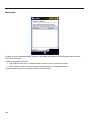
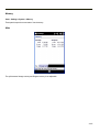
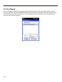
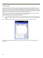
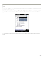
Checking Battery Status
Tap the Start > Settings > System > Battery. Battery voltage level, status and power remaining is displayed.
Main Battery Pack
The main battery pack has a rugged plastic enclosure that is designed to withstand the ordinary rigors of an industrial
environment. Exercise care when transporting the battery pack making sure it does not come in contact with excessive heat or
any power source other than the MX9 Multi-Charger or the MX9 unit.
When the main battery pack is properly installed in the unit it provides up to eight hours of operation depending upon use and
accessories installed. The battery pack is resistant to impact damage and falls of up to four feet to a concrete surface. Under
normal conditions it should last approximately eight hours before requiring a recharge. The more you use the scanner or the
wireless transmitter, the shorter the time required between battery recharges.
When the MX9 is docked in a powered cradle, the battery in the MX9 is recharged through the cradle connector in the
docking bay. An extra Li-Ion battery pack can be recharged in a powered desktop cradle. The battery is fully recharged in a
powered cradle in less than 4 hours. The MX9 can be Off, in use or in Suspend Mode while the battery is recharging.
Note:
3-2
When the main battery and internal battery are fully depleted, the MX9 turns off. The operating system reverts to the
last saved registry settings when a fully powered battery is inserted and the MX9 is turned on.
Battery Hotswapping
Important: When the internal battery power is Low or Very Low (Start > Settings > Power) connect the AC adapter to the MX9
before replacing the main battery pack.
When the main battery power level is low, the MX9 will signal the user with the low battery warning indicator (the Status LED
remains a steady red) that continues until the main battery is replaced, the battery completely depletes, or external power is
applied to the MX9 using an AC Adapter.
You can replace the main battery by first placing the MX9 in Suspend Mode then removing the discharged main battery and
installing a charged main battery within a five minute time limit (or before the Super-cap internal battery depletes). When the
main battery is removed the MX9 enters Critical Suspend state; the MX9 remains in Suspend mode, the display is turned off
and the internal battery continues to power the unit for at least five minutes.
Though data is retained, the MX9 cannot be used until a charged main battery is installed. After installing the new battery,
press the Power key. Full operational recovery from Suspend can take several seconds while the client is reestablishing a
network link. If the internal battery depletes before a fully charged main battery can be inserted, the MX9 will turn Off.
Low Battery Warning
It is recommended that the main battery pack be removed and replaced when its energy depletes. When the main battery Low
Battery Warning appears (the Status LED remains a steady red) perform an orderly shut down, minimizing the operation of any
installed devices and insuring any information is saved that should be saved.
Super-cap Internal Battery
The MX9 has an internal battery that is designed to provide limited-duration electrical power in the event of main battery failure.
The energy needed to maintain the internal battery near full charge at all times is drawn from the MX9 main battery. It takes 5
minutes or less to fully charge the internal battery. The duration of internal battery life is dependent upon operation of the MX9,
its features and any operating applications. The internal battery has a minimum service life of two years. The Super-cap
internal battery is replaced by Honeywell.
Handling Batteries Safely
l
Never dispose of a battery in a fire. This may cause an explosion.
l
Do not replace individual cells in a battery pack.
l
Do not attempt to pry open the battery pack shell.
l
Be careful when handling any battery. If a battery is broken or shows signs of leakage do not attempt to charge it.
Dispose of it using proper procedures.
Caution
Nickel-based cells contain a chemical solution which burns skin, eyes, etc. Leakage from cells is the only possible way for
such exposure to occur. In this event, rinse the affected area thoroughly with water. If the solution contacts the eyes, get
immediate medical attention.
NiMH and Li-Ion batteries are capable of delivering high currents when accidentally shorted. Accidental shorting can occur
when contact is made with jewelry, metal surfaces, conductive tools, etc., making the objects very hot. Never place a battery
in a pocket or case with keys, coins, or other metal objects.
3-3
3-4
Chapter 4 - Software
Introduction - Operating System
This MX9 Reference Guide has been developed for a MX9 with a Windows Mobile® operating system.
There are several different aspects to the setup and configuration of the MX9. Many of the setup and configuration settings are
dependent upon the optional features such as hardware and software installed on the mobile device. The examples found in
this section are to be used as examples only, because the configuration of your specific MX9 may vary. The following sections
provide a general reference for the configuration of the MX9 and some of its optional features.
Note:
For best results frequently charge the MX9 battery using an external power source to ensure continuous charging of
the internal Super-cap battery.
Windows Mobile
Note:
For general use instruction, please refer to commercially available Windows Mobile user guides or the Windows
Mobile on-line Help application installed with the MX9
This section’s contents assumes the system administrator is familiar with Microsoft Windows options and capabilities loaded
on most standard Windows 2000 or later desktop computers.
Therefore, the sections that follow describe only those Windows capabilities that are unique to the MX9 and its Windows
Mobile environment.
Notes
Based on your installed software version and hardware options, your setup may not be exactly the same as those that are
described in this guide. Contact technical assistance for information on the latest upgrades for your MX9.
Installed Software
Note:
Some standard Windows options require an external modem connection. Modems are not available.
When you order an MX9 you receive the software files required by the separate programs needed for operation and wireless
client communication. The files are stored in folders in the mobile device.
This section lists the contents of the folders and the general function of the files. Files installed in each MX9 are specific to the
intended function of the MX9.
Files installed in Windows mobile devices that are configured for a wireless environment usually contain a radio specific driver
– the driver for the radio is specific to the manufacturer of the radio installed in the wireless host environment and are not
interchangeable.
4-1
Software Load
The software loaded on the MX9 computer consists of Windows Mobile Operating System, hardware-specific OEM Adaptation
Layer, device drivers, Internet Explorer for Windows Mobile browser and MX9-specific utilities. The software supported by the
MX9 is summarized below:
Operating System
Full Operating System License: Includes all operating system components, including Windows Mobile kernel, file system,
communications, connectivity (for remote APIs), device drivers, events and messaging, graphics, keyboard and touch screen
input, window management, and common controls.
Network and Device Drivers
Bluetooth (Option)
AppLock (Option)
RFTerm (VT220, TN5250, TN3270) Terminal Emulation (Option)
Honeywell API Routines
Note:
Contact technical assistance to get access to updated software releases.
Software Backup
Application programs and data that are normally RAM resident are backed up via ActiveSync.
Version Control
Version numbers are applied to the boot loader and the OS image independently. The version information stored consists of the
build number, plus the date and time of compile (in lieu of a build number). These version numbers are stored in non-volatile
storage, where the user cannot inadvertently modify them. A Settings panel and API are provided so the user can reference the
version numbers for support purposes.
The MX9 has a unique 128-bit ID code as required by the Windows Mobile specification. This ID number is generated by the
boot loader. This ID code is available in the About Info settings panel, and via a Win32 standard API.
In addition, an API is provided to return a standard copyright string, so that applications may reference the string for licensing
purposes.
4-2
Boot Loader
The MX9 supports a proprietary boot loader. It is the responsibility of the boot loader to:
l
Initialize all system hardware
l
Initiate OS startup
l
Handle wakeup from system suspend, loading saved state
The MX9 starts the OS every time during warm boot or restart.
Startup Folders and Launch Sequences
The MX9 operating system uses two startup folders:
l
User applications placed in the Windows\Startup folder automatically run during a warm boot. They are deleted upon a
restart.
l
User applications placed in the System\Startup folder automatically run during a warm boot, after a restart and after
restoring factory defaults.
Installing Applications
Applications can be installed on the MX9 from CAB files.
CAB files are (re)installed after a cold boot, but not after a suspend/resume since the OS was not reset and the CAB files are
still in use.
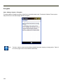
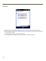
An unsigned executable (CAB or package file) prompts the user when executed:
The program is from an unknown publisher. Running it can possibly harm your device. Do you want to continue?
If you trust the program, tap Yes. Otherwise tap No.
CAB files can be copied to the MX9 via ActiveSync or they can be installed from the Flash card.
Contact technical assistance or your system administrator for more information on CAB files available for the MX9.
Software Development
The CE API Programming Guide documents API calls for the MX9. It is intended as an addition to the standard Microsoft
Windows Mobile API documentation.
A Software Developers Kit (SDK) and additional information about software development can be found on the Developer
Portal. Contact technical assistance for more information.
4-3
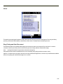
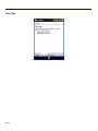
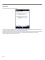
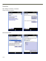
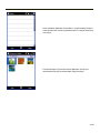
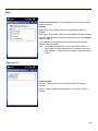
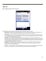
Today Screen
For general use instruction, please refer to commercially available Windows Mobile user guides or the Windows Mobile on-line
Help on the MX9.
Note:
Whenever possible, use the AC power adapter with the MX9 to conserve the main battery and to ensure the internal
battery is charged.
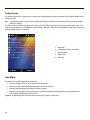
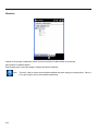
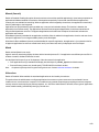
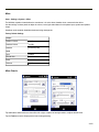
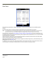
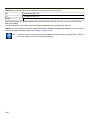
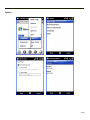
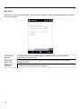
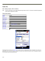
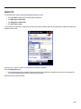
The main screen for the MX9 is known as the Today screen. The Today screen shows various options and status icons. The
Today screen appearance is configurable by selecting Start > Settings > Today. Both the appearance of the Today screen and
the items displayed may be configured.
1. Start menu
2. Configurable Today screen listing
3. Notification Bar
4. Status icons
5. Soft Keys
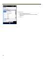
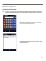
Start Menu
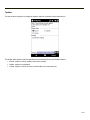
The Start menu consists of applications and folders.
l
Selecting an application from the menu starts that application.
l
Selecting a folder opens a window displaying the contents of the folder.
l
Selecting Settings displays the Settings panels by category.
l
Selecting Help displays context sensitive help. The contents displayed in the help window vary depending on the
screen displayed before Help was accessed.
Programs not appearing on the Start menu can be accessed by using the File Explorer.
4-4
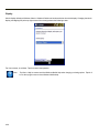
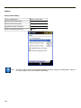
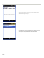
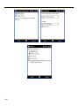
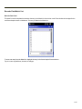
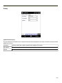
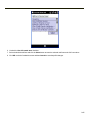
Configurable Today Screen Listing
The items displayed in the Today screen listing can be configured from Start > Settings > Today > Items.
For more information, please see Today settings later in this section.
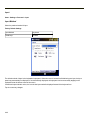
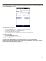
Date
When the Date is enabled to display on the Today screen, the date is displayed on the left side of the screen and the time is
displayed on the right side. If there are any alarms set, a bell icon is displayed under the current time.
For more information, please see the Clock & Alarm settings section.
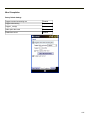
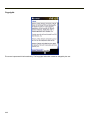
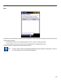
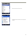
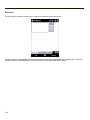
Device Unlocked / Device Locked
When the MX9 is unlocked, tapping on Device unlocked locks the MX9.
When the MX9 is locked, tapping on Unlock at the bottom of the screen unlocks the MX9. Depending on the settings, a
password may be required. The MX9 can also be configured to lock after a period of inactivity. For more information, please
see the Lock settings.
4-5
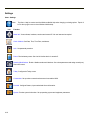
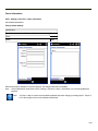
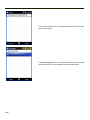
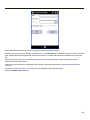
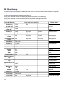
Notification Bar
The Notification Bar is displayed at the top of the Today screen. The notification bar remains visible even when other screens
are selected, though the icons displayed may vary.
When the Notification bar is displayed on other screens there may be an X (close the current screen/program) or an ok (accept
the current input and close the screen).
Category Icon
Meaning
Network
The Windows Mobile Wireless Manager is managing the wireless connection and the MX9 is connected to
a wireless network.
Network
A wireless manager is managing the wireless connection.
Network
A wireless manager is managing the wireless connection and has detected one or more wireless networks
in range.
Network
A wireless manager is managing the wireless connection and has not detected a wireless network in range.
Network
The Wireless Wide Area Network is connected to a cellular network.
Volume
The speaker is on.
Volume
The speaker is off.
Volume
Vibrate is on.
Power
The MX9 is connected to external power.
Power
The MX9 is operating on battery power. The strength of the battery is indicated by the number of bars displayed: 0 (low battery) to 4 (fully charged battery).
4-6
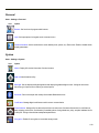
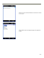
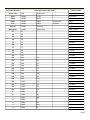
Status Icons
Additional icons may be displayed at the lower edge of the Today screen.
Note:
Summit signal strength icons are displayed only when the Summit Client Utility is controlling the radio.
Bluetooth module is connected to one or more of the targeted Bluetooth device(s).
MX9 is not connected to any Bluetooth device.
MX9 is ready to connect with any Bluetooth device.
MX9 is out of range of all paired Bluetooth device(s). Connection is inactive.
Summit radio is not currently associated or authenticated to an Access Point.
The signal strength for the currently associated/authenticated Access Point is less than -90 dBm
The signal strength for the currently associated/authenticated Access Point is -71 dBm to -90 dBm
The signal strength for the currently associated/authenticated Access Point is -51 dBm to -70 dBm
The signal strength for the currently associated/authenticated Access Point is greater than -50 dBm
More information on Bluetooth can be found in the Bluetooth settings section.
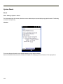
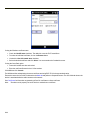
Soft Keys
Soft Keys are displayed at the bottom of the Today screen. The keys displayed vary by the active screen/application.
The soft keys generally provide menus for the selected application. By default, on the Today screen, the left Soft Key
(Calendar) can also be accessed by pressing F3 and the right Soft Key (Contacts) can be accessed by pressing F4. The Soft
Key events can be changed by selecting Start > Settings > Personal > Buttons.
4-7
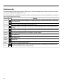
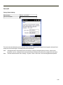
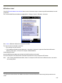
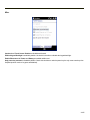
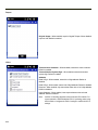
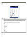
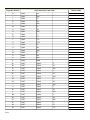
Start Menu Options
The following options represent the factory default program installation. Your system may be different based on the
software and hardware options purchased.
Use the up and down arrow keys on the MX9 to quickly scroll through the icons,
or,
using screen touch gestures, brush the window up or down with a finger or the stylus.
Icon
Function
Basic ActiveSync configuration, including synchronization with an Exchange server.
Avalanche. Mobile devices have the Avalanche Enabler installation files loaded, but not installed, on the mobile
device when it is shipped.
Calculator
Calendar/date book application. Can be synchronized with PC Outlook calendar using ActiveSync.
Contacts. Address book application. Can be synchronized with PC Outlook address book using ActiveSync.
Email application. Can be synchronized with PC Outlook email using ActiveSync or it can synchronize with an
Exchange server.
File Explorer. Displays a structured picture of files on the system.
Help. Access Windows Mobile help system on the MX9. Options to search using Windows Live Search are
available.
Internet Explorer. Access web pages on the Internet.
Notes. Notebook application. Select Menu > View Recording Toolbar to create an audio note. Can be
synchronized with PC Outlook notes using ActiveSync.
Office Mobile. Access to Excel, PowerPoint, Word and OneNote. Compatible with Microsoft Office 2007.
4-8
Icon
Function
Pictures and Video. Picture/video viewer application. Can be synchronized with PC My Documents folder using
ActiveSync.
Remote Desktop (Auto). A shortcut to Remote Desktop Mobile with Connect activated.
Remote Desktop Mobile. Display remote desktop. Setup for computer, user name, password and domain
required. Use Options to setup connected options for the remote desktop.
Settings. Access to system level setup programs: Connections, Personal, and System among others.
Task Manager. View and cancel running tasks.
Tasks. Task list application. Can be synchronized with PC Outlook task list using ActiveSync.
Today. Configure the appearance and the items to display on the Today screen.
Windows Live. Sign in to Microsoft Windows Live online service. Internet access required.
Windows Media. Audio visual management program. Not supported on the MX9.
4-9
Office Mobile
Icon
Function
Excel Mobile. Spreadsheets can be edited, data can be sorted, formatting and changes are preserved.
PowerPoint Mobile. Open, view and edit slides in landscape or portrait format. Zoom and GoTo features enabled.
Word Mobile. Open, view, edit documents. Formats are saved. Spelling checker, cut and paste are available,
undo and redo commands.
OneNote Mobile. Open, view, edit text-only notes.
Note:
4-10
Tap Start > Help for context sensitive Windows Mobile Help when changing or viewing options. Tap the X
icon in the top right corner to close Windows Mobile Help.
Installed Programs
Additional information on installed programs is listed below.
Internet Explorer Mobile
Start > Internet Explorer Mobile
This browser is a subset of and is compatible with IE 6.0 (as might be installed on a desktop PC). Internet Explorer Mobile has
two viewing modes: Mobile mode and Desktop mode. Mobile mode is used for web sites which specifically support mobile
phone formatted web pages. Desktop mode displays a small portion of the web site, and a small window which allows the view
to move around within the larger web page window (or move with gestures).
For information on general configuration options, please see the Windows Mobile help system on the MX9 or other
commercially available Internet Explorer configuration resources. Tap the IE Menu soft key (on the lower right) and select
Tools > Options to set up the default home page, view browsing history, setup privacy and security, preferred language, and
Other options.
If an Internet Explorer web page is larger than the MX9 screen can display at one time, use touch screen gestures for horizontal
and vertical scrolling.
For information on the version of Internet Explorer loaded on the MX9, tap the Favorites soft key and select About Internet
Explorer.
Office Mobile Applications
Start > Office Mobile
Office 2003 and Office 2007 formats are supported, though these are subset applications so not all objects may appear as
expected.
ActiveSync handles all file format conversions for these files transferred between the MX9 and the host PC.
ActiveSync
Start > ActiveSync
ActiveSync can be setup to synchronize with an Exchange server. Contact your system administrator for configuration
information.
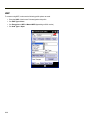
AppLock (Option)
Start > Settings > System > Administration
The AppLock program is accessed by the user or the AppLock Administrator at boot up or upon completion of a cold boot. Set
parameters using the Administration option in the Settings Panel.
4-11
Summit
SCU (Summit Client Utility)
Start > Settings > System > Summit
Summit automatically installs and runs after every cold boot. Use this option to set up radio client profiles. See Wireless
Network Configuration for instruction.
Certs
Start > Settings > System > Summit > Certs
The Certs option displays a readme file containing details on how the Summit Configuration Utility (SCU) handles certificates
for WPA authentication.
See Wireless Network Configuration for instructions for acquiring CA and user certificate files.
Windows Media
Start > Windows Media
Codecs are included for WMA, WMV, MP3 and WAV files.
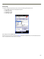
Bluetooth (Option)
Start > Settings > System > Bluetooth
Only installed on a Bluetooth equipped MX9. The System Administrator can Discover and Pair targeted Bluetooth devices for
each MX9. The System Administrator can enable / disable Bluetooth settings and assign a Computer Friendly Name for each
MX9. Bluetooth can be accessed by tapping Start > Settings > System > Bluetooth, or by tapping the Bluetooth icon on the
Today screen.
4-12
RFTerm (Option)
Start > RFTerm
Factory installed when ordered. The application can be accessed by tapping Start > RFTerm.
Refer to the RFTerm Reference Guide for complete information and instruction. WAV files added by the user should be stored
in System\LXE\RFTerm\Sounds.
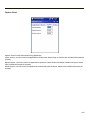
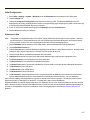
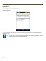
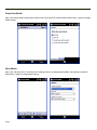
Status Popup
Start > Settings > System > MX9 Options
The Status Popup provides real time information on several status icons when a specified keypress occurs.
To use the Status Popup, first map a key to the status window. Use the Buttons panel (Start > Settings > Personal > Buttons)
to assign a key to Admin Statpop (for the Admin Popup) and StatPopup (for the User Popup). For best results use a Diamond
key for the popup. If a Function key is used, that Function key is not available to other applications such as RFTerm.
Use the MX9 Options panel (Start > Settings > System > Options) to configure other parameters including:
l
Dismiss Status Popup on 5 second timeout
l
Information to include in Admin or User Status Popup.
The Status Popup can be dismissed by the expiration of the timeout (if enabled), tapping the status window or pressing the key
assigned to the popup.
For more information, please refer to the Buttons and MX9 Options settings.
4-13
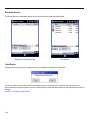
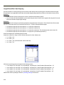
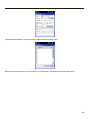
HSMConnect
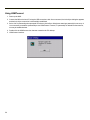
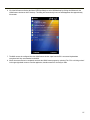
HSMConnect allows a user with an ActiveSync connection between a PC and the MX9 to display the MX9 screen on the host
PC. Any keystrokes on the host PC are passed to the MX9 as if they were keystrokes on the MX9 keypad.
HSMConnect for the MX9 is available on the Getting Started Disc.
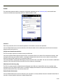
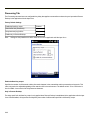
GrabTime
GrabTime is a utility to synchronize the MX9 with a world-wide time server. GrabTime can be started as a service by setting it
in the Launch option (see the following section for details on Launch).
Synchronize with a local time server
l
Use ActiveSync to copy GrabTime.ini from the My Device > Windows folder on the MX9 to the host PC.
l
Edit GrabTime.ini (on the host PC) to add the local time server’s domain name to the beginning of the list of servers. You
can then optionally delete the remainder of the list.
l
Copy the modified GrabTime.ini to the My Device > Windows folder on the MX9.
Enhanced Launch
Launch is a utility that runs automatically at startup. A partial list of Enhanced Launch functions includes:
l
Launch a .CAB file
l
Run an .EXE or .BAT file
l
Process a .REG file
l
Manipulate files and directories
l
Modify registry keys
l
Perform conditional operations
Note:
The Enhanced Launch utility does not interact with or affect the AppLock Launch command.
For a complete list of Launch functions including commands and command structure, please see Launch Utility.
4-14
MX9 OS Upgrade
Introduction
Depending on the size of the operating system, the total time required for a successful upgrade may require several minutes.
The OS upgrade files are unique to your MX9 physical configuration and date of manufacture. OS upgrade files designed for
one device configuration should not be used on a different device configuration.
During the upgrade process all settings revert to factory defaults. Parameters will need to be changed from factory defaults to
your preferred values at the conclusion of the upgrade process.
OS and Language Options
The MX9 running Windows Mobile must be returned to the manufacturer, Honeywell, if the device is to be re-imaged with any
other Windows operating system (for example, Windows CE).
Preparation
l
Please Contact technical assistance to get the OS upgrade files from Honeywell.
l
Put the upgrade files on a PC with ActiveSync capability.
l
Use ActiveSync to backup MX9 user files and store them elsewhere before beginning an upgrade on the MX9.
l
Copy the upgrade files from the PC to a SD card.
l
SD card removal/installation should be performed on a clean, well-lit surface.
l
Always perform MX9 updates when it has a fully charged main battery and/or a dependable external power source
connected to the MX9.
4-15
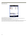
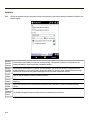
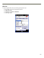
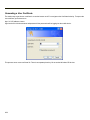
Accessing the SD Card Slot
Tools required: standard size Phillips screwdriver (customer supplied).
The expansion slots in the MX9 are accessible via the hatch. The hatch can be opened using a standard size screwdriver.
When the hatch is opened, the MX9 automatically shuts down. It is good practice to save any changes then perform an orderly
shutdown to preserve RAM contents before opening the hatch.
When the hatch is open during this procedure, do not remove any cables or allow them to kink.
1. Summit radio card is located in the back half of the MX9 assembly.
2. SIMM card is located in the front half of the MX9 assembly.
3. SD card is located in the front half of the MX9 assembly.
4-16
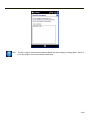
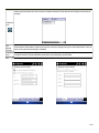
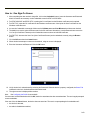
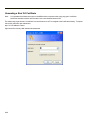
Procedure
While the hatch is open slide the installed SD card out of the slot. The MX9 may not have a SD card in the slot because the OS
is in flash.
1. Place the card with the new image files on it into the SD slot. The label on the SD card should be facing up.
2. Close the hatch. When the hatch is being closed, carefully move cables and wires back into the cavity before securing
the hatch. Before securing the hatch completely, examine the seam between the front and back half of the MX9. If the
gasket is off-center, loosen the screws a little, adjust the gasket and re-tighten the screws.
3. Press the Power button to turn the MX9 on.
4. The bootloader file in My Device > Storage Card automatically launches.
5. Important: If a failure occurs during the update, DO NOT RESTART (or coldboot). Follow the instructions on the screen
to Exit the update utility then restart the update utility.
6. Do not touch the device until the install/update is complete.
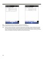
When the process is finished, remove the SD card following the instructions in Accessing the SD Card Slot. When finished,
press the Power button.
Check the OS update version by viewing the About or About Info panels.
Note:
If the application displays “Update OS Image Failed” or “Update Boot Loader Image Failed”, do not Restart the system
manually. Perform a warm boot, then try the upgrade again. Restarting will cause a system crash, since there is no
valid image in the MX9 system.
Battery State and OS Upgrade
A fully charged main battery must be installed in the MX9 prior to upgrading the operating system. A prompt may appear when
the battery reaches Critical Low that informs the user there is not enough power in the main battery to perform the upgrade.
The operating system will not be able to execute the OS upgrade when the battery level is too low (25% or less), as there is a
high risk that the power remaining in the battery expires when executing the upgrade and the MX9 will be left in an inoperable
state.
When main battery power level is too low, connect external power to the MX9 before performing the upgrade procedure. Do not
disconnect external power before the upgrade process is complete.
Upgrade Help
The powered device won't boot up after the upgrade is finished.
Contact technical assistance for re-imaging options if the MX9 won't boot up after the upgrade is finished.
The MX9 running Windows Mobile must be returned to Honeywell if the device is to be re-imaged with any other Windows
operating system (for example, Windows CE 6).
Warning: Opening the device e.g., removing endcaps or access panels, etc. could void the user's authority to
operate this equipment.
4-17
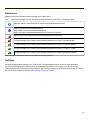
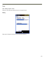
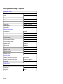
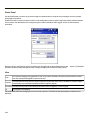
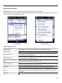
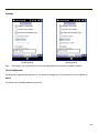
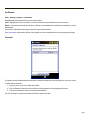
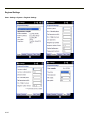
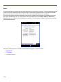
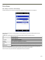
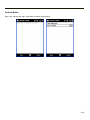
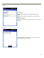
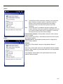
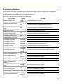
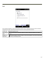
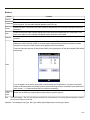
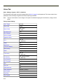
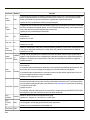
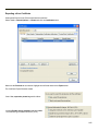
Settings
Start > Settings
Note:
Icon
Tap Start > Help for context sensitive Windows Mobile Help when changing or viewing options. Tap the X
icon in the top right corner to close Windows Mobile Help.
Function
About Info. View software, hardware, versions and network IP. No user intervention required.
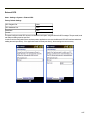
Clock & Alarms. Set Date, Time, Time Zone, and alarms.
Lock. Set password protection.
Power. Review battery status. Set time limit before device is turned off.
Sounds & Notifications. Enable / disable sounds and vibrations. Set volume parameters and assign sound (wav)
files to OS events.
Today. Configure the Today screen.
Connections. Set up various connections between a host and the MX9.
Personal. Configure Buttons, Input method and Owner information.
System. Review system information. Set up operating system and equipment parameters.
4-18
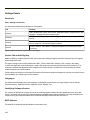
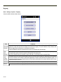
Personal
Start > Settings > Personal
Icon
Option
Buttons. Set functions of programmable buttons.
Input. Set input options for keypad, touch screen and voice.
Owner Information. Set the mobile device owner details (name, phone, etc). Enter notes. Enable / disable Owner
display parameters.
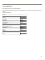
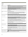
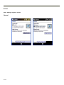
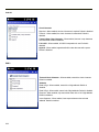
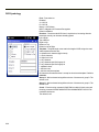
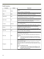
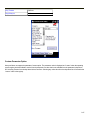
System
Start > Settings > System
Icon
Option
About. Display OS version information. Set device name.
AppLock Administration utility.
Backlight. Set the display backlight brightness and display/keypad backlight timeout. Configure the timeout
based on type of power source: battery or external power.
Bluetooth. Discover then pair with nearby discoverable Bluetooth devices.
Certificates. Manage digital certificates used for secure communication.
Data Collection. Wedge utility for data collected from bar code scans. Set data collection device, notifications,
data stripping, prefix/suffix, and vibration (if installed) options. Assign baud rate, parity, stop bits and data bits for
COM1 port. Assign collected data manipulation parameters.
Encryption. Enable file encryption on removable storage cards.
4-19
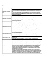
Icon
Option
External GPS. Configure serial GPS access.
License Manager. View license information for installed licensed applications.
Managed Programs. View install history for .NET programs.
Memory. Display current state of virtual memory.
Mixer. Adjust the input and output parameters – volume, side-tone, and record gain, for headphone, software and
microphone.
MX9WM Options. Set various device specific configuration options.
Peripherals. Enable or disable touch screen heater and scanner window heater, if installed. Set the heater trip
point in degrees C.
Regional Settings. Set appearance of numbers, currency, time and date based on country region and language
settings.
Registry. Load User Defaults, Save User Defaults, Load Factory Defaults, Warmboot and Restart.
Remove Programs. Remove user installed programs.
Screen. Calibrate touch screen, adjust text options.
Task Manager. Display running tasks. Cancel running tasks.
Wi-Fi. Set the parameters for a Summit client.
4-20
Icon
Option
WAN. Set up the wireless Wide Area Network. The WAN utilizes a cellular network instead of a spread spectrum
network.
Connections
Start > Settings > Connections
Icon
Option
Beam. Enable receiving InfraRed and Bluetooth beams. (Not supported on the MX9.)
Connections. Configure connections to servers.
Domain Enroll. Enroll in Active Directory domain.
Network Cards. Set the parameters for a wireless network using the utility included in Windows Mobile.
Wireless Manager. Provides information on the currently connected wireless network(s).
4-21
Settings Panels
About Info
Start > Settings > About Info
The data cannot be edited by the MX9 user on these panels.
Tab
Contents
Software
GUID, Windows CE Version, OAL Version, Bootloader Version, Compile Version, and
Language. Language indicates localized version.
Hardware
CPU Type, Codec Type, Keyboard, FPGA Type, Display, Flash memory, and DRAM
memory
Versions
Revision level of software modules and .NET Compact Framework Version. Utilities,
Drivers, Image, API, and Internet Explorer versions.
Network
Current IP address, MAC address, and gateway address for all network ports (radio,
ActiveSync).
Version window information is retrieved from the registry.
Version Tab and the Registry
Modify the Registry using the Registry Editor. Use caution when editing the Registry and make a backup copy of the registry
before changes are made.
The registry settings for the Version tab are under HKEY_LOCAL_MACHINE \ Software \ LXE \ Version in the registry.
To add a user application to the Version panel, create a new string value under the HKLM\Software\LXE\Version key. The
string name should be the Application name to appear in the Version window. The data for the value should be the version
number to appear in the Version window .
Version strings can be equal to or less than 254 characters. Because the strings are displayed in a text box, any number can be
accommodated, up to the 64K byte text box limitation.
Languages
The Software tab may display the current language. All languages are built into the OS image; English, French, German,
Simplified Chinese, Traditional Chinese, Japanese, Korean, Spanish, Thai.
Identifying Software Versions
The Versions tab displays the versions of many of the software programs installed. Not all installed software on the mobile
device is included in this list and the list varies depending on the applications loaded on the MX9. The Image line displays the
revision of the system software installed. Refer to the last three digits to determine the revision level.
MAC Address
The Network IP tab displays the MAC address of the network card.
4-22
Clock & Alarms
Start > Settings > Clock & Alarms
Time
Adjust the settings and tap ok to save the changes. Select Yes on the popup box and the changes take effect immediately. The
Time can be set for both a Home and a Visiting location.
4-23
Alarms
To set an alarm:
1. Tap the checkbox to enable the alarm.
2. Tap < Description > and enter a description. The description is limited to 63 characters.
3. Tap the day (or days) to play the alarm.
4. Tap the time to set the time to play the alarm. Set the time and tap ok to return to the Alarms panel.
5. Tap the Bell icon to set the notification. Notifications may include sound, light flash (the Alpha LED flashes) and
vibration. Set the desired options and tap ok to return to the Alarms panel.
6. Tap ok when finished to dismiss the Alarms panel.
4-24
More
Note:
Tap Start > Help for context sensitive Windows Mobile Help when changing or viewing options. Tap the X
icon in the top right corner to close Windows Mobile Help.
4-25
Lock
Start > Settings > Lock
Password
Set the lock / unlock behavior for the MX9.
Factory Default Settings
Prompt if device unused for
Unchecked
Timer
0 minutes
Password type
Simple PIN
Password
<blank>
Confirm
<blank>
Prompt if phone unused for – Check the checkbox and set the inactivity timeout before the MX9 locks. When selecting a
Password type the screen displays a numeric keypad or the input panel depending on the type of password selected.
Note:
Once a password has been entered, the password must be used to access the Lock panels again.
Select the Password type, Simple PIN (numeric) or strong alphanumeric. Enter the desired password and confirm. Note that
Windows Mobile places restrictions on what it considers a valid password. If the chosen password is not strong enough, a
warning is displayed and a new password should be entered and confirmed.
4-26
Hint
If the password entry isn’t successful after a predefined number of attempts, the password hint is displayed.
Factory Default Settings
Password hint
<blank>
4-27
Display
Unlock display defaults to Windows Classic. Windows Default can be selected to be the unlock display. Changing the unlock
display, and tapping OK (at the top right corner of the screen) presents the following screen:
Tap Yes to restart, or cold boot. Tap No to cancel the operation.
Note:
4-28
Tap Start > Help for context sensitive Windows Mobile Help when changing or viewing options. Tap the X
icon in the top right corner to close Windows Mobile Help.
Power
Start > Settings > System > Power
Reports the current battery state and allows the user to set suspend timeouts.
Battery
Battery power is displayed for both the main and internal Super-cap batteries.
4-29
Advanced
Factory Default Settings
On battery power:
Turn off device if not used for
Enabled
Timer setting
5 minutes
On external power:
Turn off device if not used for
Enabled
Timer setting
5 minutes
Select the inactivity timeout period before the MX9 goes into suspend. The settings on this panel are for the suspend timers
only. Backlight timers are set using the Backlight settings panel.
Note:
4-30
Tap Start > Help for context sensitive Windows Mobile Help when changing or viewing options. Tap the X
icon in the top right corner to close Windows Mobile Help.
Sounds & Notifications
Start > Settings > Personal > Sounds & Notifications
Set volume parameters and assign sound WAV files to Windows Mobile events. Options that cannot be edited by the user are
dimmed.
Factory Default Settings
Sounds
Events
Enabled
Programs
Enabled
Notifications
Enabled
Screen taps
Disabled
Hardware buttons
Disabled
Notifications
Play Sound
Disabled
Display message on screen
Disabled
Flash light for
Disabled
Vibrate
Disabled
Vibrations
Screen taps
Disabled
Short
Enabled
4-31
Sounds
Follow the instructions on the screen and tap ok to save the changes. Changes take effect immediately.
4-32
Notifications
The Event box lists several events that can have an associated notification. The notification, depending on the event selected,
may consist of playing a sound, displaying a screen message, flashing a light or triggering the vibration motor.
When finished, tap ok to save the changes.
4-33
Vibrations
Vibration on Screen taps is disabled by default. Check the checkbox to enable vibration on screen taps.
Short vibration is enabled by default.
When finished, tap ok to save the changes. Changes take effect immediately.
Note:
4-34
Tap Start > Help for context sensitive Windows Mobile Help when changing or viewing options. Tap the X
icon in the top right corner to close Windows Mobile Help.
Today
Start > Settings > Today
Configure the appearance and the items to display on the Today screen.
Use the Appearance panel to assign a theme for the device. The default theme is Windows Mobile Classic Blue. Any user
installed themes are included in the list.
Use the Items panel to select the items to be shown on the Start panel.
The Today timeout timer refers to the "return to Today screen" function. When the device is placed in Suspend, and the timer
expires, a return from Suspend displays the Today screen, not the application in focus when the MX9 was placed in Suspend.
The application in focus, which is running in the background, will need to be selected again.
4-35
Use Options to set display parameters for highlighted items in the Checked Items list.
Note:
4-36
Tap Start > Help for context sensitive Windows Mobile Help when changing or viewing options. Tap the X
icon in the top right corner to close Windows Mobile Help.
Personal Panels
Buttons
Start > Settings > Personal > Buttons
Program Buttons
Program buttons can be used to assign functions to certain keys such as F1 through F5 and the diamond keys. Buttons can
only be assigned to programs that have an icon in the Start menu or the Settings folder (including sub-folders). A program that
is not in the above mentioned locations does not show up in the list here. The 62-key keypad includes a Diamond 1 key. The
38-key keypad includes a Diamond 1 key and a Diamond 2 key.
Note:
The button links to the shortcut to the program, not the executable file.
Note:
The System Administrator uses the Buttons setting panels to assign a Status User key and a Status Admin key on
the Status Popup panel.
Factory Default Settings
38-Key Keypad
F1
Left Softkey
F2
Right Softkey
F3, F4, F5, D1, D2
<None>
62-Key Keypad
F1
Left Softkey
F2
Right Softkey
F3, F4, F5, D1
<None>
4-37
To assign a button:
1. Tap to highlight the desired button.
2. Select the program or shortcut from the Assign a program
pulldown box.
3. Tap ok.
4-38
Up/Down Control
Customize the delay before repeating and the repeat rate for the up/down controls.
Note:
Tap Start > Help for context sensitive Windows Mobile Help when changing or viewing options. Tap the X
icon in the top right corner to close Windows Mobile Help.
4-39
Input
Start > Settings > Personal > Input
Input Method
Select the preferred method of input.
Factory Default Settings
Input Method
Keyboard
Small keys
Enabled
The default method of input is the keyboard or input panel. When the cursor is located in a field allowing text input, the input
panel may automatically be displayed. If not automatically displayed, the input panel can be accessed by tapping on the
keyboard icon at the bottom center of the screen.
If a different input method is active, the icon for that input method is displayed instead of the keyboard icon.
Tap ok to save any changes.
4-40
Word Completion
Factory Default Settings
Suggest words when entering text
Enabled
Suggest after entering
A space
Suggest _ word(s)
4
Add a space after word
Enabled
Enable auto correct
Enabled
4-41
Options
Factory Default Settings
Voice recording format
8000 Hz, 8 Bit, Mono
Default zoom level for writing
200%
Default zoom level for typing
100%
Capitalize first letter of sentence
Enabled
Scroll upon reaching the last line
Enabled
Note:
4-42
Tap Start > Help for context sensitive Windows Mobile Help when changing or viewing options. Tap the X
icon in the top right corner to close Windows Mobile Help.
Owner Information
Start > Settings > Personal > Owner Information
Set the MX9 owner details.
Factory Default Settings
Identification
Name, Company, Address, Telephone, E-mail
Blank
Notes
Notes
Blank
Enter the information and tap ok to save the changes. The changes take effect immediately.
Note:
Owner Identification name listed in Start > Settings > Personal > Owner > Information is not used during Bluetooth
operation.
Note:
Tap Start > Help for context sensitive Windows Mobile Help when changing or viewing options. Tap the X
icon in the top right corner to close Windows Mobile Help.
4-43
System Panels
About
Start > Settings > System > About
The About panels show OS versions, allow device name and description input and display copyright information. The following
screens are examples only.
Version
This screen displays information on the installed operating system and the hardware.
Note that Windows Mobile is based on a Windows CE engine. The underlying version of Windows CE is displayed here.
4-44
Device ID
Factory Default Settings
Device Name
[device_specific]001
Device Description
WM_MX9
The device name and description can be changed. Enter the name and description using either the keypad or the Input Panel
and tap ok to save the changes. The changes take effect immediately.
Note:
Changing the device name deletes previous ActiveSync settings including backed up user files. Upon the next
ActiveSync session, a different Device name will be entered and the device will need to re-partner with ActiveSync.
Note:
The Device Name listed in Start > Settings > System > About > Device ID is not used during Bluetooth operation.
4-45
Copyrights
This screen is presented for information only. The Copyrights information cannot be changed by the user.
4-46
Administration - for AppLock
Introduction
AppLock is designed to be run on Windows based devices only. The AppLock program is installed before shipping.
MX9 AppLock is setup by the Administrator by tapping Start > Settings > System > Administration.
Configuration parameters are specified by the AppLock Administrator for the MX9 end-user. AppLock is password protected by
the Administrator.
End-user mode locks the end-user into the configured application or applications. The end user can still reboot the mobile
device and respond to dialog boxes. The administrator-specified applications are automatically launched in the specified order
and run in full screen mode when the MX9 boots up.
When the mobile device is reset to factory default values, for example after a cold reset, the Administrator may need to
reconfigure the AppLock parameters.
The assumption, in this section, is that the first user to power up a new mobile device is the system administrator.
Note:
AppLock Administrator panel file Launch option does not inter-relate with similarly-named options contained in other
MX9 System Panels.
Note:
A few applications do not follow normal procedures when closing. AppLock cannot prevent this type of application
from closing, but is notified that the application has closed. For these applications, AppLock immediately restarts the
application (see Auto Re-Launch) which causes the screen to flicker. If this type of application is being locked, the
administrator should close all other applications before switching to end-user mode to minimize the screen flicker.
AppLock is updated periodically as new options become available. Contact technical assistance for downloads and update
availability.
4-47
Factory Default Settings - AppLock
Application Panel
Filename
Blank
Title
Blank
Arguments
Blank
Order
1
Internet
Disabled
Global Key
Ctl+Spc / Ctrl+Spc
Global Delay
10 sec
Input Panel
Disabled
Launch Button Panel
Auto at Boot
Enabled
Auto at Boot Retries
0
Auto at Boot Delay
10 sec
Auto Re-launch
Enabled
Auto Re-launch Retries
0
Auto Re-launch Delay
0 sec
Manual Launch
Disabled
Allow Close
Disabled
Options Panel
Launch timeout
60000 msec
Replace timeout
20000 msec
Restart timeout
20000 msec
Security Panel
Hotkey (Activation key) 62 key
Shft+Ctl+A
Hotkey (Activation key) 38 key
Shift+Ctrl+Alpha+2
Password
Blank
Status Panel
Filename
\System\applock.txt
View Level
None
Log Level
None
4-48
Setup a New Device
Prerequisites:
l
The touch panel must be enabled. Refer to the (Start > Settings > Options > Misc) Touch Panel Disabled setting. If the
Touch Panel Disabled option is dimmed, the touch panel cannot be turned off by the user.
l
An MX9 default input method (Input Panel, Transcriber, or custom input method) is assigned.
Devices with AppLock are shipped to boot in Administration mode with no default password, thus when the device is first
booted, the user has full access to the MX9 and no password prompt is displayed. After the administrator specifies
applications to lock, a password is assigned and the device is rebooted or the hotkey is pressed, the MX9 switches to end-user
mode.
The process to configure a new device is as follows:
1. Insert a fully charged battery and press the Power button.
2. Connect an external power source to the device (if required).
3. Adjust screen display, audio volume and other parameters if desired. Install accessories (e.g., handstrap,
stylus).
4. Tap Start > Settings > System > Administration icon.
5. Assign a Switch Key (hotkey) sequence for AppLock. See Security Panel.
6. Assign an application on the Application tab screen. More than one application can be assigned.
7. Assign a password on the Security tab screen.
8. Select a view level on the Status Panel screen, if desired.
9. Tap OK.
10. Press the Switch Key sequence to launch AppLock and lock the configured application(s).
The device is now in end-user mode.
4-49
Administration Mode
Administration mode gives full access to the mobile device, hardware and software configuration options.
The administrator must enter a valid password (when a password has already been assigned) before access to Administration
mode and configuration options are allowed. The administrator can configure the following options:
l
Create/change the keystroke sequence to activate administrator access.
l
Create/change the password for administrator access.
l
Assign the name of the application, or applications, to lock.
l
Select the command line of the application to lock.
In addition to these configuration options, the administrator can view and manage the status logs of AppLock sessions.
Administrator default values for this device:
Administrator Hotkey
Shift+Ctrl+A
Password
none
Application path and name
none
Application command line
none
End User Mode
End-user mode locks the end-user into the configured application or applications. The end user can still reboot and respond to
dialog boxes. Each application is automatically launched and runs in full screen mode when the device boots up.
The user cannot unintentionally or intentionally exit the application nor can the end user execute any other applications. Normal
application exit or switching methods and all Microsoft defined Windows OS key combinations, such as close (X) icon, File
Exit, File Close, Alt-F4, Alt-Tab, etc. are disabled. The Windows OS desktop icons, menu bars, task bar and system trays are
not visible or accessible. Task Manager is not available.
If the end-user selects File/Exit or Close from the applications menu bar, the menu is cleared and nothing else happens; the
application remains active. Nothing happens when the end-user clicks on the Close icon on the application’s title bar and the
application remains active.
Note:
A few applications do not follow normal procedures when closing. AppLock cannot prevent this type of application
from closing, but is notified that the application has closed. For these applications, AppLock immediately restarts the
application which causes the screen to flicker. If this type of application is being locked, the administrator should close
all other applications before switching to end user mode to minimize the screen flicker.
Windows accelerator keys such as Alt-F4 are disabled.
4-50
Passwords
A password must be configured. If the password is not configured, a new device switches into Administration mode without
prompting for a password. In addition to the Administrator hotkey press, a mode switch occurs if inaccurate information has
been configured or if mandatory information is missing in the configuration.
There are several situations that display a password prompt after a password has been configured.
If the configured hotkey is pressed, the password prompt is displayed. In this case the user has 30 seconds (and within three
attempts) to enter a password. If a valid password is not entered within 30 seconds, the password prompt is dismissed and the
device returns to end-user mode.
All other situations that present the password prompt do not dismiss the prompt -- this is because the other situations result in
invalid end-user operation.
These conditions include:
l
If inaccurate configuration information is entered by the administrator, i.e., an application is specified that does not
exist.
l
If the application name, which is mandatory for end-user mode, is missing in the configuration.
l
Invalid installation of AppLock (e.g., missing DLLs).
l
Corrupted registry settings.
To summarize, if an error occurs that prevents AppLock from switching to user mode, the password will not timeout and
AppLock will wait until the correct password is entered.
AppLock Password Help
Contact technical assistance for help when troubleshooting passwords.
4-51
End-User Switching Technique
A checkmark in the switchpad menu (see image above) indicates applications currently active or available for Launching by the
user. When Keyboard is selected, the MX9 default input method (Input Panel, Transcriber, or custom input method) is
activated.
The check to the left of the application name indicates that the application is active.
If the application is listed but does not have a checkmark to the left of the application name, this means the application is
configured in AppLock and can be manually launched by tapping on the application name in the list.
Using a Stylus Tap
When the mobile device enters end-user mode, a Switchpad icon (it looks like three tiny windows one above the other) is
displayed in the lower right corner of the display. The Switchpad is always visible on top of the application in focus. However, if
only one application is configured in AppLock and the Input Panel is disabled the Switchpad is not visible.
When the user taps the Switchpad icon, a menu is displayed showing the applications available to the user. The user can tap
an application name in the popup menu and the selected application is brought to the foreground. The previous application
continues to run in the background. Stylus taps affect the application in focus only. When the user needs to use the Input
Panel, they tap the Keyboard option. Input Panel taps affect the application in focus only.
See Also: Application Panel > Launch > Manual (Launch) and Allow Close
Using the Switch Key Sequence
One switch key sequence (or hotkey) is defined by the administrator for the end-user to use when switching between locked
applications. This is known as the Activation key. The Activation key is assigned by the Administrator using the Global Key
parameter.
When the switch key sequence is pressed on the keypad, the next application in the AppLock configuration is moved to the
foreground and the previous application moves to the background. The previous application continues to run in the background.
End-user key presses affect the application in focus only.
See Also: Application Panel > Global Key
Hotkey (Activation hotkey)
If the mobile device uses AppLock to allow the user to switch between applications, the default Activation key is Ctrl+Spc.
The key sequence switches the focus between one application and another. Data entry affects the application running in the
foreground only. Note that the system administrator may have assigned a different key sequence to use when switching
applications.
4-52
Application Configuration
Settings > System > Administration icon
The default Administrator Hotkey sequence is Shift+Ctrl+A.
Administrator mode allows access to all features on the device. When the hotkey is pressed to switch into Administrator mode,
a password prompt is displayed (if a password has been configured). A password must be entered within 30 seconds (and
within three tries) or the password prompt is removed and the device remains in end-user mode with the focus returned to the
locked application. Without entry of a valid password, the switch into Administrator mode will not occur.
The password prompt is displayed if a password has been configured. When the valid password is entered, the Administration
panel is displayed. When a valid password is not entered within 30 seconds, the user is returned to the System Panel.
If a password has not been configured, the Administrator panel is displayed.
Important: Before setting up multiple instances of the same application, make sure the targeted software application
will allow two instances to run at the same time.
4-53
Application Panel
Use the Application tab options to select the applications to launch when the device boots up in End-user Mode.
If no application is specified when the Administrator Panel is closed, the MX9 reboots into Administrator mode. If a password
has been set, but an application has not been specified, the user will be prompted for the password before entering
administration mode. The password prompt remains on the display until a valid password is entered.
Option
Explanation
Filename
Default is blank. Move the cursor to the Filename text box and either type the application path or tap
the Browse button (the … button). The standard Windows Browse dialog is displayed. After selecting
the application from the Browse dialog, tap OK.
Title
Default is blank. Enter the Title to be associated with the application. The assumption is that multiple
copies of the same application may need unique titles in order to differentiate them in the Switchpad.
Arguments
Default is blank. Enter the command line parameters for the application in the Arguments text box.
Order
Default is 1. Enter the Order in which the application is to be loaded or presented to the end-user.
Applications are launched in lowest to highest number order and do not need to be sequential.
Internet
Default is Disabled. Enable the Internet checkbox to use the End-user Internet Explorer (EUIE.EXE)
When the checkbox is enabled, the Internet Menu and Internet Status are available. See the section
titled End-user Internet Explorer (EUIE) for more details.
Launch Button
See following section titled Launch Button.
Global Key
Default is Ctrl+Spc. Select the Global Key key sequence the end-user is to press when switching
between applications. The Global Key default key sequence must be defined by the AppLock Administrator. The Global key is presented to the end-user as the Activation key.
4-54
Option
Explanation
Global Delay
Default is 10 seconds. Enter the number of seconds that Applications must wait before starting to
run after reboot.
Note: Delay (Global) may not be available in all versions of AppLock. You can simulate a Global
Delay function by setting a delay for the first application (lowest Order) launched and setting
the delay to 0 for all other applications.
Input Panel
Default is Disabled. Enable (check) to show the Keyboard option on the Switchpad menu. When enabled the input panel cannot be enabled or disabled for each individual application, and is available to
the user for all configured applications.
Clear Button
Tap the Clear button to clear all currently displayed Filename or Application information. The Global
settings are not cleared.
Scroll Buttons
Use the left and right scroll buttons to move from application setup screen to application setup
screen. The left and right buttons update the information on the screen with the previous or next configured application respectively.
4-55
Launch Button
When clicked, displays the Launch options panel for the Filename selected on the Administration panel.
Note:
4-56
Launch order is determined by the Order specified in the Application tab. The Order value does not have to be
sequential.
Auto At Boot
Default is Enabled.
Auto At Boot
When enabled, automatically launches (subject to the specified Delay in seconds) the application after the unit is rebooted. If a
Delay in seconds is specified, AppLock waits for the specified period of time to expire before launching the application. The
Delay default value is 10 seconds; valid values are between 0 “no delay” and a maximum of 999 seconds.
Retries
This is the number of times the application launch will be retried if a failure occurs when the application is automatically
launched at bootup. Valid values are between 0 (no tries) and 99 tries or -1 for infinite. Infinite tries ends when the application
successfully launches. The default is 0 retries.
Delay
This timer is the time that AppLock waits prior to the initial launch of the selected application when it is automatically launched
at bootup. Delay default is 10 seconds. Valid values are between 0 seconds (no delay) and 999 seconds.
The Auto At Boot delay is associated for each application; it will be either a value specified by the Administrator or it will be the
delay default value. At startup, when a delay has been assigned for each application, AppLock waits for the delay associated
with the first application to expire before launching the first application then AppLock waits for the delay associated with the
second application to expire before launching the second application. AppLock continues in this manner until all applications
are launched.
Note:
A “Global Delay” can be accomplished by setting a timed delay for the first application to be launched (by lowest Order
number) and no delay (0 seconds) for all other applications.
Note:
Launch order is determined by the Order specified in the Application tab. The Order value does not have to be
sequential.
4-57
Auto Re-Launch
Default is Enabled.
When enabled for a specific application. automatically re-launches it (subject to the specified Auto Re-Launch Delay in
seconds) after it terminates. This option allows the Administrator to disable the re-launch operation. AppLock cannot prevent all
applications from closing. When an application that AppLock cannot prevent from closing terminates, perhaps because of an
error condition, AppLock re-launches the application when this option is enabled.
Note:
If Allow Close is enabled and both Auto Re-launch and Manual (Launch) are disabled, the application cannot be
restarted for the end-user or by the end-user after the application terminates.
Retries
Default is 0 tries. Retries is the number of times AppLock will try to re-launch the application. The retry count is reset after an
application is successfully launched and controlled by AppLock. Valid values are between 0 (no tries) and 99 tries or -1 for
infinite. Infinite tries ends when the application successfully launches.
Delay
Default is 0 seconds (no delay). Delay is the amount of time AppLock waits prior to re-launching an application that has
terminated. The delay is specified in seconds. Valid values are between 0 (no delay) and 99 seconds.
AppLock must also be configured to automatically re-launch an application. To AppLock, application termination by the enduser is indistinguishable from application termination for any other reason.
4-58
Manual (Launch)
Default is Disabled. Enabling this option allows the end-user to launch the specified application(s). Upon bootup completion an
application with Manual enabled is listed on the Switchpad accompanied by a checkmark that indicates the application is
currently active or available for Launching. When an application name is tapped by the end-user, the application is launched (if
inactive) and brought to the foreground.
Applications set up with Manual (Launch) enabled may or may not be launched at bootup. This function is based on the
application’s Auto At Boot setting. The applications have been listed as approved applications for end-user manual launch
using the Switchpad menu structure. The approved applications are listed on the Switchpad. A checkmark indicates the
applications active status.
When Manual (Launch) is disabled for an application, and Allow Close is enabled for the application, when the end-user closes
the specific application it is no longer available (shown) on the Switchpad.
When Auto At Boot and Manual (Launch) are both disabled for a specific application, the application is 1) not placed on the list
of approved applications for end-user manual launch and 2) never launched, and 3) not displayed on the Switchpad.
Match
Default is blank (Match is not used).
AppLock works by associating display windows with the launched process ID. If an application uses different process IDs for
windows it creates, the Match field must be used.
Use the Match field to specify up to 32 characters of the class name for the application.
l
DOS applications using a standard DOS display box should specify condev_appcls in the Match textbox.
l
Remote Desktop (remote.exe) should specify TSSHELLWND in the Match textbox.
Note:
An update may be required to support locking remote.exe. Contact technical assistance for details.
Allow close
Default is Disabled. When enabled, the associated application can be closed by the end-user.
This option allows the administrator to configure applications that consume system resources to be terminated if an error
condition occurs or at the end-user’s request. Error conditions may generate a topmost popup requiring an end-user response,
memory resource issues requiring an end-user response, etc. Also at the administrator’s discretion, these types of applications
can be started manually (see Manual [Launch]) by the end-user.
4-59
End User Internet Explorer (EUIE)
AppLock supports applications that utilize Internet Explorer, such as .HTML pages and JAVA applications. The end user can
run an application by entering the application name and path in Internet Explorer’s address bar.
To prevent the end user from executing an application using this method, the address bar and Options settings dialog are
restricted in Internet Explorer. This is accomplished by creating an Internet Explorer that is used in end user mode: End-user
Internet Explorer (EUIE.EXE). The EUIE executes the Internet Explorer application in full screen mode which removes the
address bar and status bar. The Options Dialog is also removed so the end user cannot re-enable the address bar.
The administrator specifies the EUIE by checking the Internet checkbox in the Application tab of the Administrator applet. The
internet application should then be entered in the Application text box.
When the Internet checkbox is enabled, the Menu and Status check boxes are available.
Enabling the Menu checkbox displays the EUIE menu which contains navigation functions like Back, Forward, Home,
Refresh, etc., functions that are familiar to most Internet Explorer users. When the Menu checkbox is blank, the EUIE menu is
not displayed and Navigation functions are unavailable.
When the Status checkbox is enabled, the status bar displayed by EUIE gives feedback to the end-user when they are
navigating the Internet.
If the standard Internet Explorer that is shipped with the mobile device is desired, it should be treated like any other application.
This means that IEXPLORER.EXE (or equivalent) should be specified in the Application text box and the internet application
should be entered in the command line. In this case, do not check the Internet checkbox.
4-60
Security Panel
Setting an Activation Hotkey
Specify the hotkey sequence that triggers AppLock to switch between administrator and user modes and the password
required to enter Administrator mode. The default hotkey sequence is Shift+Ctrl+A.
A 2nd key keypress is an invalid keypress for a hotkey sequence.
Move the cursor to the Hot Key text box. Enter the new hot key sequence by first pressing the Shift state key followed by a
normal key. The hotkey selected must be a key sequence that the application being locked does not use. The hotkey sequence
is intercepted by AppLock and is not passed to the application.
Input from the keyboard or Input Panel is accepted with the restriction that the normal key must be pressed from the keyboard
when switching modes. The hotkey sequence is displayed in the Hot key text box with <Shift>, <Alt>, and <Ctrl> text strings
representing the shift state keys. The normal keyboard key completes the hotkey sequence. The hotkey must be entered via
the keypad. Some hotkeys cannot be entered via the Input Panel. Also, hotkeys entered via the SIP1 are not guaranteed to
work properly when switching operational modes.
For example, if the <Ctrl> key is pressed followed by <A>, Ctrl+A is entered in the text box. If another key is pressed after a
normal key press, the hotkey sequence is cleared and a new hotkey sequence is started.
A normal key is required for the hotkey sequence and is unlike pressing the normal key during a mode switch; this key can be
entered from the SIP when configuring the key. However, when the hotkey is pressed to switch user modes, the normal key
must be entered from the keypad; it cannot be entered from the SIP.
1Soft Input Panel. The keyboard that appears on the display when the cursor is placed in a text input box.
4-61
Setting a Password in the Security Panel
Move the cursor to the Password text box. The passwords entered in the Password and Confirm Password fields must match.
Passwords are case sensitive.
When the user exits the Administrator panel, the two passwords are compared to verify that they match. If they do not match, a
dialog box is displayed notifying the user of the error. After the user closes the dialog box, the Security Panel is displayed and
the password can then be entered and confirmed again. If the passwords match, the password is encrypted and saved.
See Also: "Passwords"
4-62
Options Panel
AppLock uses 3 timeout values when locking applications:
Launch timeout -- the time to wait for an application to initially launch before timing out. Default value is 60000 milliseconds (60
seconds).
Replace timeout -- the time to wait for an application to replace the current window with another one before timing out. Default
value is 20000 milliseconds (20 seconds).
Restart timeout -- the time to wait for an application to restart itself before timing out. Default value is 20000 milliseconds (20
seconds).
4-63
Status Panel
Use the Status panel to view the log of previous AppLock operations and to configure which messages are to be recorded
during AppLock operation.
Status information is stored in a specific location on the storage device and in a specific logfile specified by the Administrator.
For this reason, the administrator can configure the type of status information that is logged, as well as clear the status
information.
Move the cursor to the Filename text box and either type the logfile path or tap the Browse button (the … button). The standard
Windows OS Browse dialog is displayed. After selecting the logfile from the Browse dialog, tap OK.
View
Error
Error status messages are logged when an error occurs and is intended to be used by the administrator to determine why the specified application cannot be locked.
Process
Processing status shows the flow control of AppLock components and is mainly intended for Customer Support
when helping users troubleshoot problems with their AppLock program.
Extended Extended status provides more detailed information than that logged by Process Logging.
All
All messages are displayed.
Tap the Refresh button after changing from one view level to another. The filtered records are displayed, all others are not
displayed.
4-64
Log
Note:
If a level higher than Error is selected, the status should be cleared frequently by the administrator.
In addition to the three view levels the administrator can select that all status information be logged or turn off all status
information logging completely. The system default is ‘None’; however to reduce registry use, the administrator may want to
select ‘None’ after verifying the configuration. Tap the Clear button to clear the status information from the registry.
l
None
l
Error
l
Processing
l
Extended
l
All
Save As
When the 'Save As'… button is selected, a standard 'Save As' dialog screen is displayed. Specify the path and filename. If the
filename exists, the user is prompted whether the file should be overwritten. If the file does not exist, it is created.
See Also: "AppLock Error Messages"
4-65
AppLock Help
The mobile device won’t switch from Administration mode to end-user mode.
l
If the configuration is valid for one application but not the other, the switch to end-user mode fails. AppLock stays in
Administration mode and is stopped until the Administrator password is entered.
l
If two copies of the same application are configured, but the application only allows one copy to run at a time, for
example Microsoft Pocket Word and RFTerm, the switch to end-user fails. AppLock stays in Administration mode and
is stopped until the Administrator password is entered.
The hotkey sequence needed is not allowed. What does this mean?
When the Administrator is selecting a hotkey sequence to use when switching user modes, they are not allowed to enter key
combinations that are reserved by installed software applications. Honeywell has validated RFTerm key combinations ONLY.
When RFTerm is installed on the mobile device and an RFTerm restricted key sequence is specified as a hotkey sequence by
the Administrator, the following error message is displayed in a message box:
Selected hotkey is not allowed. Please reenter.
When RFTerm is not installed on the mobile device, the RFTerm keys are not restricted from use.
Can’t locate the password that has been set by the administrator?
Contact technical assistance for help.
See Also: "AppLock Error Messages"
4-66
AppLock Error Messages
Any messages whose first word is an ‘ing’ word is output prior to the action described in the message. For example, “Switching
to admin-hotkey press” is logged after the administrator has pressed the hotkey but prior to starting the switch process.
For all operations that can result in an error, an Error level message is displayed when a failure occurs. These messages
contain the word “failure”. These messages have a partner Extended level message that is logged which contains the word
“OK” if the action completed successfully rather than with an error.
For processing level messages, “Enter…” is logged at the beginning of the function specified in the message and “Exit…” is
logged at the end (just before the return) of the function specified in the message.
Message
Explanation and/or corrective action
Level
Error reading hotkey
The hotkey is read but not required by AppLock.
LOG_EX
Error reading hotkey;
using default
A hotkey is required. If there is a failure reading the hotkey, the internal factory default is used.
LOG_ERROR
App Command Line=
<Command line>
Command line of the application being locked
LOG_PROCESSING
App= <Application name>
Name of the application being locked
LOG_PROCESSING
dwProcessID= <#>
Device ID of the application being locked
LOG_EX
Encrypt exported key len
<#>
Size of encrypt export key
LOG_EX
Encrypt password length=
<#>
The length of the encrypted password.
LOG_EX
Encrypted data len <#>
Length of the encrypted password
LOG_EX
hProcess= <#>
Handle of the application being locked
LOG_EX
Key pressed = <#>
A key has been pressed and trapped by the hotkey processing.
LOG_EX
*****************
The status information is being saved to a file and the file has been opened successfully.
LOG_EX
AppLock found the kbdhook.dll, but was unable to get the address of the initialization procedure. For some reaAddress of keyboard hook son the dll is corrupted. Look in the \Windows directory for kbdhook.dll. If it exists, delete it. Also delete
LOG_ERROR
procedure failure
AppLock.exe from the \Windows directory and reboot the unit. Deleting AppLock.exe triggers the AppLock system to reload.
Address of keyboard hook
AppLock successfully retrieved the address of the keyboard filter initialization procedure.
procedure OK
LOG_EX
Alt pressed
The Alt key has been pressed and trapped by the HotKey processing.
LOG_EX
Alt
Processing the hotkey and backdoor entry
LOG_EX
Application handle search
failure
The application being locked did not complete initialization.
LOG_ERROR
Application handle search
OK
The application initialized itself successfully
LOG_ERROR
Application load failure
The application could not be launched by AppLock; the application could not be found or is corrupted.
LOG_ERROR
Backdoor message
received
The backdoor keys have been pressed. The backdoor hotkeys provide a method for customer service to get a
user back into their system without editing the registry or reloading the device.
LOG_PROCESSING
Cannot find kbdhook.dll
The load of the keyboard filter failed. This occurs when the dll is missing or is corrupted. Look in the \Windows
directory for kbdhook.dll. If it exists, delete it. Also delete AppLock.exe from the \Windows directory and reboot
the unit. Deleting AppLock.exe triggers the AppLock system to reload.
LOG_ERROR
Converted Pwd
Converted password from wide to mbs.
LOG_EX
4-67
Message
Explanation and/or corrective action
Level
Could not create event
EVT_HOTKEYCHG
The keyboard filter uses this event at the Administrator Control panel. The event could not be created.
LOG_ERROR
Could not hook keyboard
If the keyboard cannot be controlled, AppLock cannot process the hotkey. This failure prevents a mode switch
into user mode.
LOG_ERROR
Could not start thread HotThe keyboard filter must watch for hot key changes. The watch process could not be initiated.
KeyMon
LOG_ERROR
Ctrl after L or X
Processing the backdoor entry.
LOG_EX
Ctrl pressed
The Ctrl key has been pressed and trapped by the HotKey processing.
LOG_EX
Ctrl
Processing the hotkey and backdoor entry.
LOG_EX
Decrypt acquire context
failure
Unable to decrypt password.
LOG_ERROR
Decrypt acquired context
OK
Decryption process ok.
LOG_EX
Decrypt create hash failure
Unable to decrypt password.
LOG_ERROR
Decrypt created hash OK
Decryption process ok.
LOG_EX
Decrypt failure
Unable to decrypt password.
LOG_ERROR
Decrypt import key failure
Unable to decrypt password.
LOG_ERROR
Decrypt imported key OK
Decryption process ok.
LOG_EX
Encrypt acquire context
failure
Unable to encrypt password.
LOG_ERROR
Encrypt acquire encrypt
context failure
Unable to encrypt password.
LOG_ERROR
Encrypt acquired encrypt
context OK
Encrypt password process successful.
LOG_EX
Encrypt create hash failure
Unable to encrypt password.
LOG_ERROR
Encrypt create key failure
Unable to encrypt password.
LOG_ERROR
Encrypt created encrypt
hash OK
Encrypt password process successful.
LOG_EX
Encrypt export key failure
Unable to encrypt password.
LOG_ERROR
Encrypt export key length
failure
Unable to encrypt password.
LOG_ERROR
Encrypt exported key OK
Encrypt password process successful.
LOG_EX
Encrypt failure
The password encryption failed.
LOG_ERROR
Encrypt gen key failure
Unable to encrypt password.
LOG_ERROR
Encrypt generate key failure
Unable to encrypt password.
LOG_ERROR
Encrypt get user key failure
Unable to encrypt password.
LOG_ERROR
Encrypt get user key ok
Encrypt password process successful.
LOG_EX
Encrypt hash data failure
Unable to encrypt password.
LOG_ERROR
Encrypt hash data from
pwd OK
Encrypt password process successful.
LOG_EX
4-68
Message
Explanation and/or corrective action
Level
Encrypt length failure
Unable to encrypt password.
LOG_ERROR
Encrypt out of memory for
key
Unable to encrypt password.
LOG_ERROR
Encrypted data OK
The password has been successfully encrypted.
LOG_EX
Enter AppLockEnumWindows
In order for AppLock to control the application being locked so it can prevent the application from exiting,
AppLock launches the application and has to wait until it has created and initialized its main window. This message is logged when the function that waits for the application initialization is entered.
LOG_EX
Enter DecryptPwd
Entering the password decryption process.
LOG_PROCESSING
Enter EncryptPwd
Entering the password encryption processing.
LOG_PROCESSING
Enter FullScreenMode
Entering the function that switches the screen mode. In full screen mode, the taskbar is hidden and disabled.
LOG_PROCESSING
Enter GetAppInfo
Processing is at the beginning of the function that retrieves the application information from the registry.
LOG_PROCESSING
Enter password dialog
Entering the password dialog processing.
LOG_PROCESSING
Enter password timeout
Entering the password timeout processing.
LOG_PROCESSING
Enter restart app timer
Some application shut down before AppLock can stop it. In these cases, AppLock gets notification of the exit.
When the notification is received, AppLock starts a timer to restart the application. This message logs that the
timer has expired and the processing is at the beginning of the timer function.
LOG_PROCESSING
Enter TaskbarScreenMode
Entering the function that switches the screen to non-full screen mode and enable the taskbar.
LOG_PROCESSING
Enter ToAdmin
Entering the function that handles a mode switch into admin mode.
LOG_PROCESSING
Enter ToUser
Entering the function that handles the mode switch to user mode
LOG_PROCESSING
Enter verify password
Entering the password verification processing.
LOG_PROCESSING
Exit AppLockEnumWindows-Found
There are two exit paths from the enumeration function. This message denotes the enumeration function
found the application.
LOG_PROCESSING
Exit AppLockEnumWindows-Not found
There are two exit paths from the enumeration function. This message denotes the enumeration function did
not find the application.
LOG_PROCESSING
Exit DecryptPwd
Exiting password decryption processing.
LOG_PROCESSING
Exit EncryptPwd
Exiting password encryption processing.
LOG_PROCESSING
Exit FullScreenMode
Exiting the function that switches the screen to full screen.
LOG_PROCESSING
Exit GetAppInfo
Processing is at the end of the function that retrieved the application information from the registry.
LOG_PROCESSING
Exit password dialog
Exiting password prompt processing.
LOG_PROCESSING
Exit password dialog-cancel
Exiting password prompt w/cancel.
LOG_PROCESSING
Exit password dialog-OK
Exiting password prompt successfully.
LOG_PROCESSING
4-69
Message
Explanation and/or corrective action
Level
Exit password timeout
Exiting password timeout processing.
LOG_PROCESSING
Exit restart app timer
Processing is at the end of the timer function
LOG_PROCESSING
Exit TaskbarScreenMode
Exiting the function that switches the screen mode back to normal operation for the administrator.
LOG_PROCESSING
Exit ToAdmin
Exiting the function that handles the mode switch into admin mode.
LOG_PROCESSING
Exit ToUser
Exiting the user mode switch function.
LOG_PROCESSING
Exit ToUser-Registry read
The AppName value does not exist in the registry so user mode cannot be entered.
failure
LOG_PROCESSING
Exit verify password-no
pwd set
Exiting password verification.
LOG_PROCESSING
Exit verify passwordresponse from dialog
Exiting password verification.
LOG_PROCESSING
Found taskbar
The handle to the taskbar has been found so that AppLock can disable it in user mode.
LOG_PROCESSING
Getting address of keyboard hook init procedure
AppLock is retrieving the address of the keyboard hook.
LOG_PROCESSING
Getting configuration from
registry
The AppLock configuration is being read from the registry. This occurs at initialization and also at entry into
user mode. The registry must be re-read at entry into user mode in case the administration changed the settings of the application being controlled.
LOG_PROCESSING
Getting encrypt pwd
length
The length of the encrypted password is being calculated.
LOG_EX
Hook wndproc failure
AppLock is unable to lock the application. This could happen if the application being locked encountered an
error after performing its initialization and shut itself down prior to being locked by AppLock.
LOG_ERROR
Hook wndproc of open
app failure
The application is open, but AppLock cannot lock it.
LOG_ERROR
Hot key event creation failThe Admin applet is unable to create the hotkey notification.
ure
LOG_ERROR
Hot key pressed
Processing the hotkey and backdoor entry
LOG_EX
Hot key pressed
Processing the hotkey and backdoor entry
LOG_EX
Hot key set event failure
When the administrator changes the hotkey configuration the hotkey controller must be notified. This notification failed.
LOG_ERROR
Hotkey press message
received
The user just pressed the configured hotkey.
LOG_PROCESSING
In app hook:WM_SIZE
In addition to preventing the locked application from exiting, AppLock must also prevent the application from
enabling the taskbar and resizing the application’s window. This message traps a change in the window size
and corrects it.
LOG_EX
In app hook:WM_WINDOWPOSCHANGED
In addition to preventing the locked application from exiting, AppLock must also prevent the application from
enabling the taskbar and resizing the application’s window. This message traps a change in the window position and corrects it.
LOG_EX
Initializing keyboard hook
procedure
AppLock is calling the keyboard hook initialization.
LOG_PROCESSING
Keyboard hook initialization failure
The keyboard filter initialization failed.
LOG_ERROR
4-70
Message
Keyboard hook loaded OK
Explanation and/or corrective action
Level
The keyboard hook dll exists and loaded successfully.
LOG_EX
L after Ctrl
Processing the backdoor entry.
LOG_EX
Loading keyboard hook
When AppLock first loads, it loads a dll that contains the keyboard hook processing. This message is logged
prior to the load attempt.
LOG_PROCESSING
Open failure
The status information is being saved to a file and the file open has failed. This could occur if the file is write protected. If the file does not exist, it is created.
LOG_ERROR
Open registry failure
If the Administration registry key does not exist, the switch to user mode fails because the AppName value in
the Administration key is not available.
LOG_ERROR
Opened status file
The status information is being saved to a file and the file has been opened successfully.
LOG_EX
Out of memory for
encrypted pwd
Not enough memory to encrypt the password.
LOG_ERROR
pRealTaskbarWndProc
already set
The taskbar control has already been installed.
LOG_EX
Pwd cancelled or invalidremain in user mode
The password prompt was cancelled by the user or the maximum number of failed attempts to enter a password was exceeded.
LOG_EX
Read registry error-hot
key
The hotkey registry entry is missing or empty. This is not considered an error. The keyboard hook uses an
embedded default if the value is not set in the registry.
LOG_ERROR
Read registry failure-app
name
AppName registry value does not exist or is empty. This constitutes a failure for switching into user mode.
LOG_ERROR
Read registry failure-Cmd
Line
AppCommandLine registry entry is missing or empty. This is not considered an error since command line inforLOG_ERROR
mation is not necessary to launch and lock the application.
Read registry failure-Inter- The Internet registry entry is missing or empty. This is not considered an error since the Internet value is not
net
necessary to launch and lock the application.
LOG_ERROR
Registering Backdoor
MSG
The AppLock system communicates with the keyboard hook via a user defined message. Both AppLock.exe
and Kbdhook.dll register the message at initialization.
LOG_PROCESSING
Registering Hotkey MSG
The AppLock system communicates with the keyboard hook via a user defined message. Both Applock.exe
and Kbdhook.dll register the message at initialization.
LOG_PROCESSING
Registry read failure at
reenter user mode
The registry has to be read when entering user mode is the AppName is missing. This user mode entry is
attempted at boot and after a hotkey switch when the administrator has closed the application being locked or
has changed the application name or command line.
LOG_ERROR
Registry read failure at
reenter user mode
The registry has to be read when switching into user mode. This is because the administrator can change the
settings during administration mode. The read of the registry failed which means the Administration key was
not found or the AppName value was missing or empty.
LOG_ERROR
Registry read failure
The registry read failed. The registry information read when this message is logged is the application information. It the Administration key cannot be opened or if the AppName value is missing or empty, this error is
logged. The other application information is not required. If the AppName value is not available, AppLock cannot switch into user mode.
LOG_ERROR
Reset system work area
failure
The system work area is adjusted when in user mode to cover the taskbar area. The system work area has to
be adjusted to exclude the taskbar area in administration mode. AppLock was unable to adjust this area.
LOG_ERROR
Shift pressed
The Shift key has been pressed and trapped by the HotKey processing.
LOG_EX
Shift
Processing the hotkey and backdoor entry
LOG_EX
Show taskbar
The taskbar is now being made visible and enabled.
LOG_PROCESSING
Switching to admin-backdoor
The system is currently in user mode and is now switching to admin mode. The switch occurred because of the
backdoor key presses were entered by the administrator.
LOG_PROCESSING
Switching to admin-hotkey The system is currently in user mode and is now switching to admin mode. The switch occurred because of a
press
hotkey press by the administrator.
LOG_PROCESSING
4-71
Message
Switching to adminkbdhook.dll not found
Explanation and/or corrective action
Level
The keyboard hook load failed, so AppLock switches to admin mode. If a password is specified, the password
prompt is displayed and remains until a valid password is entered.
LOG_PROCESSING
Switching to admin-keyIf the keyboard hook initialization fails, AppLock switches to admin mode. If a password is specified, the passboard hook initialization failword prompt is displayed and remains until a valid password is entered.
ure
LOG_PROCESSING
Switching to admin-registry read failure
See the explanation of the “Registry read failure” above. AppLock is switching into Admin mode. If a password
has been configured, the prompt will be displayed and will not be dismissed until a valid password is entered.
LOG_PROCESSING
Switching to TaskbarScreenMode
In administration mode, the taskbar is visible and enabled.
LOG_EX
Switching to user mode
The registry was successfully read and AppLock is starting the process to switch to user mode.
LOG_PROCESSING
Switching to user-hotkey
press
The system is currently in admin mode and is now switching to user mode. The switch occurred because of a
hotkey press by the administrator.
LOG_PROCESSING
Taskbar hook failure
AppLock is unable to control the taskbar to prevent the locked application from re-enabling it.
LOG_ERROR
Taskbar hook OK
AppLock successfully installed control of the taskbar.
LOG_EX
Timeout looking for app
window
After the application is launched, AppLock must wait until the application has initialized itself before proceeding.
The application did not start successfully and AppLock has timed out.
LOG_ERROR
ToUser after admin, not at The user mode switch is attempted when the device boots and after the administrator presses the hotkey. The
boot
mode switch is being attempted after a hotkey press.
LOG_EX
ToUser after admin-app
still open
The switch to user mode is being made via a hotkey press and the administrator has left the application open
and has not made any changes in the configuration.
LOG_EX
ToUser after admin-no
app or cmd line change
If user mode is being entered via a hotkey press, the administrator may have left the configured application
open. If so, AppLock does not launch the application again unless a new application or command line has been
specified; otherwise, it just locks it.
LOG_EX
Unable to move desktop
The desktop is moved when switching into user mode. This prevents them from being visible if the application is
LOG_ERROR
exited and restarted by the timer. This error does not affect the screen mode switch; processing continues.
Unable to move taskbar
The taskbar is moved when switching into user mode. This prevents them from being visible if the application is
exited and restarted by the timer. This error does not affect the screen mode switch; processing continues.
LOG_ERROR
Unhook taskbar wndproc
failure
AppLock could not remove its control of the taskbar. This error does not affect AppLock processing
LOG_ERROR
Unhook wndproc failure
AppLock could not remove the hook that allows monitoring of the application.
LOG_ERROR
Unhooking taskbar
In administration mode, the taskbar should return to normal operation, so AppLock’s control of the taskbar
should be removed.
LOG_EX
Unhooking wndproc
When the administrator leaves user mode, the device is fully operational; therefore, AppLock must stop monitoring the locked application.
LOG_EX
WM_SIZE adjusted
This message denotes that AppLock has readjusted the window size.
LOG_EX
X after Ctrl+L
Processing the backdoor entry.
LOG_EX
Ret from password <#>
Return value from password dialog.
LOG_EX
Decrypt data len <#>
Length of decrypted password.
LOG_EX
Window handle to enumwindows=%x
The window handle that is passed to the enumeration function. This message can be used by engineering with
other development tools to trouble shoot application lock failures.
LOG_EX
WM_WINDOWPOSCHG
adjusted=%x
Output the window size after it has been adjusted by AppLock
LOG_EX
4-72
Backlight
Start > Settings > System > Backlight
Set the power management timers for the display and keyboard backlights. Set the display brightness for battery and external
power.
IMPORTANT – When the backlight timer expires, the display backlight and the display are OFF, as is the keypad backlight.
This is the System Idle state, there are no other Idle states.
Battery Power
Factory Default Settings
Turn off backlight if device not used for
Enabled
Timer
30 seconds
Turn on backlight when a button is pressed or the screen is
tapped
Enabled
Note:
Turn on backlight when a button is pressed or the screen is tapped: This affects wake-up from Suspend only.
With this unchecked, the device does not wake-up from Suspend on touch or key press. It will wake-up on other
events or Power key press.
When the MX9 is on battery power and the backlight timer expires, the display and the backlights for the display and keypad
are turned off. Default value is 30 seconds and both the check boxes are enabled. Adjust the settings and tap OK to save the
changes. The changes take effect immediately.
4-73
External Power
Factory Default Settings
Turn off backlight if device is not
used for
Enabled
Timer
1 min
Turn on backlight when a button is
pressed or the screen is tapped
Enabled
This option is always Enabled,
unchecking this option has no effect.
When the MX9 is on external power and the backlight timer expires, the display and the backlights for the display and keypad
are turned off. Default value is 1 minute and both the check boxes are enabled. Adjust the settings and tap ok to save the
changes. The changes take effect immediately.
Note:
4-74
Tap Start > Help for context sensitive Windows Mobile Help when changing or viewing options. Tap the X
icon in the top right corner to close Windows Mobile Help.
Bluetooth
Start > Settings > System > Bluetooth
Note:
Contact technical assistance for upgrade availability if your Bluetooth panels are not the same as the panels
presented in this section.
Discover and manage pairing with nearby Bluetooth devices.
Factory Default Settings
Discovered Devices
None
Settings
Turn On Bluetooth
Disabled / default is Off
Computer is connectable
Enabled
Computer is discoverable
Disabled
Prompt if devices request to pair
Enabled
Continuous search
Disabled
Filtered Mode
Enabled
Printer Port on COM9:
Disabled (unchecked) by default in both Filtered
and Non Filtered Modes. The option is dimmed
in Non Filtered Mode.
Logging
Disabled
Computer Friendly Name
[System Name]
Reconnect
Report lost connection
Enabled
Report when reconnected
Disabled
Report failure to reconnect
Enabled
Clear Pairing Table on boot
Disabled
Auto Reconnect on Boot
Enabled
Auto Reconnect
Enabled
4-75
Bluetooth icon (at the bottom of the Today panel) state and Bluetooth device icon states change as Bluetooth devices are
discovered, paired, connected and disconnected. There may be audible or visual signals as paired devices re-connect with the
MX9.
l
The default Bluetooth setting is Off.
l
The MX9 cannot be discovered by other Bluetooth devices when the Computer is discoverable option is disabled
(unchecked) on the Settings panel.
l
Other Bluetooth devices cannot be discovered if they have been set up to be Non-Discoverable or Invisible.
l
When Filtered Mode is enabled, the MX9 can pair with one Bluetooth scanner and one Bluetooth printer.
l
When Filtered Mode is disabled, the MX9 can pair with up to four Bluetooth devices, with a limit of one scanner, one
printer, two HID1 devices (one Mouse, one Keyboard), one PAN2 device, and one DUN3 device connected at the same
time.
l
It is not necessary to disconnect a paired scanner and printer before a different scanner or printer is paired with the MX9.
l
The target Bluetooth device should be as close as possible (up to 32.8 ft (10 meters) Line of Sight) to the MX9 during the
pairing process.
Assumption:The System Administrator has Discovered and Paired targeted Bluetooth devices for the MX9. The MX9 operating
system has been upgraded to the revision level required for Bluetooth client operation. An application (or API) is available that
will accept data from serial Bluetooth devices.
1Human Interface Device profiles used by Bluetooth keyboards, mice, pointing devices and remote monitoring devices.
2Personal Area Networking profile. Un-modified Ethernet payloads (using BNEP) can exchange packets between Bluetooth
devices. PANU is a PAN User service that uses either the NAP or the GN service.
3Dial-Up Networking provides access to the Internet and other dial-up services using Bluetooth technology.
4-76
Initial Configuration
1. Select Start > Settings > System > Bluetooth or tap the Bluetooth icon at the bottom of the Today panel.
2. Tap the Settings Tab.
3. Change the Computer Friendly Name at the bottom of the Settings panel. The Bluetooth MX9 default name is
determined by the factory installed software version. Honeywell strongly urges assigning every MX9 a unique name (up
to 32 characters) before Bluetooth Discovery is initiated.
4. Check or uncheck the MX9 Bluetooth options on the Settings tab and the Reconnect tab.
5. Tap the OK button to save your changes.
Subsequent Use
Note:
Today panel icon and Bluetooth device Icon states change as Bluetooth devices are discovered, paired, connected
and disconnected. A Today panel Bluetooth icon with a red background indicates Bluetooth is active and not paired
with any device. A device icon with a red background indicates a disconnected paired device.
1. Tap the Bluetooth icon at the bottom of the Today panel to open the Bluetooth LXEZ Pairing application.
2. Tap the Bluetooth Devices tab.
3. Tap the Discover button. When the Bluetooth module begins searching for in-range Bluetooth devices, the button name
changes to Stop. Tap the Stop button to cancel the Discover function at any time.
4. The discovered devices are listed in the Bluetooth Devices window.
5. Highlight a Bluetooth device in the Discovered window and double-tap to open the device properties menu.
6. Tap Pair as Scanner to set up the MX9 to receive scanner data.
7. Tap Pair as Printer to set up the MX9 to send data to the printer.
8. Tap Serial Device (when Filtered mode is disabled) to set up the MX9 to communicate with a Bluetooth serial device.
9. Tap HID Device to pair a HID device.
10. Tap PAN Device to pair a PAN device.
11. Tap DUN Device to pair a DUN device.
12. Tap Disconnect to stop pairing with the device. Once disconnected, tap Clear to remove the device name and data
from the MX9 Bluetooth Devices list. Select Yes at the "Delete all disconnected devices? Yes / No" dialog box.
Upon successful pairing, the selected device may react to indicate a successful connection. The reaction may be an audio
signal from the device, flashing LED on the device, or a dialog box is placed on the MX9 display.
Whenever the MX9 is turned On, all previously paired, live, Bluetooth devices in the vicinity are paired, one at a time, with the
MX9. If the devices cannot connect to the MX9 before the re-connect timeout time period expires (default is approximately 20
seconds for each paired device) there is no indication of the continuing disconnect state if Report Failure to Reconnect is
disabled.
4-77
Bluetooth Devices
The Bluetooth Devices tab displays any device previously discovered and paired with the MX9.
Before Discover (or initial setup)
After Discover
Clear Button
Deletes all devices from the Device table that are not currently paired. A dialog box is presented.
Tap the Yes button to remove disconnected or deleted devices from the device table. The devices are removed from the
Device table after any reboot sequence and when LXEZ Pairing is re-launched without rebooting. Tap the No button to make no
changes.
See Also: "Clear Pairing Table on Boot"
4-78
Discover Button
When tapped, the Bluetooth client discovers and displays all Bluetooth devices in the vicinity. Bluetooth managed devices
should be as close as possible1, in direct line of sight, with the MX9 during the Discover process.
At the end of the Discover process, and when Filtered Mode is disabled/unchecked, serial Bluetooth devices as well as
Bluetooth scanners and printers are displayed in the Device table. When Filtered Mode is enabled/checked, only Bluetooth
scanners and printers are displayed in the Device table.
Discover
Tap the Discover button to locate all discoverable Bluetooth devices in the vicinity. The Discovery process also queries for the
unique identifier of each device discovered.
Tap Stop at any time to end the Discover and Query for Unique Identifier functions.
Note:
When an active paired device enters Suspend Mode, is turned Off or leaves the MX9 Bluetooth scanning range, the
Bluetooth connection between the paired device and the MX9 is lost. There may be audible or visual signals as paired
devices disconnect from the MX9.
1No more than 32.80 feet (10 meters) line of sight in a quiet environment.
4-79
Bluetooth Device List
The discovered paired devices may or may not be identified with an icon.
Discovered devices without an icon can be paired as a Serial device, a Bluetooth scanner, and a Bluetooth printer. The
Bluetooth panel assigns an icon to the device name.
An icon with a red background indicates the device's Bluetooth connection is inactive.
An icon with a white background indicates the device is connected to the MX9 and the device's Bluetooth connection is active.
Double-click a device in the list to open the device properties menu. The target device does not need to be active.
4-80
Bluetooth Device Menu
Prerequisite: The Discover button has been clicked and there are Bluetooth devices listed.
Click on a device in the list to highlight it. Double-click the highlighted device to display the Bluetooth Device right click menu.
The Bluetooth device does not need to be active.
Filtered Mode On
Filtered Mode Off
Right Click Menu Options
Pair as Scanner
Receive data from the highlighted Bluetooth scanner or Bluetooth imager.
Pair as Printer
Send data to the highlighted Bluetooth printer.
Pair as Serial Device
Communicate with the highlighted serial Bluetooth device. This option is available when
Filtered Mode is disabled/unchecked.
Pair as HID device
Communicate with the highlighted HID (Human Interface Device). This option is available
when Filtered Mode is disabled/unchecked.
Pair as PAN Device (PANU to
NAP)
Communicate with the highlighted PAN (Personal Area Networking) device. This option is
available when Filtered Mode is disabled/unchecked.
Pair as DUN Device
Communicate with the highlighted DUN (Dial-Up Networking) device. This option is
available when Filtered Mode is disabled/unchecked.
Disconnect
Stop the connection between the MX9 and the highlighted paired Bluetooth device.
Delete
Remove an unpaired device from the Bluetooth device list. The highlighted device name
and identifier is removed from the MX9 Bluetooth Devices panel when the user taps the
Clear button.
Properties
More information on the highlighted Bluetooth device.
4-81
Bluetooth Properties
Data on the Bluetooth Properties panel cannot be changed by the user. The data displayed is the result of the device Query
performed during the Discovery process.
The Status dialog box reflects the current state of the highlighted device.
4-82
Settings
Filtered Mode Off
Note:
Filtered Mode On
These options can still be checked or unchecked whether Bluetooth connection is enabled or disabled.
Turn On Bluetooth
Tap the button to toggle the Bluetooth client On. The button title changes from Turn On Bluetooth to Turn Off Bluetooth.
Default
The default value is Disabled (Bluetooth client is Off).
4-83
Options
Option
Information
Computer is connectable
This option is Enabled (checked) by default.
Disable this option to inhibit MX9 connection initiated by a Bluetooth scanner.
Computer is discoverable
This option is Disabled (unchecked) by default.
Enable this option to ensure other devices can discover the MX9.
Prompt if devices request to
pair
This option is Enabled (checked) by default.
A dialog box appears on the MX9 screen notifying the user a Bluetooth device requests to pair
with the MX9.
The requesting Bluetooth device does not need to have been Discovered by the MX9 before
the pairing request is received.
Tap the Accept button or the Decline button to remove the dialog box from the screen.
In some cases, if a Bluetooth device is already paired this setting cannot be changed. If this
is the case, an error message is displayed and the option is not changed. The Bluetooth
device must be disconnected before changing this setting.
Continuous Search
This option is Disabled (unchecked) by default.
When enabled, the Bluetooth connection never stops searching for a device it has paired with
when the connection is broken (such as the paired device entering Suspend mode, going out
of range or being turned off). When disabled, after being enabled, the MX9 stops searching
after 30 minutes. This option draws power from the Main Battery.
Filtered Mode
This option is Enabled (checked) by default.
Determines whether the Bluetooth client discovers and displays all serial Bluetooth devices
in the vicinity (Filtered Mode is disabled/unchecked) or the discovery result displays Bluetooth scanners and printers only (Filtered Mode is enabled/checked).
When Filtered Mode is disabled, the MX9 can pair with up to four Bluetooth devices, with a
limit of one Bluetooth scanner, one Bluetooth printer, one PAN, and one DUN connected at
the same time. More than one HID device can be connected but only one Bluetooth mouse
and one Bluetooth keyboard.
A Registry/Restart is required every time Filtered Mode is toggled on and off.
Printer Port - COM9
This option is Disabled (unchecked) by default.
This option assigns Bluetooth printer connection to COM9 instead of COM19. To enable this
option, Filtered Mode must be enabled/checked.
Logging
This option is Disabled (unchecked) by default.
When logging is enabled, the MX9 creates bt_log.txt and stores it in the /System folder. Bluetooth activity logging is added to the text file as activity progresses. A bt_log_bak.txt file contains the data stored by bt_log.txt prior to reboot.
During a reboot process, the MX9 renames bt_log.txt to bt_log_bak.txt. If a file already exists
with that name, the existing file is deleted, the new bt_log_bak.txt file is added and a new bt_
log.txt is created.
Computer Friendly Name
This option is pre-loaded with the [System Name].
The name, or identifier, entered in this space by the System Administrator is used exclusively
by Bluetooth devices and during Bluetooth communication.
4-84
Reconnect
Note:
These options can still be checked or unchecked whether Bluetooth connection is enabled or disabled.
4-85
Options
Option
Information
Report when connection
lost
This option is Enabled by default.
There may be an audio or visual signal when a connection between a paired, active device is
lost.
A visual signal may be a dialog box placed on the display notifying the user the connection
between one (or all) of the paired Bluetooth devices has stopped. Tap the ok button to remove
the dialog box from the screen.
Report when reconnected
This option is Disabled by default.
There may be an audio or visual signal when a connection between a paired, active device is
made.
A visual signal may be a dialog box placed on the display notifying the user the connection
between one (or all) of the paired Bluetooth devices has resumed. Tap the ok button to remove
the dialog box from the screen.
Report failure to reconnect
This option is Enabled by default.
The default time delay is 30 minutes. This value cannot be changed by the user.
There may be an audio or visual signal when a connection between a paired, active device fails
to re-connect. A visual signal may be a dialog box placed on the display notifying the user the
connection between one (or all) of the previously paired Bluetooth devices has failed.
Tap the X button or ok button to close the dialog box.
Possible reasons for failure to reconnect: Timeout expired without reconnecting; attempted to
pair with a device that is currently paired with another device; attempted to pair with a known
device that moved out of range or was turned off; attempted to pair with a known device but the
reason why reconnect failed is unknown.
Clear Pairing Table on Boot
This option is Disabled by default.
When enabled (checked), all previous paired information is deleted upon any reboot sequence
and no devices are reconnected.
When enabled (checked) "Auto Reconnect on Boot" is automatically disabled (dimmed).
Auto Reconnect on Boot
This option is Enabled by default. All previously paired devices are reconnected upon any
reboot sequence.
When disabled (unchecked), no devices are reconnected upon any reboot sequence.
Auto Reconnect
This option is Enabled (checked) by default. This option controls the overall mobile Bluetooth
device reconnect behavior.
When Auto Reconnect is disabled (unchecked), Auto Reconnect on Boot is automatically disabled and dimmed.
When Auto Reconnect is disabled (unchecked), no devices are reconnected in any situation.
The status of Auto Reconnect on Boot is ignored and no devices are reconnected on boot. The
status of Clear Pairing Table on Boot controls whether the pairing table is populated on boot.
When Auto Reconnect is enabled (checked) and Auto Reconnect on Boot is disabled
(unchecked), devices are not reconnected on boot, but are reconnected in other situations
(example: return from out-of-range).
When Auto Reconnect is enabled (checked) and Clear Pairing Table on Boot is enabled
(checked), devices are not reconnected on boot, but are reconnected in other situations (example: return from out-of-range). The pairing table is cleared on boot. The status of Auto Reconnect on Boot is ignored and the option is automatically disabled (unchecked) and dimmed.
4-86
About
This panel lists the assigned Computer Friendly Name (that other devices may discover during their Discovery and Query
process), the Bluetooth MAC address, and software version levels. The data cannot be edited by the user.
Easy Pairing and Auto-Reconnect
The Bluetooth module can establish relationships with new devices after the user taps the Discover button. It can autoreconnect to devices previously known but which have gone out of range and then returned within range.
Note:
Configuration elements are persistent and stored in the registry.
Setup the Bluetooth module to establish how the user is notified by easy pairing and auto-reconnect events.
AppLock, if installed, does not stop the end-user from using the Bluetooth application, nor does it stop other Bluetooth-enabled
devices from pairing with the MX9 while AppLock is in control.
4-87
Bluetooth Indicators
The Bluetooth icon state and Bluetooth LED state change as Bluetooth devices are discovered, paired, connected and
disconnected.
There may be audible or visual signals as paired devices re-connect with the MX9.
Taskbar Icon
Legend
MX9 is connected to one or more of the targeted Bluetooth device(s).
MX9 is not connected to any Bluetooth device.
MX9 is ready to connect with any Bluetooth device.
MX9 is out of range of all paired Bluetooth device(s). Connection is inactive.
Note:
When an active paired device enters Suspend Mode, is turned Off or leaves the MX9 Bluetooth scan range, the
Bluetooth connection between the paired device and the MX9 is lost. There may be audible or visual signals as paired
devices disconnect from the MX9.
Bluetooth LED
Legend
Blue, blinking slowly
Bluetooth is active but not connected to a device.
Blue, blinking medium
Bluetooth is paired and connected to a device.
Blue, blinking fast
Bluetooth is discovering other Bluetooth devices.
Off
Bluetooth hardware has been turned off or does not exist in theMX9.
AppLock, if installed, does not stop the end-user from using Bluetooth applications, nor does it stop authorized Bluetoothenabled devices from pairing with the MX9 while AppLock is in control.
4-88
Bluetooth Bar Code Reader Setup
Please refer to the Bluetooth scanner manufacturer’s User Guide; it may be available on the manufacturer’s web site. Contact
technical assistance for Bluetooth product assistance.
Introduction
Honeywell supports several different types of bar code readers. This section describes the interaction and setup for a mobile
Bluetooth laser scanner or laser imager connected to the MX9 using Bluetooth functions.
Prerequisites
l
The MX9 must have the Bluetooth hardware and software installed. An operating system upgrade may be required.
Contact technical assistance for details.
l
If the MX9 has a Bluetooth address identifier bar code label affixed, then Bluetooth hardware and software are installed.
l
The mobile Bluetooth laser scanner / laser imager battery is fully charged.
l
The MX9 main battery is fully charged. Alternatively, the MX9 may be cabled to AC/DC power.
l
Important: The bar code numbering examples in this segment are not real and should not be created or scanned with a
Bluetooth scanner.
l
To open the LXEZ Pairing program, tap Start > Settings > System > Bluetooth or tap the Bluetooth icon at the bottom
of the Today panel.
Locate the bar code label, similar to the sample shown above, attached to the MX9. The label is the Bluetooth address identifier
for the MX9.
The mobile Bluetooth scanner / imager requires this information before discovering, pairing, connecting or disconnecting can
occur.
Note:
The MX9 Bluetooth address identifier label should be protected from damage (rips, tears, spills, soiling, erasure, etc.)
at all times. It may be required when pairing, connecting, and disconnecting new Bluetooth bar code readers.
4-89
MX9 with Label
If the MX9 has a Bluetooth address bar code label attached, follow these steps:
1. Scan the Bluetooth address bar code label, attached to the MX9, with the Bluetooth mobile scanner.
2. If this is the first time the Bluetooth scanner has scanned the MX9 Bluetooth label, the devices are paired. See section
titled “Bluetooth Beep and LED Indications”. If the devices do not pair successfully, go to the next step.
3. Open the LXEZ Pairing panel (Start > Settings > System > Bluetooth).
4. Tap Discover. Locate the Bluetooth scanner in the Discovery panel.
5. Double-tap the stylus on the Bluetooth scanner. The right-mouse-click menu appears.
6. Select Pair as Scanner to pair the MX9 with the Bluetooth mobile scanner.
The devices are paired. The Bluetooth bar code reader responds with a series of beeps and an LED flashes.
Note:
4-90
After scanning the MX9 Bluetooth label, if there is no beep and no LED flash from the Bluetooth device, the devices
are currently paired.
MX9 without Label
If the MX9 Bluetooth address bar code label does not exist, follow these steps to create a unique Bluetooth address bar code
for the MX9:
First, locate the MX9 Bluetooth address by tapping Start > Settings > System > Bluetooth > About tab.
Next, create1 a Bluetooth address bar code label for the MX9.
The format for the bar code label is as follows:
l
Bar code type must be Code 128.
l
FNC3 character followed by string Uppercase L, lowercase n, lowercase k, uppercase B and then the Bluetooth
address (12 hex digits, no colons). For example, LnkB0400fd002031.
Create and print the label.
Scan the MX9 Bluetooth address bar code label with the Bluetooth bar code reader.
The devices are paired. The Bluetooth bar code reader responds with a series of beeps and LED flashes.
Note:
After scanning the MX9 Bluetooth label, if there is no beep and no LED flash from the Bluetooth device, the devices
are currently paired.
1Free bar code creation software is available for download on the World Wide Web. Search using the keywords bar code
create.
4-91
Bluetooth Reader Beep and LED Indications
Beep Type from Bluetooth Device
Behavior
Acknowledge label
1 beep
Label rejected
2 beeps at low frequency
Transmission error
Beep will sound high-low-high-low
Link successful
Beep will sound low-medium-high
Link unsuccessful
Beep will sound high-low-high-low
LED on Bluetooth Device
Behavior
Yellow LED blinks at 2 Hz
Linking in progress
Off
Disconnected or unlinked
Yellow LED blinks at 50 Hz
Bluetooth transmission in progress
Yellow LED blinks at the same rate as the paging beep (1 Hz) Paging
Green LED blinks once a second
Disabled indication
Upon startup, if the remote scanner sounds a long tone, this means the scanner has not passed its automatic Selftest and has
entered isolation mode. If the scanner is reset, the sequence is repeated. Contact technical assistance for help.
Bluetooth Printer Setup
The Bluetooth managed device should be as close as possible1, in direct line of sight, with the MX9 during the pairing process.
1. Open the LXEZ Pairing Panel (Start > Settings > System > Bluetooth).
2. Tap Discover. Locate the Bluetooth printer in the discovery panel.
3. Tap and hold the stylus (or double-tap) on the Bluetooth printer until the right-mouse-click menu appears.
4. Select Pair as Printer to pair the MX9 with the Bluetooth managed printer.
The devices are paired. The Bluetooth managed printer may respond with a series of beeps or LED flashes.
Please refer to the Bluetooth managed printer manufacturer’s User Guide; it may be available on the manufacturer’s web site.
Contact technical assistance for Bluetooth product help.
Note:
If there is no beep or no LED flash from the Bluetooth managed printer, the MX9 and the printer are currently paired.
1No more than 32.80 feet (10 meters) line of sight in a quiet environment.
4-92
Certificates
Start > Settings > System > Certificates
Manage digital certificates used for secure communication.
View – displays details of the certificate. Personal certificates may be extended from the view screen.
Delete – removes the certificate from the device. Delete is not available if the certificate was installed by a device
administrator.
Certificates are divided into three types: Personal, Intermediate and Root.
See Certificates in the Wireless Network Configuration section for detailed instruction on generating certificates.
Personal
This panel lists any installed Personal certificates. Personal certificates are used to identify the user of the device.
To install a User certificate:
1. Copy the .pfx or .p12 file to a folder on the MX9.
2. Use File Explorer to browse to the location of the file and open the file by tapping the file name.
3. Type in the password to unlock the certificate and tap Done.
The new certificate is copied to the Personal certificate store on the MX9.
4-93
Intermediate
This panel lists any installed Intermediate certificates. Intermediate certificates are used to help authenticate certificates
received from other hosts.
To install an Intermediate certificate:
1. Copy a DER-encoded .cer file, a base64-encoded .cer file or a .pfx file to a folder on the MX9.
2. Use File Explorer to browse to the location of the file and open the file by tapping the file name.
The new certificate is copied to Intermediate certificate store on the MX9.
4-94
Root
This panel lists any installed Root certificates. Root certificates are used to authenticate certificates received from other hosts.
To install a Root certificate:
1. Copy a DER-encoded .cer file, a base64-encoded .cer file or a .pfx file to a folder on the MX9.
2. Use File Explorer to browse to the location of the file and open the file by tapping the file name.
The new certificate is copied to Root certificate store on the MX9.
Note:
Tap Start > Help for context sensitive Windows Mobile Help when changing or viewing options. Tap the X
icon in the top right corner to close Windows Mobile Help.
4-95
Encryption
Start > Settings > System > Encryption
This panel enables or disables encryption of data files on removable storage cards. The default is Disabled. There may be a
delay while files on removable storage cards are encrypted.
Note:
4-96
Tap Start > Help for context sensitive Windows Mobile Help when changing or viewing options. Tap the X
icon in the top right corner to close Windows Mobile Help.
External GPS
Start > Settings > System > External GPS
Factory Default Settings
GPS Program Port
None
GPS Hardware Port
None
Baud Rate
4800
Access
Automatic
This panel configures serial GPS access over hardware serial ports using the Microsoft GPS manager. The port used, baud
rate and port sharing must be specified.
In order to use the configuration items on these panels, applications must use the Microsoft GPS API interface rather than
reading the serial port directly. If the application reads the serial port directly, these settings are not necessary.
4-97
Access
Note:
4-98
Tap Start > Help for context sensitive Windows Mobile Help when changing or viewing options. Tap the X
icon in the top right corner to close Windows Mobile Help.
License Manager
Start > Settings > System > License Manager
Use this option to view software license registration details, and service contract length for purchased software installed on the
MX9.
Note:
Following image is a sample screen.
Your License Manager panel may show more tabs, e.g., RFTerm, depending on the number of software applications running on
the MX9 that require a license. Contact technical assistance for software updates and releases as they become available.
Information on this panel cannot be edited by the user.
4-99
Managed Programs
Start > Settings > System > Managed Programs
This panel displays the install history for .NET managed programs. The list is read only.
See Also: "Remove Programs"
Note:
4-100
Tap Start > Help for context sensitive Windows Mobile Help when changing or viewing options. Tap the X
icon in the top right corner to close Windows Mobile Help.
Memory
Start > Settings > System > Memory
These panels report the current state of virtual memory.
Main
The split between Storage memory and Program memory is not adjustable.
4-101
Storage Card
The pop-up list shows all mounted storage, both fixed and removable.
The Find prompt at the bottom of the screen launches the Search utility.
Note:
4-102
Tap Start > Help for context sensitive Windows Mobile Help when changing or viewing options. Tap the X
icon in the top right corner to close Windows Mobile Help.
Mixer
Start > Settings > System > Mixer
The MX9 has a speaker located above the scan button. It is active when a headset is not connected to the device.
Use the settings on these panels to adjust the volume, record gain and sidetone for microphone input, speaker and speaker
output.
Headsets can be enabled, disabled and selected using these panels.
Factory Default Settings
Output
Speaker Volume
0.0 dB
Headset Volume
13.5 dB
Headset
Unlimited (0 dB)
Input
Input
Headset
Record Gain
22.5 dB
Boost
+ 12.0 dB
Sidetone
0.0 dB
Mixer Panels
Tap and hold the sliders and move them either left or right, or tap the left and right arrows, to adjust decibel levels.
Tap the Test button on the Output panel to hear a changed setting.
4-103
MX9WM Options
Start > Settings > System > MX9WM Options
Set MX9 specific device options. Options that cannot be edited by the user are dimmed. Contact technical assistance for
enhancements and updates as they become available.
Communication
By default, TCP/IP version 6 is enabled and dimmed on the MX9.
By default, the Remote Desktop Autologin is disabled. Check this checkbox to enable Remote Desktop Autologon.
Autolaunch TimeSync enables time synchronization when the MX9 boots. Check this checkbox to enable TimeSync to
autolaunch.
IE Scrollbars is disabled and dimmed.
4-104
Misc.
CapsLock and Touch Screen Disable are disabled and dimmed.
Enable Keypad Backlight is enabled by default. Uncheck this checkbox to disable the keypad backlight.
Enable Ethernet on AC Power and Battery are enabled and dimmed.
Only power key resumes is disabled by default. Check this checkbox to make the power key the only event to wake up from
Suspend (wake on touch or key press are disabled).
4-105
Status Popup
When the Status popup window is enabled, and displayed, it is placed on top of the window in focus and hides any data
beneath it.
The Status Popup window is closed by pressing the assigned Status User or Status Admin key sequence.
Note:
Use a Diamond key for the assigned key sequence to use when opening and closing the popup. If a Function key is
used, that Function key is not available to applications that generally use Function keys such as RFTerm.
Using the Buttons settings panel (Start > Settings > Personal > Buttons > Program Buttons), the System Administrator must
first assign a Status User key for the end-user when they want to toggle the Status Popup Window on or off. Select the desired
key and assign that key to StatPopup.
Similarly the System Administrator must also assign a Status Admin key to perform the same function for the Admin popup.
Select the desired key and assign that key to Admin StatPop.
Status popup window display options (taskbar icons) are assigned on the Status Popup tab. E.g., WLAN radio, Battery meter,
Bluetooth status, RFTerm secID1’s, etc.
The default is for the User and Admin status popup windows to show all status information. The 5-second timeout to remove
the status popup from the display is disabled by default for the User and Admin status popup windows.
1Secondary ID
4-106
Peripherals
Start > Settings > System > Peripherals
This panel is used to enable and disable the touch screen heater and scan window heater, flashlight time delay to Off, and GPS
On/Off.
Settings have no effect if module is not installed.
Factory Default Settings
Heaters
Touch screen heater
Enabled
Scan window heater
Enabled
Flashlight
Turn flashlight off after
1 minute
GPS
GPS Power
On when installed / Off when not installed
Heaters
Note:
Settings have no effect if the touch screen / scan window heaters are not installed.
Click the radio button to enable or disable the heaters.
4-107
Flashlight
Note:
Setting has no effect if the flashlight is not installed.
Select an option to set the timeout for the flashlight. Options are:
l
1 minute
l
2 minutes
l
3 minutes
4-108
GPS
GPS presence is displayed on the GPS panel. Power can be toggled on or off only when a GPS is installed. The default setting
is Off.
4-109
Regional Settings
Start > Settings > System > Regional Settings
4-110
Note:
Tap Start > Help for context sensitive Windows Mobile Help when changing or viewing options. Tap the X
icon in the top right corner to close Windows Mobile Help.
4-111
Registry
Start > Settings > System > Registry
Choose an MX9 software reload scheme.
Tab
Contents
When clicked, a standard load file dialog is opened, to allow the user to pick a Registry Save (.RSG) file. The
Load User applet then copies the specified User registry file to the Active registry. The user is asked to verify a reboot, and
Defaults
then the applet does a warmboot to activate the new registry.
Load User Defaults takes 20 seconds from SD card, or 10 seconds from internal flash.
Save
User
Defaults
When clicked, a standard Save File dialog is opened, to allow the user to name the Registry Save (.RSG) file.
The applet then copies the Active registry to the specified User registry file.
Save User Defaults takes 30 seconds to save to SD card, or 10 seconds to save to internal flash.
Load
Factory
Defaults
The applet copies the Factory Default registry from the OS to the Active registry (by deleting the current registry).
The user is asked to verify a reboot, and then the applet does a restart to activate the factory default registry. If a
user password has been set, the applet warns the user that the password will be erased, and asks them to enter
it before the reboot is allowed.
Warmboot When clicked, the OS does a registry flush (Active registry saved to Flash registry hive), and then a warmboot.
Restart
4-112
When clicked, the OS does a registry flush, and then a restart.
Remove Programs
Start > Settings > System > Remove Programs
This panel is used to uninstall programs. The Remove Program listing is for all programs installed via ActiveSync or via a CAB
file.
Note:
Tap Start > Help for context sensitive Windows Mobile Help when changing or viewing options. Tap the X
icon in the top right corner to close Windows Mobile Help.
4-113
Screen
Start > Settings > System > Screen
General
4-114
Align Screen
Tap the Align Screen button. The align screen opens and displays a large cross-hair in the middle of the screen. Tap the middle
of the cross-hair as it moves around the screen. When the process is complete, the General screen is displayed. Tap ok and
the changes are saved. The new alignment is in effect immediately.
4-115
Clear Type
4-116
Text Size
Tap the marker and slide it across the bar. As the marker moves, the example text increases or decreases. Tap ok and the
change is saved. The new text size is in effect immediately.
Note:
Tap Start > Help for context sensitive Windows Mobile Help when changing or viewing options. Tap the X
icon in the top right corner to close Windows Mobile Help.
4-117
Task Manager
Start > Settings > System > Task Manager
This panel displays all running tasks as well as the memory and CPU bandwidth being used by each task.
Tapping on the column headings at the top of the screen sorts the tasks by the contents of that column. Tapping the same
heading a second time reverses the sort order of that column.
Highlight an application then tap End Task. More options are available in the Task Manager Menu.
Highlighting then right-clicking on an application displays a popup menu with the following choices:
l
Switch To – Switch to the highlighted task. Double-clicking on the task name also performs this function.
l
End Task – End the selected task only.
l
End All Tasks – End all tasks.
The list is reset by cold boot (or restart).
Note:
Any Windows Mobile program that has been run, even if the program has been exited, remains in memory ready to run
again. If memory runs out, the programs are released from memory. However, to avoid out of memory operational
problems, it is best to manually terminate unwanted tasks using this option.
Note:
4-118
Tap Start > Help for context sensitive Windows Mobile Help when changing or viewing options. Tap the X
icon in the top right corner to close Windows Mobile Help.
Wi-Fi
Start > Settings > System > Wi-Fi
Use this option to set parameters and manage profiles for the wireless client in your MX9.
See Summit Client Utility (SCU) for more information.
WAN
Start > Settings > System > WAN
These panels can be used to set the parameters for the wireless Wide Area Network (WAN) on the MX9. The WAN is a form of
wireless network that utilizes a cellular network instead of the spread spectrum network most used by wireless Local Area
Networks (LAN).
Factory Default Settings
Connection tab
Status
Not Connected
Connect button
Dimmed
Admin Login button
Enabled
Network tab
Phone, Username, Password, APN
Blank
TCP/IP tab
DHCP
Enabled, dimmed
DNS
Enabled, dimmed
Addresses
Pre-populated, dimmed
Autoconnect tab
Automatically connect - turned On
Disabled, dimmed
Automatically reconnect
Enabled, dimmed
Admin tab
Admin Factory Default Password
LXEWWAN
Enable Radio button
Dimmed
PIN (Personal Identification Number)
Enabled, Blank
PUK (Personal Unblocking Key)
Disabled, Dimmed
4-119
Initial Setup
1. Enable the radio by clicking the Admin Login button on the Connection panel (the Connect button is dimmed).
2. Enter the password in the Admin Password Entry popup text box. The default case-sensitive password is LXEWWAN.
The Connect button is enabled.
3. Click the Connect button to begin a connection with a WWAN.
4. Fill in the appropriate fields displayed on the remaining tab panels of the WWAN control panel.
4-120
Connection
The Connect button controls Connect/Disconnect operation and the caption of the button changes based on the connection
status. The Connect button is dimmed when the radio is disabled or absent.
Click the Connect button to begin a connection with a WWAN. The button caption changes to Disconnect.
Clicking the Admin Login button displays the Admin Password Entry popup text box. After password entry is successful, the
button caption changes to Admin Logout.
Entering an incorrect password causes an error message to be displayed.Enter the password in the popup text box and click
the OK button.
Admin Login causes all dimmed buttons and configurable fields on Network, TCP/IP, Autoconnect, and Admin tabs to be
enabled.
4-121
Network
Enter the following information for the MX9:
l
Phone (data access number)
l
Username
l
Password
l
APN (Access Point Name)
Note:
4-122
Some fields may not require an entry. Contact your system administrator for the information needed.
TCP/IP
The TCP/IP tab contains a checkbox for indicating that TCP/IP parameters are to be obtained from the network DHCP server.
This tab also contains fields for entering a static IP address and the addresses of the primary and secondary DNS servers, if
DHCP and DNS are not used.
Click the checkbox to enable or disable DHCP and/or DNS. When the Use DHCP checkbox is enabled, the static IP address
is disabled. When the Use DNS checkbox is enabled, the DNS address fields are disabled.
If DHCP and DNS are not used, enter the addresses for:
l
Static IP Address
l
Primary DNS server
l
Secondary DNS server
4-123
Autoconnect
The Autoconnect tab contains two checkboxes.
Automatically connect to network when device is turned on. When this checkbox is enabled (checked) the radio automatically
connects to the network when the device is turned on (power button is pressed).
Automatically reconnect to network when connection lost or resuming from suspend. When this checkbox is enabled, the radio
automatically attempts to reconnect to the network when it is resumed after being in the suspend state. Automatic
reconnection applies whether Autoconnect is on or off.
4-124
Admin
The Admin tab provides the ability to change the configuration password (see the Connection panel), enter Identification
numbers for the SIM card, and provides a button to disable/enable the radio.
Password
Enter a new password, then re-enter the same password. Click Submit to save the new password.
Click the Enable Radio button to turn the radio On or Off. When the radio is Off, the Admin password will need to be entered
before the radio can be set to On.
PIN (Personal Identification Number)
The PIN is a unique sequence of numbers stored on the SIM card.
If the radio is enabled and the SIM card requires a PIN, a connection will not occur until the PIN is entered successfully. After
entering the PIN code, tap the Submit button. A message is displayed with either Success or the number of retries allowed
before the SIM card PIN number entry is locked from further use.
If the radio is disabled, entering and submitting the PIN saves the PIN value on the MX9. The next time the radio is enabled and
requires a PIN, the saved PIN will be sent and a PIN will not need to be entered again.
PUK (Personal Unblocking Key)
The PUK is a unique sequence of alpha characters displayed on the SIM card. A default PUK code is not available. After
entering the PUK code, tap the Submit button. A message is displayed with either Success or the number of retries allowed
before the SIM card PUK entry is locked from further use.
Enable/Disable Radio button
Click the Enable Radio button to turn the radio On or Off. If the radio is currently enabled, the button is labeled Disable Radio. If
the radio is currently disabled, the button is labeled Enable Radio.
4-125
About
The About tab displays information about the WWAN radio and the current network connection. The About tab displays the SW
Version, FW Version and Serial Number of the radio if there is a WAN radio installed in the device. the Local Phone Number
shows the subscriber’s own number from the SIM card. The current radio enable/disable status is displayed.
The Carrier entry displays the carrier configuration of the SIM card. In addition to the data shown in the dialog box below, the
SW Version is displayed as well. The version matches the corresponding version in the Start > Settings > About Info >
Versions dialog box. All fields in the About dialog box are read-only. This information is available to all users without requiring
the configuration password.
Some of the information shown on this panel can be edited, after logging in, on previous panels:
l
Enable Radio
l
Carrier Name
l
Local Phone Number
4-126
Connections Panel
Beam
Start > Settings > Connections > Beam
Enable or disable receiving OBEX1 data beams, either by IrDA2 or Bluetooth.
Note:
The MX9 does not support beaming.
The default setting for Beam Settings is Disabled as the MX9 does not support beaming.
1oBject EXchange - a communications protocol used to exchange information between mobile devices. The device must sup-
port infrared communication.
2Infrared Data Association. Also used as an abbreviation for the Infrared (IR) port on a mobile device.
4-127
Connections
Start > Settings > Connections > Connections
Configure connections to a host PC.
Advanced Panel Options
4-128
Note:
Tap Start > Help for context sensitive Windows Mobile Help when changing or viewing options. Tap the X
icon in the top right corner to close Windows Mobile Help.
4-129
Domain Enroll
Start > Settings > Connections > Domain Enroll
Enroll in Active Directory.
To begin enrollment, tap Enroll in the Status bar. Please contact your system administrator for the applicable information to
complete the screens.
Note:
4-130
Tap Start > Help for context sensitive Windows Mobile Help when changing or viewing options. Tap the X
icon in the top right corner to close Windows Mobile Help.
Network Cards
Start > Settings > Connections > Network Cards
This panel displays a listing of network adapters. The list is based on drivers installed in the registry whether the adapter is
actually supported by the hardware or not.
The Network Cards may not always be displayed. If this icon is not displayed, access Network Cards by selecting Start >
Settings > Connections > Wi-Fi > Network Cards tab.
To configure a network card, tap on the adapter name and enter the IP address (or select Use server assigned IP address) and
the name server addresses.
4-131
Note:
4-132
Tap Start > Help for context sensitive Windows Mobile Help when changing or viewing options. Tap the X
icon in the top right corner to close Windows Mobile Help.
Wireless Manager
Start > Settings > Connections > Wireless Manager
Provides information on the currently connected wireless network(s). The following image is an example only.
If more than one wireless device is being managed, the All bar is displayed. Tap the All bar to disable/enable all wireless
devices at once.
If a Wi-Fi (802.11) radio is present, the Wi-Fi bar indicates the status of the Wi-Fi connection, such as:
Off
The Wi-Fi radio is off
On
The Wi-Fi radio is on
Unavailable
No Wi-Fi networks are available
Available
Wi-Fi networks are available but not connected
Connecting
The radio is connecting to a Wi-Fi network
SSID
The SSID of the connected Wi-Fi network when managed by Wireless Manager
Network Card
When the radio is connected and managed by the Summit Client Utility
If the Wi-Fi radio is Off, tapping the Wi-Fi bar turns the radio On. Once the radio is On, the status may cycle through other
states such as Available and Connecting before reporting a connection status such as the SSID.
If the Wi-Fi radio is in any other state than Off, tapping the Wi-Fi bar turns the radio Off.
4-133
If Bluetooth is present, the Bluetooth bar indicates the status of the connections, such as:
Off
The Bluetooth radio is off
On
The Bluetooth radio is on
Visible
The MX9 is discoverable
If the Bluetooth radio is Off, tapping the Bluetooth bar turns the radio On. Once the radio is On, it may cycle to Visible if the
MX9 is discoverable.
If the Bluetooth radio is in any other state than Off, tapping the Bluetooth bar turns the Bluetooth radio Off.
If WAN is On, it is also shown on this panel. When clicked however, WWAN is disabled and the WAN button is removed from
this panel. To enable WAN again, select Start > Settings > System > WAN.
Note:
4-134
Tap Start > Help for context sensitive Windows Mobile Help when changing or viewing options. Tap the X
icon in the top right corner to close Windows Mobile Help.
Miscellaneous Start Panels
Standard Microsoft Applications
Note:
The intent of this segment is to document standard Microsoft applications loaded on the MX9. Documentation only
consists of a panel and minimal explanation. These are standard Microsoft small form applications for which help is
available on the MX9 and the Internet.
Mathematical calculator application. Use Copy (Ctrl+C) and Paste
(Ctrl+V) to move results between applications.
Calendar/date book application. Can be synchronized with PC Outlook
calendar using ActiveSync.
4-135
Address book application. Can be synchronized with PC Outlook
address book using ActiveSync.
Email application. Can be synchronized with PC Outlook email using
ActiveSync or it can synchronize with an Exchange server.
4-136
Displays a structured picture of files on the system.
This application provides several wizards to walk a user through device
configuration.
4-137
Access Windows Mobile help system on the MX9. Options to search
using Windows Live Search are available.
Windows Live Messenger. Instant Messaging service. Internet access
required. Not supported on the MX9.
4-138
Notes. Notebook application. Select Menu > View Recording Toolbar to
create an audio note. Can be synchronized with PC Outlook notes using
ActiveSync.
Pictures and Video. Picture/video viewer application. Can be synchronized with PC My Documents folder using ActiveSync.
4-139
Tasks. Task list application. Can be synchronized with PC Outlook task
list using ActiveSync.
Text Messaging application. Can be synchronized with PC Outlook email
using ActiveSync or it can synchronize with an Exchange server.
4-140
Windows Live. Sign in to Microsoft Windows Live online service. Internet
access required.
Windows Media. Audio visual management program. Not supported on
the MX9.
4-141
Internet Explorer Mobile
Start > Internet Explorer
Set options for Internet connectivity. The navigation icons change state based on the web page contents.
Navigation Icon
4-142
Action
Navigation Icon
Action
Add folder
Favorites
Add to Favorites
Options
Go Back
Soft Input Panel
Delete Favorite
Zoom In / Zoom Out
Options
4-143
4-144
Office Mobile
A suite of business related applications. Files can be created, opened, viewed, saved in different formats, etc.
Note:
For Microsoft Office Mobile instruction for Word, PowerPoint, Excel and OneNote, please refer to commercially
available Microsoft Office Mobile user guides.
Excel Mobile
Spreadsheets can be edited, data can be sorted, formatting and changes are preserved. Select Menu > Options to change
default settings.
4-145
PowerPoint Mobile
Open, view and edit slides in landscape or portrait format. Zoom and GoTo features enabled. Select Menu > Options to change
default settings.
Word Mobile
Open, view, edit documents. Formats are saved. Spelling checker, cut and paste are available, undo and redo commands.
Select Menu > Options to change default settings.
4-146
OneNote Mobile
Open, view, edit text-only notes. Select Menu to change default settings.
4-147
Remote Desktop
Start > Remote Desktop Mobile
Using Remote Desktop Mobile, you can log on to a remote computer (host) running Terminal Services or Remote Desktop and
use all the programs available on that computer from your mobile device. For example, instead of running Word Mobile on the
MX9, you can run the desktop computer version of Word and access all of the .doc files on that computer from your device.
Set Remote Desktop Options
Before connecting to a remote computer (host), set Remote Desktop Mobile options to improve display and resource when
connected, if desired. Tap Options in the taskbar. Tap OK when finished.
4-148
Connect to a Remote Server
1. Configure the radio.
2. Enter the name of the computer to which you want to connect. If needed, enter the port number at the end of the
computer name (remotecomputername:portnumber).
3. Enter the user name, password and domain.
4. Tap the Save password checkbox if it is blank.
5. Tap Connect to complete the connection and save the password.
6. Select Disconnect from Remote Desktop connection.
7. Create a folder titled Startup under the System folder.
8. Copy Remote.exe from the Windows folder to the \System\Startup folder just created.
9. Select Start > Settings > System > MX9WM Options and check Remote Desktop Autologon.
10. Select OK and 'yes' to reboot.
11. Result: The unit will boot into the Remote Desktop Connection.
4-149
4-150
Chapter 5 - Using ActiveSync
Introduction
Requirement : ActiveSync (version 4.5 or higher for Windows XP desktop/laptop computers) must be resident on the host
(desktop/laptop) computer. Windows Mobile Device Center (version 6.1 or later) is required for a Windows Vista/Windows
7 desktop/laptop computer. ActiveSync and Windows Mobile Device Center for the PC is available from the Microsoft
website. Follow their instructions to locate, download and install ActiveSync or Windows Mobile Device Center on your
desktop computer.
Note:
For readability in this section, ActiveSync will be used in instructions and explanations. If you have a Windows Vista
or Windows 7 operating system on your desktop/laptop, replace ActiveSync with Windows Mobile Device Center.
Using Microsoft ActiveSync, you can synchronize information on your desktop computer with the MX9 and vice versa.
Synchronization compares the data on your mobile device with your desktop computer and updates both with the most recent
data.
For example, you can:
l
Back up and restore your device data.
l
Copy (rather than synchronize) files between your device and desktop computer.
l
Control when synchronization occurs by selecting a synchronization mode. For example, you can synchronize
continually while connected to your desktop computer or only when you choose the synchronize command.
By default, ActiveSync does not automatically synchronize all types of information. Use ActiveSync Options to specify the
types of information you want to synchronize. The synchronization process makes the data (in the information types you
select) identical on both your desktop computer and your device.
When installation of ActiveSync is complete on your desktop computer, the ActiveSync Setup Wizard begins and starts the
following processes:
l
connect your device to your desktop computer,
l
set up a partnership so you can synchronize information between your device and your desktop computer, and
l
customize your synchronization settings.
Because ActiveSync is already installed on your device, your first synchronization process begins automatically when you
finish setting up your desktop computer in the ActiveSync wizard. For more information about using ActiveSync on your
desktop computer, open ActiveSync, then open ActiveSync Help.
5-1
Initial Setup
The initial setup of ActiveSync must be made via a USB connection. Partnerships can only be created using USB cable
connection.
Connect via USB
The default connection type is USB Client
This is the only connection option supported on the MX9.
Connect the USB cable to the PC (the host) and the mobile device (the client) as detailed below. USB will start automatically
when the USB cable is connected.
When the MX9 loses connection, e.g., enters Suspend Mode, etc., the connection to ActiveSync will be lost. When the MX9
resumes, the ActiveSync session will automatically re-connect.
Cable for USB ActiveSync Connection:
MX9051CABLE - - MX9USB Client Cable Assembly (ActiveSync connection). USB end of cable connects to PC/Laptop
USB port.
l
Connect the I/O connector end of the cable to the I/O port on the bottom of the MX9
l
The USB client type A plug on the MX9 cable connects to a USB port on a PC or laptop.
l
It is not necessary to connect the power connector on the cable in order to use ActiveSync.
1. USB client type A plug
2. Power receptacle
3. I/O connector
5-2
Explore
From the ActiveSync Dialog on the Desktop PC, tap the Explore button, which allows you to explore the mobile device from
the PC side, with some limitations. You can copy files to or from the mobile device by drag-and-drop. You will not be allowed to
delete files or copy files out of the \Windows folder on the mobile device. (Technically, the only files you cannot delete or copy
are ones marked as system files in the original build of the Windows image. This, however, includes most of the files in the
\Windows folder).
Backup Data Files using ActiveSync
Use the following information to backup data files from the mobile device to a desktop or laptop PC using the appropriate cable
and Microsoft’s ActiveSync.
Prerequisites
A partnership between the mobile device and ActiveSync has been established.
l
A desktop or laptop PC with an available USB port and a mobile device with a USB port. The desktop or laptop PC must
be running Windows XP or greater.
l
Use the specific USB cable as listed in Connect Via USB.
Connect
Connect the USB cable to the PC (the host) and the mobile device (the client).
The “Get Connected” wizard on the host PC checks COM ports to establish a connection for the first time.
Note:
USB synchronization will start automatically when the cable is connected.
5-3
Disconnect
l
Disconnect the cable from the MX9.
l
Open the status bar icon in the lower right hand corner of the status bar. Then tap the Disconnect button.
When the MX9 loses connection, e.g., enters Suspend Mode, etc., the connection to ActiveSync will be lost. When the MX9
resumes, the ActiveSync session will automatically re-connect.
Reset and Loss of Host Re-connection
ActiveSync assigns a partnership between a client and a host computer. A partnership is defined by two objects – a unique
computer name and a random number generated when the partnership is first created. An ActiveSync partnership between a
unique client can be established to two hosts.
When the mobile device is reset (return to default settings), the random number is deleted – and the partnership with the last
one of the two hosts is also deleted. The host retains the random numbers and unique names of all devices having a
partnership with it. Two clients cannot have a partnership with the same host if they have the same Device Name.
If the reset mobile device tries to reestablish the partnership with the same host PC, a new random number is generated for the
mobile device and ActiveSync will insist the unique name of the mobile device be changed. If the mobile device is associated
with a second host, changing the name will destroy that partnership as well. This can cause some confusion when reestablishing partnerships with hosts.
ActiveSync Help
ActiveSync indicator on the host remains gray
Solution 1: ActiveSync icon on the PC does not turn green after connecting USB cable from MX9.
1. Disconnect MX9 USB cable from PC.
2. Suspend/Resume or Restart the MX9.
3. In ActiveSync > File > Connection Settings on PC disable Allow USB Connections and click OK.
4. Re-enable Allow USB Connections on the PC and click OK.
5. Reconnect USB cable from MX9 to PC.
5-4
Configuring the MX9 with HSMConnect
HSMConnect allows a user to view the MX9 screen remotely from a PC using an ActiveSync connection:
Requirements: ActiveSync version 4.5 (or higher) must be resident on a Windows XP (desktop/laptop) host computer.
Windows Mobile Device Center (version 6.1 or higher) is required for a Windows Vista/Windows 7 desktop/laptop computer.
ActiveSync is already installed on the MX9. The MX9 is preconfigured to establish a USB ActiveSync connection to a host PC
when the USB cable is attached to the MX9 and the host PC.
Install HSMConnect
1. The HSMConnect installation file is on the Getting Started Disc.
2. Download the files to a location on your host PC hard drive.
3. Execute the setup file that was copied to the host PC. This setup program installs the HSMConnect utility.
4. Follow the on screen installation prompts. The default installation directory is C:\Program Files\Honeywell Inc\HSM
Connect.
5. When the installation is complete, create a desktop shortcut to the following file: C:\Program Files\Honeywell Inc\HSM
Connect\HSMConnect.exe. If a different directory was selected during installation, please substitute the appropriate
directory.
6. HSMConnect is now installed on the host PC and ready to use.
5-5
Using HSMConnect
1. Power up the MX9.
2. Connect the MX9 to the host PC using the USB connection cable. Once connected, the ActiveSync dialog box appears
and the ActiveSync connection is automatically established.
3. Select “No” for partnership when prompted. Dismiss any ActiveSync dialog boxes warning a partnership is not set up. It
is not necessary to establish a partnership to use HSMConnect. However, if a partnership is desired for other reasons,
one may be established now.
4. Double-click the HSMConnect icon that was created on the PC desktop.
5. HSMConnect launches.
5-6
6. Click the OK button to dismiss the About CERDisp dialog box on the MX9 desktop by clicking the OK button in the
HSMConnect window on the PC desktop. The dialog box automatically times out and disappears after approximately
20 seconds.
7. The MX9 can now be configured from the HSMConnect window. Input from the PC’s mouse and keyboard are
recognized as if they were attached to the MX9.
8. When the remote session is completed, terminate the HSMConnect program by selecting File > Exit or clicking on the X
in the upper right hand corner to close the application, then disconnect the ActiveSync cable.
5-7
5-8
Chapter 6 - Data Collection
Start > Settings > System > Data Collection
Set scanner/imager keyboard wedge parameters, enable or disable symbologies from being scanned, scanner icon
appearance, active scanner port, and scan key settings. Assign baud rate, parity, stop bits and data bits for available COM
ports. Scanner parameters apply to the MX9 integrated scanner/imager only. Bar code manipulation parameters apply to bar
codes scanned by the MX9 integrated scanner/imager engine.
Scanner configuration can be changed using the Data Collection settings panels or via API functions. While the changed
configuration is being read, the Scanner LED is solid amber. The scanner is not operational during the configuration update.
Note:
When returning scanner or imager to factory default settings: After scanning the scanner-engine-specific bar code to
reset all scanner parameters to factory default settings (i.e., Reset All, Set Factory Defaults, Default Settings, etc.),
the next step is to open the Data Collection settings panel. Tap ok and close the Data Collection panel. This action will
synchronize all scanner formats. Programming bar codes are available in the Integrated Scanner Programming Guide.
The MX9 has one integrated bar code scanner/imager port. Only one scan engine is installed at a time. Scan engines are not
“hot swappable”. The MX9 may have one of the following bar code scan engines:
l
Symbol Short Range Laser Scanner, 955
l
Symbol Multi-Range "LORAX" Laser, 1524ER
l
Hand Held Products 2D Area Imager, 5300.
The integrated scan engine activates when the Scan button on the front of the MX9 is depressed or when the trigger on an
installed trigger handle is depressed.
Symbol scanner
Please refer to the Integrated Scanner Programming Guide for instruction on configuring specific scanner/imager parameters
by using the MX9 to scan engine-specific setup bar codes in the guide.
Hand Held Products (HHP) Imager
Use the HHP Properties button on the Data Options tab and the Advanced button available on many of the individual
Symbology Settings screen to configure the Hand Held Products Imager. There are no configuration bar codes for this imager.
External Bar Code Readers
The MX9 can use the following external bar code readers:
l
Tethered hand-held scanners are tethered to a serial port on the MX9 or cradle and are configured by scanning the
engine-specific bar codes in the scanner manufacturer's programming guide. The manufacturer's guides are usually
shipped with the bar code reader.
l
Wireless hand-held Bluetooth scanners are configured by scanning the engine-specific bar codes in the scanner
manufacturer's programming guide. The manufacturer's guides are usually shipped with the bar code reader.
l
The body worn Bluetooth Ring Scanner module may be using a Symbol 4400 Ring Imager or a Symbol 955 Ring
Scanner. The Bluetooth Ring Scanner module is configured by scanning the bar codes in the Bluetooth Ring Scanner
Programming Guide.
6-1
Return to Factory Default Settings
After scanning the engine-specific bar code to return the scanner/imager to factory default settings, the next step is to open the
bar code wedge panel on the mobile device collecting the scanned data. Click the OK button to close the panel. This action will
synchronize all scanner formats for your device. Another option you can use to reset the Data Collection panel is to scan the
LXEReset bar code (for Symbol and Hand Held Products scan engines) located in the Integrated Scanner Programming Guide.
Engine specific bar codes for integrated scanners are contained in the Integrated Scanner Programming Guide. They can be
used to set or reset scan engine parameters by scanning a bar code, then saving the change. Symbol scan engines can be
programmed using programming bar codes. Do not scan decoder engine configuration bar codes when Continuous Scan Mode
is on. Configuration bar codes do not decode when scanned while Continuous Scan Mode is On.
Data Processing Overview
Bar code data processing involves several steps. Some steps may be skipped during the processing depending on user
selections on the Symbology Settings panels. The steps are presented below in the order they are performed on the scanned
data.
1. Scanned data is tested for a code ID and length (Min/Max). If it matches, it is processed per the rules in place for that
symbology. If the scan does not meet the criteria for that symbology, it is processed based on the settings for All. If a
code ID is not found, the bar code data is processed based on the settings for All.
2. If the symbology is disabled, the scan is rejected.
3. Strip leading data bytes unconditionally.
4. Strip trailing data bytes unconditionally.
5. Parse for, and strip if found, Data Options strings.
6. Replace any control characters with string, as configured.
7. Add prefix string to output buffer.
8. If Code ID is not stripped, add saved code ID from above to output buffer.
9. Add processed data string from above to output buffer.
10. Add suffix string to output buffer.
11. Add a terminating NUL to the output buffer, in case the data is processed as a string.
12. If key output is enabled, start the process to output keys. If control characters are encountered:
l
If Translate All is set, key is translated to CTRL + char, and output.
l
If Translate All is not set, and key has a valid VK code, key is output.
l
Otherwise, key is ignored (not output).
13. If key output is disabled, a windows message is broadcast to notify listening applications that data is available.
The manipulated data is ready to be read by applications.
6-2
Main Tab
Start > Settings > System > Data Collection > Main tab
Factory Default Settings
Device 1
Disabled
Device 2
Internal
Device 3
Disabled
Keep Awake
Disabled
Output
Disabled
Send Key Messages
Enabled
Scan Mode - Continuous
Disabled
Scan Mode - Timeout between same symbol
1 second
Device 1 – Internal. Radio button allows scanner input/output on Device 1 (scan key or trigger).
Device 2 – Output is enabled when COM1 is enabled on this port.
Device 3 – Output is enabled when COM1 is enabled on this port.
The Data Collection Wedge supports up to three concurrent data collection devices. For example, the internal scanner could be
used to collect data at the same time a Bluetooth scanner is paired and/or a serial device is attached to COM1. The MX9 must
be in a desktop cradle to use a tethered scanner.
Note:
Since Internal is the default setting for Device 2, a Bluetooth scanner can be paired with the Wedge on Device 1
without disabling the internal scanner.
Device with integrated Symbol Scanner
Note:
Device with any other imager/scanner
The Scan Mode (Continuous Scan) section is only present if the MX9 is equipped with a Symbol integrated scanner.
6-3
Output – When Output is enabled, data is received from the scanner and processed via the wedge but an application can also
open the WDG0: device and write data to it. An example is when a printer is connected to the same COM port as the scanner
via a switch. Data can be written to the WDG device and is redirected to the associated COM port. The application must open
the WDG0: port, not the COMx: port as the Wedge has exclusive rights to the COM port. If Output is not enabled, the WDG0:
port can still be opened, but any attempts to write to that port fail.
Adjust the settings and tap ok to save the changes. The changes take effect immediately.
Continuous Scan Mode
Start > Settings > System > Data Collection > Main
Continuous scan mode is only available if the MX9 is equipped with a Symbol scanner. Continuous scan mode draws power
from the main battery every time a scan read/decode sequence is performed.
Enabling Continuous Scan Mode will ensure the laser is always on and decoding.
Note:
Do not scan decoder engine configuration bar codes when Continuous Scan Mode is on. Configuration bar codes do
not decode when scanned while Continuous Scan Mode is On.
Caution: Laser beam is emitted continuously. Do not look or stare into the laser beam.
Set the Timeout between same symbol to a value sufficient to prevent the beeper from continuously beeping when a symbol is
left in the scanner’s field of view.
If trigger mode, power mode, or timeout between same symbol parameters are changed using external configuration bar codes
in the Integrated Scanner Programming Guide, the operating system automatically restores the parameters to their
programmed settings upon a cold boot and/or any change made in the Data Collection settings.
When the scanner is in continuous mode the trigger and scan buttons function as a scanner On/Off switch.
The scanner red LED will always be off in continuous mode. The audio beeps and green LED function the same as they do for
normal trigger mode.
Switching to and from continuous and normal trigger modes is in effect after upon tapping the ok button and waiting for the
amber scan LED to go out. A reboot is not required or necessary.
6-4
COM1 Tab
Start > Settings > System > Data Collection > COM1 tab
Factory Default Settings
Baud Rate
9600
Data Bits
8
Stop Bits
1
Parity
None
Integrated laser scanner default values are 9600 Baud, 8 data bits, 1 stop bit and No parity.
If these values are changed, the default values are restored after a cold boot or reflashing.
Note:
COM1 does not support 5V switchable power on Pin 9 for tethered scanners.
6-5
Notification Tab
Start > Settings > System > Data Collection > Notification tab
Factory Default Settings
Enable Internal Scanner Sound Enabled
Good Scan Vibration
Off
Bad Scan Vibration
Off
This panel toggles internal scanner sounds on and off. Internal scanner sound, by default, is enabled.
Enable Good scan vibration or Bad scan vibration when a tactile response on a good scan or bad scan is desired. Scan sounds
are accompanied by a tactile response when the internal scanner Sound parameter is enabled.
Enable short, medium or long duration for each selection (good scan and bad scan).
Adjust the settings and tap ok to save the changes. The changes take effect immediately.
6-6
Volume and Vibration
Since the Data Collection Wedge uses the operating system interface to sound beeps, if the volume/vibrate icon is set to
anything other than On, Wedge beeps do not sound. Wedge vibration is not affected by these settings.
6-7
Data Options Tab
Start > Settings > System > Data Collection > Data Options tab
Bar code manipulation parameter settings on this tab are applied to the incoming data resulting from successful bar code scans
sent to the MX9 for processing.
Note:
The Data Options tab contains only those options available for one type of decoding engine.
The Data Options tab contains several options to control bar code processing. Options include:
l
Defining custom Code IDs
l
Disable processing of specified bar code symbologies
l
Rejecting bar code data that is too short or too long
l
Stripping characters including Code ID, leading or trailing characters and specified bar code data strings
l
Replacing control characters
l
Adding a prefix and a suffix.
Factory Default Settings
Enable Code ID
MX9 with a Hand Held Products imager
Note:
None
MX9 with any other imager/scanner
The HHP Properties button is only present if the MX9 is equipped with a Hand Held products imager.
Choose an option in the Enable Code ID drop-down box: None, AIM, Symbol, HHP or Custom.
6-8
For MX9 with Symbol Decoding Engine
Data Collection Wedge can only enable or disable the processing of a bar code inside the Wedge software.
Enabling or disabling a specific bar code symbology at the scanner/imager is done manually using the configuration bar code in
the Integrated Scanner Programming Guide.
For MX9 with Hand Held Products Decoding Engine
Data Collection Wedge enables or disables the bar code at the imager as well as enabling or disabling the bar code processing
in the Wedge software.
Enable Code ID
This parameter programs the internal scanner to transmit the specified Code ID and/or determines the type of bar code
identifier being processed. If the scanner being configured is not an integrated scanner, the scanner driver expects that the
setting has been programmed into the scanner externally, and that the data will be coming in with the specified Code ID
attached.
Transmission of the Code ID is enabled at the scanner for all bar code symbologies, not for an individual symbology. Code ID
is sent from the scanner so the scanner driver can discriminate between symbologies.
Options
None
Programs the internal scanner to disable transmission of a Code ID. The only entry in the Symbology popup list is
All.
AIM
Programs the internal scanner to transmit the AIM ID with each bar code. The combo box in the Symbology panel is
loaded with the known AIM ID symbologies for that platform, plus any configured Custom code IDs.
Symbol
Programs the internal scanner to transmit the Symbol ID with each bar code. The combo box in the Symbology
panel is loaded with the known Symbol ID symbologies for that platform, plus any configured Custom Code IDs.
HHP
Programs the internal scanner to transmit the HHP ID with each bar code. The combo box in the Symbology panel
is loaded with the known HHP ID symbologies for that platform, plus any custom Code IDs.
Custom
Does not change the scanner’s Code ID transmission setting. The combo box in the Symbology panel is loaded
with any configured Custom Code IDs.
6-9
Notes
l
When Strip: Code ID (see Symbology panel) is not enabled, the code ID is sent as part of the bar code data to an
application.
l
When Strip: Code ID (see Symbology panel) is enabled, the entire Code ID string is stripped (i.e., treated as a Code ID).
l
UPC/EAN Codes only: The Code ID for supplemental bar codes is not stripped.
l
When Enable Code ID is set to AIM, Symbol or HHP, Custom Code IDs appear at the end of the list of standard Code
IDs.
l
When Enable Code ID is set to Custom, Custom Code IDs replace the list of standard Code IDs.
l
Symbol equipped devices are configured using configuration bar codes, When Enable Code ID is set to Custom, AIM or
Symbol Code IDs must be added to the end of the Custom Code ID. For example, if a Custom Code ID ‘AAA’ is created
to be read in combination with an AIM ID for Code 39 ‘]A1’, the Custom Code ID must be entered with the AIM ID code
first then the Custom Code ID : ]A1AAA.
l
When Enable Code ID is set to None, Code IDs are ignored.
l
Custom symbologies appear at the end of the list in the Symbology dialog, but will be processed at the beginning of the
list in the scanner driver. This allows custom IDs, based on actual code IDs, to be processed before the Code ID.
l
The external scanner operation cannot be controlled by the MX9 scanner driver; therefore, a ‘good’ beep may be
sounded from the external scanner even if a bar code from an external scanner is rejected because of the configuration
specified. The MX9 will still generate a ‘bad’ scan beep, to indicate the bar code has been rejected.
Buttons
Symbology Settings
Individually enable or disable a bar code from being scanned, set the minimum and maximum
size bar code to accept, strip Code ID, strip data from the beginning or end of a bar code, or
(based on configurable Barcode Data) add a prefix or suffix to a bar code before transmission.
Ctrl Char Mapping
Define the operations the Wedge performs on control characters (values less than 0x20)
embedded in bar codes.
Custom Identifiers
Defines an identifier that is at the beginning of bar code data which acts as a Code ID. After a
Custom Identifier is defined, Symbology Settings can be defined for the identifier just like standard Code IDs.
HHP Properties
Set properties for a Hand Held Products imager including centering, mode, range, AIM timer
and light behavior.
Note that the HHP Properties button is only present if the MX9 is equipped with a Hand Held
Products imager.
6-10
Symbology Settings
Start > Settings > System > Data Collection > Symbology Settings button
The Symbology selected in the Symbology drop down list defines the symbology for which the data is being configured. The
features available on the Symbology panel include the ability to
l
individually enable or disable a bar code from scanning,
l
set the minimum and maximum size bar code to accept,
l
strip Code ID,
l
strip data from the beginning or end of a bar code,
l
or (based on configurable Barcode Data) add a prefix or suffix to a bar code.
The Code ID drop down box only filters the available symbologies in the Symbology drop down box by the selected Code ID.
This Code ID box does not enable or disable the Code ID as that function is controlled by the Enable Code ID box on the Data
Options tab.
The Symbology drop down box contains all symbologies supported by the device selected on the Main tab. An asterisk
appears in front of symbologies that have already been configured or have been modified from the default value.
Each time a Symbology is changed, the settings are saved as soon as ok is clicked. Settings are also saved when a new
Symbology is selected from the Symbology drop down list.
Clear Button
This button will erase any programmed overrides, returning to the default settings for the selected symbology.
If Clear is pressed when All is selected as the symbology, a confirmation dialog appears. Tap the Yes button and all
symbologies are reset to their factory defaults, and all star (*) indications are removed from the list of Symbologies.
6-11
Advanced Button
If there are advanced configuration options for the selected symbology, an Advanced button is displayed in the lower right
corner of the panel. Not all bar code symbologies have configuration parameters so the Advanced button is not present for all
symbologies.
Because the Hand Held Products imager does not support configuration bar codes, the Advanced function allows configuration
parameters to be set for many of the supported bar codes.
Processing Order
The order in which these settings are processed are:
l
Min / Max
l
Code ID
l
Leading / Trailing
l
Barcode Data
l
Prefix / Suffix
Note:
When Enable Code ID is set to None on the Data Options tab and when All is selected in the Symbology field,
Enable and Strip Code ID on the Symbology panel are grayed and the user is not allowed to change them, to prevent
deactivating the scanner completely.
When All is selected in the Symbology field and the settings are changed, the settings in this dialog become the defaults, used
unless overwritten by the settings for individual symbologies. This is also true for Custom IDs, where the code IDs to be
stripped are specified by the user.
Note:
In Custom mode on the Data Options tab, any Code IDs not specified by the user will not be stripped, because they
will not be recognized as Code IDs.
If a specific symbology's settings have been configured, a star (*) will appear next to it in the Symbology drop down box, so the
user can tell which symbologies have been modified from their defaults.
If a particular symbology has been configured, the entire set of parameters from that symbologies screen are in effect for that
symbology. In other words, either the settings for the configured symbology will be used, or the default settings are used, not a
combination of the two.
If a symbology has not been configured (does not have an * next to it) the settings for All are used which is not necessarily the
default.
6-12
Enable, Min, Max
Enable
This checkbox enables (checked) or disables (unchecked) the symbology field.
The scanner driver searches the beginning of the bar code data for the type of ID specified in the Data Options tab -- Enable
Code ID field plus any custom identifiers.
When a code ID match is found as the scanner driver processes incoming bar code data, if the symbology is disabled, the bar
code is rejected. Otherwise, the other settings in the dialog are applied and the bar code is processed.
If the symbology is disabled, all other fields on this dialog are dimmed.
If there are customized settings, uncheck the Enable checkbox for the All symbology. This results in disabling all symbologies
except the customized ones.
Min
This field specifies the minimum length that the bar code data (not including Code ID) must meet to be processed.
Any bar code scanned that is less than the number of characters specified in the Min field is rejected. The default for this field is
1.
Max
This field specifies the maximum length that the bar code data (not including Code ID) can be processed. Any bar code
scanned that has more characters than specified in the Max field is rejected. The default for this field is All (9999).
If the value entered is greater than the maximum value allowed for that symbology, the maximum valid length is used instead.
6-13
Strip Leading/Trailing Control
Start > Settings > System > Data Collection > Symbology button
This group of controls determines what data is removed from the collected data before the data is buffered for the application.
When all values are set, Code ID takes precedence over Leading and Trailing; Barcode Data stripping is performed last.
Stripping occurs before the Prefix and Suffix are added, so does not affect them.
If the total number of characters being stripped is greater than the number of characters in the collected data, it becomes a zero
byte data string.
If, in addition, Strip Code ID is enabled, and no prefix or suffix is configured, the processing will return a zero-byte data packet,
which will be rejected.
The operation of each type of stripping is defined below:
Leading
This strips the number of characters specified from the beginning of the collected data (not including Code ID). The data is
stripped unconditionally. This action is disabled by default.
Trailing
This strips the number of characters specified from the end of the collected data (not including Code ID). The data is stripped
unconditionally. This action is disabled by default.
Code ID
Strips the Code ID based on the type code ID specified in the Enable Code ID field in the Data Options tab. By default, Code
ID stripping is enabled for every symbology (meaning code IDs will be stripped, unless specifically configured otherwise).
6-14
Barcode Data Match List
Barcode Data Panel
This panel is used to strip data that matches the entry in the Match list from the bar code. Enter the data to be stripped in the
text box and tap the Insert or Add button. The entry is added to the Match list.
To remove an entry from the Match list, highlight the entry in the list and tap the Remove button.
Tap ok to store any additions, deletions or changes.
6-15
Barcode Data Match Edit Buttons
Add
Entering data into the text entry box enables the Add button. Tap the Add button and the data is
added to the next empty location in the Custom ID list.
Insert
Tap on an empty line in the Custom ID list. The Add button changes to Insert. Enter data into both
the Name and ID Code fields and tap the Insert button. The data is added to the selected line in the
Custom IDs list.
Edit
Double tap on the item to edit. Its values are copied to the text boxes for editing. The Add button
changes to Replace. When Replace is tapped, the values for the current item in the list are updated.
Clear All
When no item in the Custom IDs list is selected, tapping the Clear All button clears the Custom ID
list and any text written (and not yet added or inserted) in the Name and ID Code text boxes.
Remove
The Clear All button changes to a Remove button when an item in the Custom IDs list is selected.
Tap the desired line item and then tap the Remove button to delete it. Line items are Removed one at
a time. Contents of the text box fields are cleared at the same time.
Notes
l
Prefix and Suffix data is always added on after stripping is complete, and is not affected by any stripping settings.
l
If the stripping configuration results in a 0 length bar code, a good beep will still be emitted, since bar code data was read
from the scanner.
6-16
Match List Rules
The data in the match list is processed by the rules listed below:
l
Strings in the list will be searched in the order they appear in the list. If the list contains ABC and AB, in that order,
incoming data with ABC will match first, and the AB will have no effect.
l
When a match between the first characters of the bar code and a string from the list is found, that string is stripped from
the bar code data.
l
Processing the list terminates when a match is found or when the end of the list is reached.
l
If the wildcard * is not specified, the string is assumed to strip from the beginning of the bar code data. The string ABC*
strips off the prefix ABC. The string *XYZ will strip off the suffix XYZ. The string ABC*XYZ will strip both prefix and
suffix together. More than one * in a configuration string is not allowed. (The User Interface will not prevent it, but results
would not be as expected, as only the first * is used in parsing to match the string.)
l
The question mark wildcard ? may be used to match any single character in the incoming data. For example, the data
AB?D will match ABCD, ABcD, or AB0D, but not ABDE.
l
The data collected is saved per symbology configured. The Symbology selected in the Symbologies dialog defines the
symbology for which the data is being configured.
l
Note that the Code ID (if any are configured) is ignored by this dialog, regardless of the setting of Strip: Code ID in the
Symbologies dialog. According to the sequence of events (specified above), the Code ID must not be included in the bar
code data being matched, because when the matching test occurs, the Code ID has already been stripped. If Strip
Code ID is disabled, then the bar code data to match must include the Code ID. If Strip Code ID is enabled, the data
should not include the Code ID since it has already been stripped.
6-17
Add Prefix/Suffix Control
Note:
Non-ASCII equivalent keys in Key Message mode are unavailable in this option. Non-ASCII equivalent keys include
the function keys (e.g., <F1>), arrow keys, Page up, Page down, Home, and End.
Use this option to specify a string of text, hex values or hat encoded values to be added to the beginning (prefix) or the end
(suffix) of the bar code data. Up to 19 characters can be included in the string. The string can include any character from the
keyboard plus characters specified by hex equivalent or entering in hat encoding. Please see “Hat Encoding” for a list of
characters with their hex and hat-encoded values.
Using the Escape function allows entering of literal hex and hat values.
Add Prefix
To enable a prefix, check the Prefix checkbox and enter the desired string in the textbox. The default is disabled (unchecked)
with a blank text string.
When bar code data is processed, the Prefix string is sent to the output buffer before any other data. Because all stripping
operations have already occurred, stripping settings do not affect the prefix.
The prefix is added to the output buffer for the Symbology selected from the pulldown list. If ‘All’ is selected, the prefix is added
for any symbology that has not been specifically configured.
Add Suffix
To enable a suffix, check the Suffix checkbox and enter the desired string in the textbox. The default is disabled (unchecked)
with a blank text string.
When bar code data is processed, the Suffix string is sent to the output buffer after the bar code data. Because all stripping
operations have already occurred, stripping settings do not affect the suffix.
The suffix is added to the output buffer for the Symbology selected from the pulldown list. If ‘All’ is selected, the suffix is added
for any symbology that has not been specifically configured.
6-18
Symbologies
The Code ID drop-down box filters the available symbologies, in the Symbology drop down box, by the selected Code ID.
When a Hand Held Products imager scan engine is installed, AIM, Custom and HHP symbologies are displayed. HHP does
not support Symbol IDs.
When a Symbol scan engine is installed, AIM, Custom and Symbol symbologies are displayed. Symbol does not support HHP
IDs (Hand Held Products).
Custom AIM IDs
Note:
When the integrated scan engine is a Symbol scan engine, AIM IDs apply, but Advanced properties do not and the
Advanced button is not available.
Symbol Engine
All
Codabar
Code11
Code 39
Code 93
Code 128
Discrete 2 of 5
EAN 128
Interleaved 2 of 5
MSI
Other
PDF417
Plessey
RSS14
UPC/EAN
The Data Collection Wedge does not manage mutually exclusive option selections. The user is responsible for understanding
the options that can co-exist for the data collection device. The documentation provided from the manufacturer of the
scanner/imager being managed describes the interaction between symbologies and their configurations.
6-19
HHP Symbologies
Advanced properties are available when an integrated Hand Held Products imager is installed. Advanced properties are
applicable regardless of the ID type selected (AIM or HHP). HHP = Hand Held Products.
Not all HHP symbologies have Advanced options. Click the symbology link in the table below for the symbology Advanced
options.
Symbology
All
MicroPDF
Aztec
MSI
BPO
OCR
Codabar
Other
CodaBlock
PDF417
Code 11
Plessey
Code 32
Posi
Code 39
Postnet
Code 49
QR
Code 93
RSS
Code 128
Strt25
Composite
Strt32
Coupon
Telepen
DataMatrix
TLC
EAN8
Trioptic39
EAN13
UPCA
EAN128
UPCE0
GenCode128
UPCE1
IATA25
CANPOST
IDTag
AUSPOST
Interleaved 2 of 5
JapanPost
ISBT-1
Planet
Matrix 2 of 5
DutchPost
Maxicode
ChinaPost
Mesa
Code16K
Usps4cb
The Data Collection Wedge does not manage mutually exclusive option selections. The user is responsible for understanding
the options that can co-exist for the data collection device. The documentation provided from the manufacturer of the
scanner/imager being managed describes the interaction between symbologies and their configurations.
6-20
Codabar
Check Character
Required – When enabled, the check character is required. Default is
disabled.
Transmit – When enabled, the check character is transmitted. Default is
disabled.
Start / Stop Character
Transmit – When enabled, the start / stop characters are transmitted. Default
is disabled.
Code 11
Check Digits Required – When enabled, only bar codes with two check
digits are decoded. The default is disabled.
6-21
Code 39
Check Character
Required – When enabled, the check character is required. Default is disabled.
Transmit – When enabled, the check character is transmitted. Default is
disabled.
Transmit Start / Stop Character – When enabled, the start / stop characters
are transmitted. Default is disabled.
Full ASCII – When enabled, full ASCII interpretation is used. Default is
disabled.
Append – When enabled, append and buffer codes that start with a space.
Default is disabled.
EAN 8
Transmit Check Character – When enabled, transmit the check character.
Default is enabled.
Addenda
Read 2-Digit – When enabled, transmit the 2 digit addenda. Default is
disabled.
Read 5-Digit – When enable, transmit the 5 digit addenda. Default is disabled.
Required – When enabled, only transmit bar codes with a 2 or 5 digit addenda.
Default is disabled.
Insert Separator – When enabled, insert a space between the code and
addenda. Default is enabled.
6-22
EAN 13
Transmit Check Character – When enabled, transmit the check character.
Default is disabled.
Addenda
Read 2-Digit – When enabled, transmit the 2 digit addenda. Default is
disabled.
Read 5-Digit – When enable, transmit the 5 digit addenda. Default is disabled.
Required – When enabled, only transmit bar codes with a 2 or 5 digit addenda.
Default is disabled.
Insert Separator – When enabled, insert a space between the code and
addenda. Default is disabled.
Note:
A UPCA decoding algorithm will also decode EAN 13 labels. For
correct operation, either disable the UPCA symbology when using
EAN 13 labels or configure the UPCA settings to match the EAN 13
settings.
Interleaved 2 of 5
Check Character
Required – When enabled, the check character is required. Default is
disabled.
Transmit – When enabled, the check character is transmitted. Default is
disabled.
6-23
Mesa
UPCA – When enabled, decode UPCA Mesa. Default is disabled.
EAN13 – When enabled, decode EAN 13 Mesa. Default is disabled.
Code39 – When enabled, decode Code 39 Mesa. Default is disabled.
Code128 – When enabled, decode Code 128 Mesa. Default is disabled.
Interleaved 2 of 5 – When enabled, decode Interleaved 2 of 5 Mesa. Default
is disabled.
Code93 – When enabled, decode Code 93 Mesa. Default is disabled.
When the Mesa symbology is chosen on the Symbology panel (the Enable
checkbox is checked) the Advanced button must be clicked and the desired
Mesa Advanced Properties sub-symbology selected.
When Mesa is disabled on the Symbology panel (the Enable checkbox is
cleared), click the Advanced button and uncheck all parameters or subsymbologies, on the Mesa Advanced Properties panel.
Note:
The root symbology (UPCA, EAN13, Code39, Code128, Interleaved
2 of 5 and/or Code 93) must be enabled before the matching enabled
Mesa sub-symbology will decode.
MSI Plessy
Transmit Check Character – When enabled, transmit the check character.
Default is enabled.
OCR See Also: "OCR Symbology"
6-24
Planet (PostaL AlphaNumeric Encoding Technique)
Transmit Check Character – When enabled, transmit the check character.
Default is disabled.
Posicode
Limited Labels – Select the type of Posicode Limited labels:
None
A – Posicode Limited A
B – Posicode Limited B
6-25
Telepen
Original Output – When enabled, output is Original Telepen. When disabled,
output is AIM. Default is enabled.
UPCA
Transmit Check Character – When enabled, transmit the check character.
Default is enabled
Transmit Number System Digit – When enabled, transmit the number
system digit. Default is enabled.
Addenda
Read 2-Digit – When enabled, transmit the 2 digit addenda. Default is
disabled.
Read 5-Digit – When enable, transmit the 5 digit addenda. Default is disabled.
Required – When enabled, only transmit bar codes with a 2 or 5 digit addenda.
Default is disabled.
Insert Separator – When enabled, insert a space between the code and
addenda. Default is enabled.
Note:
6-26
An EAN 13 decoding algorithm will also decode UPCA labels. For
correct operation, either disable the EAN 13 symbology when using
UPCA labels or configure the EAN 13 settings to match the UPCA
settings.
UPCE0
Note:
The UPCE0 and UPCE1 parameters are always set to match each
other. Therefore if a change is made to a parameter to either the
EPCE0 or UPCE1 Advanced Properties that same change is
automatically made to the Advanced Properties for the other
symbology.
Note:
UPCE0 and UPCE1 are enabled as the same symbology at the
scanner. Therefore, the only way for UPCE1 configuration to be used
is if UPCE0 is disabled. When UPCE0 is disabled, it is scanned by
the imager but rejected by Data Collection Wedge.
Transmit Check Character – When enabled, transmit the check character.
Default is enabled
UPCE1
Transmit number System Digit – When enabled, transmit the number system
digit. Default is enabled.
Expand Version E – When enabled, expand version E to 12-digit UPCA
format. Default is disabled.
Addenda
Read 2-Digit – When enabled, transmit the 2 digit addenda. Default is
disabled.
Read 5-Digit – When enable, transmit the 5 digit addenda. Default is disabled.
Required – When enabled, only transmit bar codes with a 2 or 5 digit addenda.
Default is enabled.
Insert Separator – When enabled, insert a space between the code and
addenda. Default is disabled.
6-27
OCR Symbology
Font – Font selection:
Disabled
A = OCR A
B = OCR B
Money = OCR Money
MICR = Magnetic Ink Character Recognition
Default is disabled.
Direction – Decoder reads OCR fonts in any direction, but setting direction
parameter correctly can increase decoding speed:
Left to Right
Top to Bottom
Right to Left
Bottom to Top
Default is Left to Right.
Template – Template length must match the length of OCR string to be read.
Valid template selections are:
a - alphanumeric character (digit or letter)
c - check character
d - digits from 0 to 9
e - any character
g - any character specified in group G
h - any character specified in group H
l - alphabetic letter
r - delimits a row
t - delimits multiple templates
All characters are transmitted as is except for the selected template. Default is
dddddddd.
Group G – Null terminated string defines the set of characters in group G. The
default is null.
Group H – Null terminated string defines the set of characters in group H. The
default is null.
Check – Enter the string constant 0123456789 for modulo10 checksums and
the string constant 0123456789ABCDEFGHIJKLMNOPQRSTUVWXYZ for
modulo36 checksums.
The default is null.
6-28
OCR Template Examples
1.
To read a combination of 6 alpha and numeric characters use the following template:
2.
To read the same string with a modulo 10 check digit in the 7th character position, use the following template:
aaaaaa
aaaaaac
Then enter 0123456789 for the Check parameter.
3.
To read either a string of 6 alphabetic letters OR a string of 8 numeric digits, use this template:
lllllltdddddddd
Note the use of the “t” to separate the first template from the second.
4.
To read multiple rows of OCR data as shown below:
123450
ABCDEF
Either of the following templates could be used:
ddddddrllllll or aaaaaaraaaaaa
Note the use of the “r” to define the position of the second row.
OCR Checksum Calculation
The following explains how the checksum is generated for the OCR bar code:
Modulo 10:
1. Add the characters in the string (not including the checksum character). Valid values are 0 – 9 for modulo 10.
2. Subtract 10 from the sum obtained above. Continue subtracting 10 until the remainder is less than 10.
3. The remainder obtained above is the checksum. Enter this digit in the checksum position.
Modulo 36
1. Add the characters in the string (not including the checksum character). Digit / Alpha values are defined as follows for
modulo 36: 0 – 9 = 0 – 9; A = 10, B = 11, … Z = 25
2. Subtract 36 from the sum obtained above. Continue subtracting 36 until the remainder is less than 36.
3. Subtract the remainder obtained above from 36. The value obtained is the checksum. Enter this character in the
checksum position.
6-29
Ctrl Char Mapping
The Ctrl Char Mapping button activates a dialog to define the operations the Data Collection Wedge performs on control
characters (values less than 0x20) embedded in bar codes. Control characters can be replaced with user-defined text which
can include hat encoded or hex encoded values. In key message mode, control characters can also be translated to their
control code equivalent key sequences.
6-30
Translate All
When Translate All is checked, unprintable ASCII characters (characters below 20H) in scanned bar codes are assigned to
their appropriate CTRL code sequence when the bar codes are sent in Character mode.
The wedge provides a one-to-one mapping of control characters to their equivalent control+character sequence of keystrokes.
If control characters are translated, the translation is performed on the bar code data, prefix, and suffix before the keystrokes
are simulated.
Translate All
This option is grayed unless the user has Key Message mode (on the Main tab) selected. In Key Message
mode, when this option is enabled, control characters embedded in a scanned bar code are translated to their
equivalent ‘control’ key keystroke sequence (13 [0x0d] is translated to Control+M keystrokes as if the user
pressed the CTRL, SHIFT, and m keys on the keypad). Additionally, when Translate All is disabled, any control code which has a keystroke equivalent (enter, tab, escape, backspace, etc.) is output as a keystroke. Any
control code without a keystroke equivalent is dropped.
Character
This is a drop down combo box that contains the control character name. Refer to the Character drop down
box for the list of control characters and their names. When a character name is selected from the drop down
box, the default text Ignore (drop) is shown and highlighted in the Replacement edit control. Ignore (drop) is
highlighted so the user can type a replacement if the control character is not being ignored. Once the user
types any character into the Replacement edit control, reselecting the character from the Character drop down
box redisplays the default Ignore (drop) in the Replacement edit control.
The edit control where the user types the characters to be assigned as the replacement of the control character. Replacements for a control character are assigned by selecting the appropriate character from the Character drop down box, typing the replacement in the Replacement edit control (according to the formats defined
above) and then selecting Assign. The assigned replacement is then added to the list box above the Assign
Replacement button.
For example, if ‘Carriage Return’ is replaced by Line Feed (by specifying ‘^J’ or ‘0x0A’) in the configuration, the
value 0x0d received in any scanned bar code (or defined in the prefix or suffix) will be replaced with the value
0x0a.
The Wedge then sends Ctrl+J to the receiving application, rather than Ctrl+M.
List Box
The list box shows all user-defined control characters and their assigned replacements. All replacements are
enclosed in single quotes to delimit white space that has been assigned.
Delete
This button is grayed unless an entry in the list box is highlighted. When an entry (or entries) is highlighted,
and Delete is selected, the highlighted material is deleted from the list box.
6-31
Custom Identifiers
Code IDs can be defined by the user. This allows processing parameters to be configured for bar codes that do not use the
standard AIM or Symbol IDs or for bar codes that have data embedded at the beginning of the data that acts like a Code ID.
These are called “custom” Code IDs and are included in the Symbology drop down box in the Symbology dialog, unless Enable
Code ID is set to None. When the custom Code ID is found in a bar code, the configuration specified for the custom Code ID is
applied to the bar code data. The dialog below allows the custom Code IDs to be configured.
It is intended that custom code IDs are used to supplement the list of standard code IDs (if Enable Code ID is set to AIM or
Symbol), or to replace the list of standard code IDs (if Enable Code ID is set to Custom).
When Enable Code ID is set to None, custom code IDs are ignored.
Note:
Custom symbologies will appear at the end of the list in the Symbology dialog, and are processed at the beginning of
the list in the scanner driver itself. This allows custom IDs based on actual code IDs to be processed before the code
ID itself.
Note:
When Strip: Code ID is enabled, the entire custom Code ID string is stripped (i.e., treated as a Code ID).
After adding, changing and removing items from the Custom IDs list, tap the ok button to save changes and return to the
Barcode panel.
6-32
Parameters
Name text box
Name is the descriptor that is used to identify the custom Code ID. Names must be unique from each other; however, the
Name and ID Code may have the same value. Name is used in the Symbology drop down box to identify the custom Code ID
in a user-friendly manner. Both Name and ID Code must be specified in order to add a custom Code ID to the Custom IDs list.
ID Code text box
ID Code defines the data at the beginning of a bar code that acts as an identifier (the actual Code ID). Both Name and ID Code
must be specified in order to add a custom Code ID to the Custom IDs list.
Buttons
Add
Entering data into both the Name and ID Code fields enables the Add button. Tap the Add button and the data is
added to the next empty location in the Custom ID list.
Insert
Tap on an empty line in the Custom ID list. The Add button changes to Insert. Enter data into both the Name and ID
Code fields and tap the Insert button. The data is added to the selected line in the Custom IDs list.
Edit
Double tap on the item to edit. Its values are copied to the text boxes for editing. The Add button changes to
Replace. When Replace is tapped, the values for the current item in the list are updated.
Clear All
When no item in the Custom IDs list is selected, tapping the Clear All button clears the Custom ID list and any text
written (and not yet added or inserted) in the Name and ID Code text boxes.
The Clear All button changes to a Remove button when an item in the Custom IDs list is selected. Tap the desired
Remove line item and then tap the Remove button to delete it. Line items are Removed one at a time. Contents of the text
box fields are cleared at the same time.
6-33
Control Code Replacement Examples
Configuration
data
Translation
Example Con- Example control Character
figuration
Ignore(drop)
The control character is discarded from
the bar code data, prefix and suffix
Printable text
Text is substituted for Control Character. Start of TeXt
Hat-encoded
text
The hat-encoded text is translated to the
equivalent hex value.
Escaped hatencoded text
The hat-encoding to pass thru to the appliHorizontal Tab
cation.
Hex-encoded
text
The hex-encoded text is translated to the
equivalent hex value.
Escaped hexencoded text
The hex-encoding to pass thru to the appliVertical Tab
cation.
ESCape
Translated data
‘Ignore (drop)’
0x1B in the bar code is discarded.
‘STX’
0x02 in a bar code is converted
to the text ‘STX’.
Value 0x0d in a bar code is converted to the value 0x0d.
Carriage Return ‘^M’
Value 0x09 in a bar code is converted to the text ‘^I’.
‘\^I’
Value 0x0D in a bar code is
converted to a value 0x0A.
Carriage Return ‘0x0A’
‘\0x0A’ or
‘0\x0A’
Value 0x0C is a bar code is
converted to text ‘0x0A’
Bar Code Processing Examples
The following table shows examples of stripping and prefix/suffix configurations. The examples assume that the scanner is
configured to transmit an AIM identifier.
Symbology
All
EAN-128 (]C1)
EAN-13 (]E0)
Intrlv 2 of 5 (]IO)
Code93
Enable
Enabled
Enabled
Enabled
Enabled
Disabled
Min length
1
4
1
1
Max length
all
all
all
10
Strip Code ID
Enabled
Enabled
Disabled
Enabled
Strip Leading
3
0
3
3
‘*123’
‘1*’
‘456’
Strip Bar Code Data
Strip Trailing
0
0
3
3
Prefix
‘aaa’
‘bbb’
‘ccc’
‘ddd’
Suffix
‘www’
‘xxx’
‘yyy’
‘zzz’
Provided that the wedge is configured with the above table, following are examples of scanned bar code data and results of
these manipulations.
6-34
Bar Code Symbology
Raw Scanner Data
Resulting Data
EAN-128
]C11234567890123
bbb1234567890xxx
EAN-128
]C111234567890123
bbb11234567890xxx
EAN-128
]C1123
< rejected > (too short)
EAN-13
]E01234567890987
ccc]E04567890yyy
EAN-13
]E01231234567890987
ccc]E0234567890yyy
EAN-13
]E01234
ccc]E0yyy
I2/5
]I04444567890987654321
< rejected > (too long)
I2/5
]I04444567890123
ddd7890zzz
I2/5
]I0444
dddzzz
I2/5
]I022245622
ddd45zzz
Code-93
]G0123456
< rejected > (disabled)
Code-93
]G0444444
< rejected > (disabled)
Code-39
]A01234567890
aaa4567890www
Code-39 full ASCII
]A41231234567890
aaa1234567890www
Code-39
]A4
< rejected > (too short)
Rejected bar codes generate a bad scan beep. In some cases, the receipt of data from the scanner triggers a good scan beep
(from the external scanner), and then the rejection of scanned bar code data by the processing causes a bad scan beep on the
same data.
6-35
HHP Properties
When the MX9 is equipped with a Hand Held Products imager, this option is used to configure imager parameters.
Option
Action
Centering The centering feature is used to allow the user to accurately scan a selected bar code among a group of bar codes
that are located closely together. When centering is turned on, the imager will only decode bar codes that
intersect the centering window defined by the user. The centering window must intersect the center of the bar
code.
The default centering settings define a 60 pixel square area in the center of the imager's field of view.
The default is disabled. When enabled, the following parameters may be entered.
Top
Valid:0 – 239
Default:120
Bottom
Valid:240 – 479
Default:360
Left
Valid:0 – 319
Default:188
Right
Valid:320 – 639
Default:564
6-36
Option
Mode
Action
In Standard mode the imager will decode both linear and 2-D symbologies.
In Aggressive Linear Decode mode the imager will only read linear symbologies in this mode, but decoding these is
faster and more accurate than Standard Mode.
In Quick Omni mode the imager searches for a bar code in a reduced field located around the center of the image.
Decoding is faster in this mode, but the user must center the aiming line over the bar code to be read. Both linear and
2-D symbologies can be read in this mode.
The default is Standard.
Range Set the linear range.
Valid:1 – 6
Default:3
A value of 1 specifies that the linear range that is searched for a readable label is a tight vertical range near the
aimer. A value of 6 specifies that the entire height of the image is to be searched.
AIM
Duration of the imager aim beam in 0.1 second increments.
Valid:0 – 50 (0 to 5 seconds)
Default:0
Lights
Specifies if the imager's lights and aimer should be left on during the entire decode process.
The default is disabled.
If disabled, the lights are turned on only during image capture, then turned off while the imager attempts to process
and decode the bar code.
If enabled, the aimer and lights remain turned on during the entire process.
In Aggressive Linear Decode mode, set this parameter to enabled to improve the aimer visibility. See “Mode” above.
6-37
Length Based Bar Code Stripping
Use this procedure to create symbology rules for two bar codes with the same symbology but with different discrete lengths.
This procedure is not applicable for bar codes with variable lengths (falling between a maximum value and a minimum value).
Example 1:
l
A normal AIM or Symbol symbology role can be created for the desired bar code ID.
l
Next, a custom bar code symbology must be created using the same Code ID as the original AIM or Symbol ID rule and
each rule would have unique length settings.
Example 2:
For the purposes of this example, the following sample bar code parameters will be used – EAN 128 and Code 128 bar codes.
Some of the bar codes start with ‘00’ and some start with ‘01’. The bar codes are different lengths.
l
34 character length with first two characters = “01” (strip first 2 and last 18)
l
26 character length with first two characters = “01” (strip first 2 and last 10)
l
24 character length with first two characters = “01” (strip first 2 and last 8). This 24 character bar code is Code 128.
l
20 character length with first two characters = “00” (strip first 0 (no characters) and last 4)
On the Data Options tab, set Enable Code ID to AIM.
Create four custom IDs, using 1 for EAN 128 bar code and 0 for Code 128 bar code.
l
c1 = Code = ‘]C1’
l
c2 = Code = ‘]C1’
l
c3 = Code = ‘]C0’ (24 character bar code is Code 128)
l
c4 = Code = ‘]C1’
AIM custom symbology setup is assigned in the following manner:
l
c1 min length = 34, max length = 34, strip leading 2, strip trailing 18, Code ID enabled, Barcode Data = “01”
l
c2 min length = 26, max length = 26, strip leading 2, strip trailing 10, Code ID enabled, Barcode Data = “01”
l
c3 min length = 24, max length = 24, strip leading 2, strip trailing 8, Code ID enabled, Barcode Data = “01”
l
c4 min length = 20, max length = 20, strip leading 0, strip trailing 4, Code ID enabled, Barcode Data = “00”
Add the AIM custom symbologies. Refer to Symbology Settings for instruction.
6-38
Tap the Barcode Data button. Tap the Add button. Add the data for the match codes.
Refer to the previous section Bar Code Data Match List for instruction. Scan a bar code and examine the result.
6-39
Processing Tab
The Processing tab contains a user configurable key delay that applies to scanned bar codes as they are input when Remote
Desktop is the application with the input focus.
Factory Default Settings
Enable buffered key output
Enabled
Same buffer limit (characters)
32
Delay between (key) buffers
75 ms
Enable only in Remote Desktop
Enabled
Note:
Settings on this panel have no effect when RFTerm is the application with the input focus.
Enable buffered key output
Specifies the number of milliseconds to delay after each character in the scanned bar code is processed as a keystroke. This
value may need to be adjusted depending on the network traffic in the environment. The default value is 75 ms. Valid value is
from 0 to 9999. A zero value is No Delay between characters.
Only in Remote Desktop
The delay specified in buffered key output is only applied when Remote Desktop is enabled and is the application with the input
focus. When disabled, all keystrokes are delayed by the number of milliseconds specified in buffered key output.
6-40
About Tab
The About tab lists the version of the Data Collection Wedge (DCWedge) software and the type of scanner/imager installed in
the MX9.
Symbol Scanner
Hand Held Products Imager
Valid scanner / imager types:
HHP – Hand Held Products 5300 2D Imager
Symbol - Symbol SE955
Symbol – Symbol SE1524
Blank – No scanner installed
6-41
Hat Encoding
Hat Encoded Characters Hex 00 through AD
6-42
Hat Encoded Characters Hex AE through FF
6-43
6-44
Chapter 7 - Enhanced Launch Utility
Introduction
The launch utility on the MX9 has two functions:
l
Process registry based Launch items
l
Process script based Launch items.
The registry based Launch items are processed before the script based Launch items.
Registry Based Launch Items
Note:
The Registry based Launch items (documented here) are processed before the Script Based Launch items.
The Launch utility can use registry entries to auto-launch Windows CAB files. These CAB files exist as separate files from the
main installation image, and are copied to the device using ActiveSync, or using the optional SD card. The CAB files are
copied into the folder System, which is the internal Flash drive. Then, information is added to the registry, if desired, to make
the CAB file auto-launch at startup.
The registry information needed is under the key
HKEY_LOCAL_MACHINE\SOFTWARE\LXE\Persist
The main subkey is any text, and is a description of the file. Then the values are added:
Value
Need
Data
Type
FileName Required String
Installed
Description
Name of the CAB file, with full path (usually \System)
Required DWORD Starts as 0, changed to 1 when the CAB file is installed
FileCheck Required String
File name, with full path, of a file installed by the CAB file. If this file is not found, Launch
assumes the CAB file is not installed or memory was lost.
Order
Optional DWORD Determines sequence of installation. Order=0 is installed first, order=99 is installed last.
Delay
Optional DWORD
PCMCIA
Optional DWORD 1=power up PCMCIA/CF slot after installation
Delay, in seconds, after this item is installed and before the next one is installed. If the
install fails (or is not found) the delay does not occur.
7-1
The auto-launch process is as follows.
1. The launch utility opens the registry database and reads the list of CAB files to auto-launch.
2. First it looks for FileName to see if the CAB file is present.
l
If not, the registry entry is ignored.
l
If it is present, and the Installed flag is not set, auto-launch makes a copy of the CAB file (since it gets
deleted by installation), and runs the Microsoft utility WCELOAD to install it.
3. If the Installed flag is set, auto-launch looks for the FileCheck file.
l
If it is present, the CAB file is installed and that registry entry is complete..
l
If the FileCheck file is not present, memory has been lost, and the utility calls WCELOAD to reinstall the
CAB file.
4. This process repeats for the next entry in the registry, until all registry entries are analyzed.
Notes:
7-2
l
To force execution every time, use a FileCheck of “dummy”, which is never found, forcing the item to execute. If an
AUTOEXEC.BAT file is found, the terminal runs it by default.
l
For persist keys specifying .EXE or .BAT files, the executing process is started, and then Launch continues, leaving
the loading process to run independently.
l
For other persist keys (including .CAB files), Launch waits for the loading process to complete before continuing. This
is important, for example, to ensure that a .CAB file is installed before the .EXE files from the .CAB file are run.
l
The Order field is used to force a sequence of events; Order=0 is first, and Order=99 is last. Two items which have the
same order are installed in the same pass, but not in a predictable sequence.
l
The Delay field is used to add a delay after the item is loaded, before the next is loaded. The delay is given in seconds,
and defaults to 0 if not specified. If the install fails (or the file to be installed is not found), the delay does not occur.
l
The PCMCIA field is used to indicate that the file (usually a CAB file) being loaded is a radio driver, and the PCMCIA
slots must be started after this file is loaded. By default, the PCMCIA slots are off on power up, to prevent the
“Unidentified PCMCIA Slot” dialog from appearing. Once the drivers are loaded, the slot can be turned on. The value in
the PCMCIA field is a DWORD, representing the number of seconds to wait after installing the CAB file, but before
activating the slot (a latency to allow the thread loading the driver to finish installation). The default value of 0 means the
slot is not powered on. The default values for the default radio drivers (listed below) is 1, meaning one second elapses
between the CAB file loading and the slot powering up.
l
Note that the auto-launch process can also launch batch files (*.BAT), executable files (*.EXE), registry setting files
(*.REG), or sound files (*.WAV). The mechanism is the same as listed above, but the appropriate OS application is
called, depending on file type.
Launch Startup options
The Launch utility uses registry entries to enable or disable startup options. These flags are located in the registry key:
HKEY_LOCAL_MACHINE\Software\LXE\Launch
These can be configured using RegEdit. The options are as follows:
Value
Ship
Default
Description
LaunchPSM
1
Execute the Persist keys
JumpStart
1
Look for and execute JumpStart scripts
LaunchStart
1
Execute any auto-install files in \System\Startup
TimeService
0
Launches the GrabTime utility as a service, so that the time and date are periodically automatically updated.
It can often be useful to disable these as necessary, to troubleshoot system startup.
Example
The following example loads and launches RFTerm.
;; ------- RFTerm support
[HKEY_LOCAL_MACHINE\SOFTWARE\LXE\Persist\LXE TE]
"FileName"="\\System\\RFTERM.CAB"
"Installed"=dword:0
"FileCheck"="\\WINDOWS\\LXE\\RFTERM.EXE"
"Order"=dword:11
;; run the app after it has loaded and client device is ready
[HKEY_LOCAL_MACHINE\SOFTWARE\LXE\Persist\RFTERM]
"FileName"="\\WINDOWS\\LXE\\RFTERM.EXE"
"Installed"=dword:0
"FileCheck"="ALWAYSEXEC"
"Order"=dword:40
"Delay"=dword:1
7-3
Script Based Launch Items
Note:
The Script Based Launch items (documented here) are processed after the Registry Based Launch items
(documented earlier).
The Enhanced (script based) portion of the Launch utility provides several features:
l
Launch .CAB file
l
Run .EXE file
l
Run .EXE file using specified parameters
l
Run .BAT file
l
Process .REG file
l
Copy file, with or without overwriting of existing file
l
Delete file
l
Create directory
l
Remove directory
l
Add / Update a registry field
l
Delete a registry field
l
Add a registry subkey
l
Delete a registry key
l
Display an on-screen message; message requires OK to continue
l
Conditional commands, based on existence of file or folder
l
Conditional commands, based on device type
l
End block of conditional commands
l
Create a shortcut
l
Perform a Suspend/Resume (Restart is not useful in this context)
The script developer has the option of pausing script file execution until the current action completes, or continuing script file
processing. The script developer is also able to pause for a specified number of milliseconds between commands.
The utility also processes .REG files, using the same format as the legacy Launch Utility. It does this by calling the RegLoad
utility. It can also process .BAT files, by calling the Command Prompt utility.
This utility allows the user to configure separate processing for Suspend/Resume and Cold Boot.
l
By default, Enhanced Launch processes both registry entries and scripts, if present. There are registry settings to
enable/disable processing of both types of files.
l
Script files may have the extension .CLD (for cold boot) or .WRM for warm boot. With this extension, they may be
clicked to execute from the File Explorer. When clicked directly, the extensions do not matter (a script ending in .CLD
does not have to be preceded by a suspend/resume).
Enhanced Launch Utility Use
The Enhanced Launch Utility can be used at OS startup to execute commands from a script file or to launch programs. The
user can configure scripts or registry entries for different operation after Suspend/Resume and Cold Boot. Use of scripts and
registry entries is documented in the following sections.
7-4
File Names
From a Cold Boot it looks for JmpStart.cld but from a Warm Boot it looks for JmpStart.wrm. The Launch program can also be
run manually. Unless it is given a file as part of the command line it tries to run Launch.txt. The script file may be in ASCII or
Unicode.
When trying to find a script file, Launch looks in the following locations (in sequence):
root directory of the Flash (\System\JmpStart.xxx)
root directory of the SD card (\SD Card\JmpStart.xxx).
In addition, a script file can be written (with a .cld or .wrm extension), and can be double-clicked to run from the File Explorer.
Command line structure
Each command takes up one line. Every command uses the format:
COMMAND,PARAMETER1,PARAMETER2,...etc.
Parameters are separated by a single comma. If a parameter requires a comma within it, the whole parameter must be
enclosed in quote marks ("). Extra spaces are ignored between the comma and the next parameter.
For Example
To delete a file called Ive, got, commas, in, my, name.txt, use the command
delete,"Ive, got, commas, in, my, name.txt".
Enclosing quotes are used to allow commas inside a parameter, but are removed prior to executing the command. Thus,
delete,deleteme.txt is the same as delete,"deleteme.txt". If a parameter requires a quote mark within it, the whole parameter
must first be enclosed within quote marks, and the required quote mark is represented by two quote marks (""). For example, to
place the message This is how you display "quote marks" on the screen, use the command
message,This is a heading,"This is how you display ""quote marks""".
The case of a command is ignored, so delete is the same as DELETE and DeLeTe.
Comments
Any line that starts with a semicolon (;), a slash (‘/’) or an asterisk (*) is treated as a comment, and ignored by Launch.
Launch also ignores any extra parameters (more than the required number) in a command. It is not recommended that
comments be placed on the end of lines as any future changes could render your script files incompatible.
Blank lines are also ignored.
7-5
Commands Supported by Launch
Copy
ElseIfFIile
IfFile
Mkdir
Delete
EndIf
IfTerm
Rmdir
DelRegData
EndIfFile
Launch
SetRegData
DelRegKey
EndIfTerm
LaunchCmd
SetRegKey
ElseIf
FCopy
Message
Shortcut
The commands supported by Launch are detailed below. Square brackets indicate that a parameter is optional. Characters in
Italics represent a variable, and not a literal.
Copy
Description
Copies a file but does not overwrite an existing file.
Syntax
Copy,source-file,destination-file
Parameters
source-file:
destination-file:
The file to be copied, including its path
The destination path and filename
Example
copy,\Storage Card\MyData.dat,\Temp\MyData.dat
Notes
If the destination file already exists, it is not overwritten, and no error is given.
If the source file is blank, a zero-byte file is created.
Delete
Description
Deletes the specified file.
Syntax
Delete,source-file
Parameters
source-file:
The file to be deleted, including its path
Example
delete,\Temp\MyData.dat
7-6
DelRegData
Description
Deletes a specified registry data field.
Syntax
Delregdata,key,subkey,field
Parameters
key:
subkey:
field:
Example
The abbreviated major registry key where you want to delete a field. Can be one of:
l
cr or hkcr (HKEY_CLASSES_ROOT)
l
cu or hkcu (HKEY_CURRENT_USER)
l
lm or hklm (HKEY_LOCAL_MACHINE).
The case of key doesn’t matter
The subkey that holds the field you want to delete.
The field that you want to delete.
delregdata,LM,Software\WidgetsPlc\OurApp,AppName
Notes
An error isn’t displayed if you specify a non-existent field, but is displayed if you specify a non-existent key or subkey.
7-7
DelRegKey
Description
Deletes a specified registry subkey.
Syntax
DelRegKey,key,subkey
Parameters
key:
subkey:
The abbreviated major registry key where you want to delete the subkey. Can be one of:
l
cr or hkcr (HKEY_CLASSES_ROOT)
l
cu or hkcu (HKEY_CURRENT_USER)
l
lm or hklm (HKEY_LOCAL_MACHINE).
The case of key doesn’t matter
The subkey you want to delete.
Example
delregkey,LM,Software\WidgetsPlc\OurApp
Notes
Deletes the specified subkey and all of its contents (if any).
ElseIf
Description
Begins conditional command block, executed only if the previous IF command was FALSE.
Syntax
ElseIf
Parameters
None
Example
See IfFile , below
Notes
Results are unpredictable if not paired properly with If… command.
7-8
ElseIfFIile
Description
Begins conditional command block executed only if the file specified in the previous IfFile does not exist.
Syntax
ElseIfFile
Parameters
None
Example
See IfFile , below
Notes
Results are unpredictable if not paired properly with IfFile command.
EndIf
Description
Ends conditional command block begun with the previous IF command.
Syntax
EndIf
Parameters
None
Example
See IfFile, below
Notes
Results are unpredictable if not paired properly with If… command.
7-9
EndIfFile
Description
Ends conditional command block begun with the previous IF command.
Syntax
EndIfFile
Parameters
None
Example
See IfFile , below
Notes
Results are unpredictable if not paired properly with IfFile command.
EndIfTerm
Description
Ends conditional command block executed only if the device type specified in IfTerm matches.
Syntax
EndIfTerm
Parameters
None
Example
See IfTerm , below
Notes
Results are unpredictable if not paired properly with IfTerm command.
7-10
FCopy
Description
Copies a file, overwriting any existing file.
Syntax
fcopy,source-file,destination-file
Parameters
source-file:
destination-file:
The file to be copied, including its path
The destination path and filename
Example
fcopy,\Storage Card\MyData.dat,\Temp\MyData.dat
Notes
If the destination file already exists it is overwritten.
If the source file is blank, a zero-byte file is created.
7-11
IfFile
Description
Begins the conditional execution of a block of commands only if the specified file exists.
Syntax
IfFile,file
Parameters
file:
The path and filename to determine if the commands should be executed
Example
IfFile,\System\MyData.dat
any number of commands, executed if file exists
ElseIfFile
any number of commands, executed if file does not exist
EndIfFile
Notes
If the file already exists the commands are executed.
This test does not care if file is a file or directory.
Nesting is supported.
7-12
IfTerm
Description
Begins the conditional execution of a block of commands only if the terminal matches the specified terminal type.
Syntax
IfTerm,terminal
Parameters
terminal:
The terminal type to determine if the commands should be executed
Example
IfTerm,MX3X
any number of commands
EndIfTerm
Notes
If the terminal type is identical (not case-dependent) the commands are executed.
Nesting with IfFile is supported. Nesting with IfTerm is meaningless.
Launch
Description
Runs a program.
Syntax
Launch,program,wait-code
Parameters
program:
wait-code
The full path and filename of the program to be run.
Tells Launch how to behave when the program is running.
w(ait) causes Launch to stop processing the script until the program has finished executing.
c(ontinue) makes Launch continue processing the script while the program is executing.
Example
launch,\Windows\Calc.exe,w
Notes
This differs from LaunchCmd in that Launch has no parameters.
7-13
LaunchCmd
Description
Runs a program with arguments.
Syntax
Launchcmd,program,arguments,wait-code
Parameters
program:
wait-code
The full path and filename of the program to be run.
Tells Launch how to behave when the program is running.
w(ait) causes Launch to stop processing the script until the program has finished executing.
arguments:
c(ontinue) makes Launch continue processing the script while the program is executing.
The command line arguments for program.
Example
launchcmd,\Windows\Pword.exe,\My Documents\Doc1.doc,w
Notes
This differs from Launch in that LaunchCmd allows parameters.
Message
Description
Displays a message on the screen.
Syntax
Message,message-title,message-body
Parameters
message-title:
message-body:
A heading for the message. Can be left empty.
The main body of the message. To display a message over multiple lines, use the \n character combination
at the end of each line. To display a single backslash use two together (\\).
Example
message,This is a message,"This is the first line,\nand this is the second"
Notes
Displaying a message pauses the execution of the script file until the message is OK’d. This is displayed with a modal dialog.
7-14
Mkdir
Description
Creates a directory.
Syntax
Mkdir,dir
Parameters
dir:
The full path and name of the directory to be created.
Example
mkdir,\Program Files\MyApp
Notes
A new directory cannot be created if its parent directory doesn’t exist.
For example, to create a directory called \MyApp with a subdirectory called SubDir1, use mkdir,\MyApp followed by
mkdir,\MyApp\SubDir1.
Rmdir
Description
Removes a directory.
Syntax
Rmdir,dir
Parameters
dir:
The full path and name of the directory to be removed.
Example
rmdir,\Program Files\MyApp
Notes
A directory cannot be removed if it contains files or subdirectories.
7-15
SetRegData
Description
Adds or updates a data field in the registry.
Syntax
Setregdata,key,subkey,type,field,data[,data2][,data3]...
Parameters
key:
subkey:
type:
field:
data:
The abbreviated major registry key where you want to create/update the subkey. Can be one of:
l
cr or hkcr (HKEY_CLASSES_ROOT)
l
cu or hkcu (HKEY_CURRENT_USER)
l
lm or hklm (HKEY_LOCAL_MACHINE).
The case of key doesn’t matter
The subkey you want to create/update a field in.
The data type of the field you wish to create/update. Can be s (for string value), dd (for decimal value), dx
(for hexadecimal value) or b (for binary value). The case of type doesn’t matter. If you’re altering an existing
field, type can be different from the current type
The name of the new field to be created/updated.
The value of the field being created. This depends on the type of field. Binary fields can have many values
(up to 2000 bytes). In this case the data field holds the number of bytes in the binary field, and each byte is
given as a subsequent parameter in hexadecimal (data2, data3 etc.).
Example
Setregdata,LM,WidgetsPlc\Info,s,AppName,The Widget Program
Setregdata,LM,WidgetsPlc\Info,dx,HexField,FA5B
Setregdata,LM,WidgetsPlc\Info,b,5,d3,62,58,f1,9c
7-16
SetRegKey
Description
Adds a sub key to the registry.
Syntax
Setregkey,key,subkey
Parameters
key:
subkey:
The abbreviated major registry key where you want to create the subkey. Can be one of:
l
cr or hkcr (HKEY_CLASSES_ROOT)
l
cu or hkcu (HKEY_CURRENT_USER)
l
lm or hklm (HKEY_LOCAL_MACHINE).
The case of key doesn’t matter
The subkey you want to create.
Example
Setregkey,LM,Software\MyApp
Notes
Attempting to create a key that already exists does not cause an error.
7-17
Shortcut
Description
Creates a shortcut.
Syntax
Shortcut,name,target
Parameters
name:
target:
The path and name of the shortcut file. The file name must end in .lnk for Windows to recognize it as a shortcut.
The target of the shortcut. If the target has a space in it quote marks must be used (see Command Line
Structure section and example below).
Example
shortcut,\Program Files\Widget.lnk,"""\My App\Widget.exe"""
Notes
No validation is performed on target to be sure it is executable.
7-18
Launch Error Messages
Launch displays a message if it encounters an error during the processing of a script. It is possible to get cascading error
messages, as Launch does not stop processing the script if it encounters an error. An example of this would be a failure
creating a directory causing the failure of all files copied to that directory.
Here is a list of the possible error messages that could be given:
Error Message
Given by
Description
Bad wait code wait-code
Launch
LaunchCmd
The wait-code wasn’t recognized
Directory Creation Failed errorcode
MkDir
There was a problem encountered creating the directory
Directory Removal Failed errorcode
RmDir
There was a problem encountered removing the directory
Error reading script file
-
An error occurred reading the script file.
File Copy Failed error-code
Copy
Fcopy
There was a problem encountered copying the file
File Delete Failed error-code
Delete
There was a problem encountered deleting the file
Invalid Command: command
-
The command wasn’t recognized
Invalid Data Length data
SetRegData
Tried to set more than 2000 byte values in a binary field
Invalid Data Type type
SetRegData
The value of the type parameter is invalid
Invalid decimal data data
SetRegData
The data field doesn’t contain decimal data
Invalid hex data data
SetRegData
The data field doesn’t contain hexadecimal data
Invalid Registry Key key
DelRegData
DelRegKey
SetRegData
DelRegKey
The key parameter to the command has not been recognized
Parms: Invalid Create Directory
MkDir
Not enough parameters were supplied.
Parms: Invalid Create RegistryKey
SetRegKey
Not enough parameters were supplied.
Parms: Invalid Create Shortcut
Shortcut
Not enough parameters were supplied.
Parms: Invalid Delete RegistryData
DelRegData
Not enough parameters were supplied.
Parms: Invalid Delete Registry
Key
DelRegKey
Not enough parameters were supplied.
Parms: Invalid File Copy
Copy
Fcopy
Not enough parameters were supplied.
Parms: Invalid File Delete
Delete
Not enough parameters were supplied.
Parms: Invalid Program Name
Launch
LaunchCmd
Not enough parameters were supplied.
7-19
Error Message
Given by
Description
Parms: Invalid Remove Directory
RmDir
Not enough parameters were supplied.
Parms: Invalid Set Registry Data
SetRegData
Not enough parameters were supplied.
Parms: Invalid User Message
Message
Not enough parameters were supplied.
Program Launch couldn't get ExitCode error-code
Launch
LaunchCmd
There was a problem getting the exit status of the program.
Program Launch Failed error-code
Launch
LaunchCmd
There was a problem executing the program.
Registry Key Create Failed errorcode
SetRegKey
There was a problem creating the registry key given.
Registry Key Delete Failed errorcode
DelRegKey
There was a problem deleting the registry key given.
Registry Value Delete Failed errorDelRegData
code
There was a problem deleting the registry data. Most likely a bad subkey.
Registry Value Set Failed errorcode
SetRegData
There was a problem setting the registry data. Most likely a bad subkey.
Shortcut Creation Failed errorcode
Shortcut
There was a problem encountered creating the shortcut.
Unable to open file script-file
-
There was a problem opening the script-file. This message is only displayed when manually running Launch.
7-20
Example Script File
iffile,\System\applock.cab
launchcmd,\Windows\wceload.exe,"/noaskdest /noui \System\applock.cab",w
launch,\Windows\applockprep.exe,c
endiffile
launchcmd,\Windows\wceload.exe,"/noaskdest /noui \System\wedge.cab",w
iffile,\System\summit.cab
launchcmd,\Windows\wceload.exe,"/noaskdest /noui \System\summit.cab",w
endiffile
iffile,\System\RFTerm.cab
launchcmd,\Windows\wceload.exe,"/noaskdest /noui \System\RFTerm.cab",w
endiffile
iffile,\System\Java.cab
launchcmd,\Windows\wceload.exe,"/noaskdest /noui \System\Java.cab",w
launchcmd,\Windows\wceload.exe,"/noaskdest /noui \Windows\Jeode.cab",w
endiffile
launch,\System\regrest.exe,w
coldboot
7-21
7-22
Chapter 8 - Enabler Installation and Configuration
Introduction
This section discusses Honeywell supported features with Wavelink Avalanche Mobile Device Servers. This section is split
into three basic areas:
l
Installation
l
User Interface
l
Enabler Configuration
Installation
To use the Wavelink Avalanche MC System, the following items are required:
l
A desktop or laptop PC on which to install the Avalanche MC Console.
l
A desktop or laptop PC on which to install the Avalanche Mobile Device Server (this can be the same PC where the
Avalanche MC Console is installed).
l
Wavelink Avalanche MC Console 4.2 or later.
l
A Wavelink Device License for each client device.
To use Avalanche Remote Control, the follow additional items are required:
l
Wavelink Remote Control plug-in, 2.0 or later
l
A Wavelink Remote Control License for each client device
Installing the Enabler on Mobile Devices
Supported devices have the Avalanche Enabler installation files loaded, but not installed, on the mobile device when it is
shipped. The installation files are located in the \System folder.
Note:
Important: If the user is NOT using Wavelink Avalanche to manage their mobile device(s), the Enabler should not be
installed on the mobile device(s). Doing so results in unnecessary delays when booting the device.
The Avalanche Enabler installation file ENABLER.CAB is loaded on the MX9 by Honeywell; however, the device is not
configured to launch the Enabler installation file automatically. The installation application must be run manually the first time
Avalanche is used.
After installation the Enabler will run as a background application monitoring for updates. This behavior can be modified by
accessing the Avalanche Update Settings panel through the Enabler Interface.
The RMU.CE.CAB file is placed on the device during manufacturing in the \System\RMU folder.
During the Enabler installation process, the Enabler checks for the RMU.CE.CAB file in the \System folder.
l
If present, it assumes the RMU.CE.CAB file is already installed and continues.
l
If the file RMU.CE.CAB file is not present, it looks for the file in the \System\RMU folder.
l
If present, the Enabler copies the file to the \System folder and installs it.
At this point, the OS will automatically install the RMU (Remote Management Utility) after the MX9 reboots.
8-1
Enabler Uninstall Process
To remove the Avalanche Enabler from the MX9:
l
Delete the Avalanche folder located in the \System directory.
l
Warm boot the MX9.
The Avalanche folder cannot be deleted while the Enabler is running. See Stop the Enabler Service.
If sharing errors occur while attempting to delete the Avalanche folder, warm boot the MX9, immediately delete the Avalanche
folder, and then perform another warm boot.
Stop the Enabler Service
To stop the Enabler from monitoring for updates from the Mobility Center Console:
1. Open the Enabler Settings Panels by tapping the Enabler icon on the MX9 desktop.
2. Select File > Settings.
3. Select the Preferences tab.
4. Select Do not monitor to prevent automatic monitoring upon Startup.
5. Select Exit Application for an immediate shutdown of all Enabler update functionality upon exiting the user interface.
6. Click the OK button to save the changes.
7. Reboot the MX9 if necessary.
Update Monitoring Overview
There are three methods by which the Enabler on the MX9 can communicate with the Mobile Device Server running on the host
machine.
l
Wired via a serial cable between the Mobile Device Server PC and the MX9.
l
Wired via a USB connection, using ActiveSync, between the Mobile Device Server PC and the MX9.
l
Wirelessly via the MX9 2.4GHz radio and an access point
After installing the Enabler on the MX9 the Enabler searches for a Mobile Device Server, first by polling all available serial ports
and then over the wireless network.
The Enabler running on the MX9 will attempt to access COM1, COM2, and COM3. “Agent not found” will be reported if the
Mobile Device Server is not located or a serial port is not present or available (COM port settings can be verified using bar code
wedge panels on the MX9).
The wireless connection is made using the default wireless [radio] interface on the mobile device therefore the MX9 must be
actively communicating with the network for this method to succeed.
If a Mobile Device Server is found, the Enabler automatically attempts to apply all wireless and network settings from the
active profile. The Enabler also automatically downloads and processes all available packages.
If the Enabler does not automatically detect the Mobile Device Server, the IP address of the Mobile Device Server can be
entered on the Connect tab of the Enabler setup. Please see Enabler Configuration for details.
8-2
Mobile Device Wireless and Network Settings
Once the connection to the Mobile Device Server is established, the MX9 Enabler attempts to apply all network and wireless
settings contained in the active profile.
The success of the application of settings is dependent upon the local configuration of control parameters for the Enabler.
These local parameters cannot be overridden from the Avalanche MC Console.
The default Enabler adapter control settings are:
l
Manage network settings – enabled
l
Use Avalanche network profile – enabled
l
Manage wireless settings – disabled for Windows CE devices
To configure the Avalanche Enabler management of the network and wireless settings:
1. Open the Enabler Settings Panels by tapping the Enabler icon on the desktop.
2. Select File > Settings.
3. Select the Adapters tab.
4. Choose settings for the Use Manual Settings parameter.
5. Choose settings for Manage Network Settings, Manage Wireless Settings and Use Avalanche Network Profile.
6. Click the OK button to save the changes.
7. Reboot the device.
Preparing a Device for Remote Management
Two additional utilities are necessary for remote management.
l
The Remote Management Utility (RMU) must be installed on all mobile devices first – then you can control mobile
device reboot, storage RAM adjustment, real-time updates and Avalanche Enabler properties.
If in doubt, verify RMU.CE.CAB exists in the \System folder. If the RMU.CE.CAB file is present when the Enabler is
installed, the RMU is also installed.
Important: If the OS package includes double-byte Asian fonts, the storage RAM property of the RMU must be higher
than the default value (40MB).
If the amount of storage RAM is too low, the Enabler returns a “Mobile unit out of resources” error.
To determine the minimum value required, inspect the RMU.StorageSpaceAvailable>=nn parameter in the Criteria field
for the OS package. Generally, this setting should be approximately the amount of storage space available on the
Storage Card.
For example, if after installing all the software, the device shows 5MB in use, this setting should be about 45MB for a
standard OS, 55 MB for an Asian font OS.
l
Use the Wireless Configuration Application (WCA) when you want to remotely manage the Summit client device.
This utility is downloaded and installed in addition to the Remote Management Utility. The WCA is included when the
Summit radio driver software is updated. The WCA is automatically installed when the radio driver is updated.
8-3
User Interface
The Enabler can be configured and controlled manually through the user interface on the MX9. This section details the
functionality that can be controlled by the user or system administrator.
Parameters and Screen Displays
Screen displays shown in this section are designed to present the end-user with information graphically.
Placement of information on the screen displays may be split between one or many tabbed panels.
Standard Avalanche Enabler parameters that are not supported by Honeywell may be missing or dimmed (visible but unable to
be edited) on the tabbed panels or screen displays.
Enabler Configuration
Enabler Settings Icon
The Enabler user interface application is launched by clicking either the Enabler Settings icon on the desktop or Taskbar or
by selecting Avalanche Enabler from the Programs menu.
The opening screen presents the MX9 user with the connection status and a navigation menu.
Note:
8-4
Some parameters and features described in this section may not be available if you are not running the latest version
of the Enabler. Contact technical assistance for upgrades.
File Menu Options
The Connect option under the File menu allows the user to initiate a manual connection to the Mobile Device
Connect Server. The connection methods, by default, are wireless and COM connections. Any updates available will be
applied to the MX9 immediately upon a successful connection.
Scan
Config
Scan Configuration feature not supported. The Scan Config option under the File menu allows the user to configure
Enabler settings using a special bar code that can be created using the Avalanche MC Console utilities. Refer to
the Wavelink Avalanche Mobility Center User Guide for details.
The Settings option under the File menu allows the MX9 user to access the control panel to locally configure the
Enabler settings. The Enabler control panel is, by default, password protected.
Settings
The default Settings password is
system
The password is not case-sensitive.
8-5
Avalanche Update using File > Settings
Use these menu options to setup the Avalanche Enabler on the MX9. Change the settings and then save the changes (reboot)
before connecting to the network.
Alternatively, the Mobile Device Server can be disabled until needed (refer to the Wavelink Avalanche Mobility Center
User’s Guide for details).
Menu Options
Note:
Your MX9 screen display may not be exactly as shown in the following menu options. Contact technical assistance
for version information and upgrade availability.
Connection
Enter the IP Address or host name of the Mobile Device Server. Set the order in which serial ports or
RF connections are used to check for the presence of the Mobile Device Server.
Execution
Not available in this release. Use AppLock instead, which is resident on each Windows device.
Server Contact
Setup synchronization, scheduled Mobile Device Server contact, suspend and reboot settings.
Data
Control when data is transferred between the device and the Mobile Device Server.
Preferences
Set options for Enabler startup or shutdown and logging.
Taskbar
Set options for Taskbar.
Scan Config
This option allows the user to configure Enabler settings using a special bar code that is created by
the Avalanche MC Console. Scan Config not currently supported.
Display
Set up the Windows display at startup, on connect and during normal mode. The settings can be
adjusted by the user.
Shortcuts
Add, delete and update shortcuts to user-allowable applications.
SaaS
Configure the Enabler to connect with Avalanche on Demand.
Adapters
Enable or disable network and wireless settings. Select an adapter and switch between the
Avalanche Network Profile and manual settings.
Status
View the current adapter signal strength and quality, IP address, MAC address, SSID, BSSID and
Link speed. The user cannot edit this information.
8-6
Connection
Avalanche
Server Address
Enter the IP Address or host name of the Mobile Device Server assigned to the MX9.
Check Serial
Connection
Indicates whether the Enabler should first check for serial port connection to the Mobile Device Server
before checking for a wireless connection to the Mobile Device Server.
Disable
ActiveSync
Disable ActiveSync connection with the Mobile Device Server.
Restrict Adapter
Default is disabled. Minimum Link Speed dimmed.
Link Speed
8-7
Execution
Note the dimmed options on this MX9 panel. This menu option is designed to manage downloaded applications for automatic
execution upon startup.
Auto-Execute
Selection
An application that has been installed with the Avalanche Management system can be run
automatically following each boot.
Select AutoExecute App
The drop-down box provides a list of applications that have been installed with the Avalanche
Management System.
Delay before
execution
Time delay before launching Auto-Execute application.
8-8
Server Contact
Note:
Your MX9 screen display may not be exactly as shown above. Contact technical assistance for upgrade availability
and version information.
Sync Clock
Reset the time on the MX9 based on the time on the Mobile Device Server host PC.
On Startup – Connect to the Mobile Device Server when the Enabler is accessed.
Contact
On Resume – Connect to the Mobile Device Server when resuming from Suspend mode.
On Ext. Power – Initiate connection to the Mobile Device Server when the device is connected to an
external power source, such as based on a docking event.
Periodic Update
Allows the administrator to configure the Enabler to contact the Mobile Device Server and query for
updates at a regular interval beginning at a specific time.
Wakeup device if
suspended
If the time interval for periodic contact with the Mobile Device Server occurs, a mobile device that is in
Suspend Mode can wakeup and process updates.
Reboot before
attempt
Reboot mobile device before attempting to contact Mobile Device Server.
Require external
power
Only connect when the mobile device has external power.
Use relative offset Dimmed.
8-9
Data
The Data tab controls when data is transferred between the MX9 and the Mobile Device Server.
Transfer Data When
Device is Idle
When enabled, periodic updates from the Mobile Device Server are postponed until the MX9 has been
idle for the specified period of time. The default is disabled.
Idle timeout
Specify the length of time the device must be idle before a periodic update can run, used when the
parameter above is enabled.
Real-time Statistics
When checked, the statistics are transmitted over the network by the Enabler.
Report
Specifies the Report Interval, how frequently the Enabler reports statistics to the Mobile Device
Server.
Retransmit After
Server Contact
Specifies if the device sends statistics to the Mobile Device Server immediately following a connection to the server.
8-10
Preferences
For best results, use AppLock to manage the taskbar. AppLock is resident on each mobile device.
Administration
By default, Keep settings unlocked for 10 minutes is disabled (checkbox is blank).
Application
Behavior of the Enabler when the MX9 boots up. The default is Monitor for Updates.
l Do not Monitor - When the device boots, do not launch the Enabler application and do not attempt to
connect to the Mobile Device Server.
Startup
l
Monitor for Updates - Attempt to connect to the Mobile Device Server and process any updates that are
available. Do not launch the Enabler application.
l
Launch User Interface - Attempt to connect to the Mobile Device Server and process any updates that are
available. Launch the Enabler application.
Behavior of the monitor when the Enabler is exited. The default is Monitor for Updates.
l Monitor for Updates - Attempt to connect to the Mobile Device Server and process any updates that are
available. Do not launch the Enabler application.
Shutdown
l Exit Application - Terminates the monitor (requires successful password entry if a password has been
configured).
8-11
Activity Log
Use this option to control the level of detail recorded in the log file. The default is No Activity Log.
l No Activity Log - No log file is written.
Log Level
l
Critical - Only critical errors written to the log files.
l
Error - Communication or configuration problems are written to the log file along with critical
messages.
l
Warning - Possible operation problems are written to the log file along with critical and error messages.
l
Info - Operational information is written to the log file.
l
Debug - The most detailed log file.
Use this option to control the level of detail shown on the main Enabler screen. The default is Basic Output.
l Basic Output - General information is displayed.
Display Level
8-12
l
Critical - Critical errors are displayed in addition to those above.
l
Error - Communication or configuration problems are displayed in addition to those above.
l
Warning - Possible operation problems are displayed in addition to those above.
l
Info - Operational information is displayed in addition to those above.
l
Debug - The most detailed list is displayed.
.
Taskbar
For best results use AppLock to manage the taskbar. AppLock is resident on each mobile device.
The Display State options control the appearance of the taskbar while using the Enabler interface.
l
Normal - taskbar is visible, taskbar icons function normally.
l
Hidden - taskbar is not displayed
l
Locked - taskbar is visible, but most icons are hidden or for information only.
8-13
Scan Config
For best results use eXpress Config and eXpress Scan for this function. eXpress Scan is included with the updated MX9
enablers.
Scan Config functionality is a standard option of the Wavelink Avalanche MC system but is not currently supported on the
MX9.
8-14
Display
Update Window Display
The user interface for the Enabler can be configured to dynamically change based on the status of the MX9 connection with the
Mobile Device Server.
At startup
Default is Half Screen. Options are Half screen, Hidden or Full screen.
On connect
Default is As Is. Options are As is, Half screen, or Full screen.
Normal
Default is As Is. Options are Half screen, Hidden or As Is.
8-15
Shortcuts
For best results use AppLock for this function. AppLock is resident on each mobile device.
Configure shortcuts to other applications on the MX9. Shortcuts are viewed and activated in the Programs panel. This limits
the user’s access to certain applications when the Enabler is controlling the mobile device display.
8-16
SaaS
Use to configure the Enabler to connect with Avalanche on Demand. This is a Software-as-a-Service version of Avalanche.
Using either of the SaaS configuration options below assumes the user has registered with Wavelink.
Disable SaaS
No SaaS connection is used.
Scan Configure
SaaS
Scan bar codes printed from within the Avalanche Console to configure the Enabler for the SaaS connection.
Manually Configure SaaS
Manually enter the SaaS connection information. Enter the server address on the Connection tab and the
customer ID in the Company text box.
8-17
Adapters
Note:
Review the network settings configuration utilities and the default values before setting All Adapters to Enable in the
Adapters applet.
Manage
Network
Settings
When enabled, the Enabler will control the network settings. This parameter cannot be configured from the
Avalanche Mobility Center Console and is enabled by default.
Manage
Wireless
Settings
When enabled, the Enabler will control the wireless settings. This parameter cannot be configured from the
Avalanche Mobility Center Console and is disabled by default. For Summit clients, Manage Wireless Settings
should not be checked as configuration packages provide more radio configuration options.
Current
Adapter
Lists all network adapters currently installed on the MX9.
Primary
Adapter
Indicates if the Enabler is to attempt to configure the primary adapter (active only if there are multiple network
adapters).
Icon on
taskbar
Places the Avalanche icon in the Avalanche taskbar that may, optionally, override the standard Windows
taskbar.
Use
Avalanche
The Enabler will apply all network settings sent to it by the Mobile Device Server.
Network
Profile
8-18
Selecting the Avalanche Icon will access the Avalanche Network Profile tab which will display current network
settings.
Avalanche
Icon
Use
Manual
Settings
When enabled, the Enabler will ignore any network or wireless settings coming from the Avalanche MC Console
and use only the network settings on the MX9.
Properties Selecting the Properties icon displays the Manual Settings Properties dialog applet. From here, the user can
Icon
configure Network, DNS and Wireless parameters using the displays shown below:
Note:
A reboot may be required after enabling or disabling these options.
8-19
Note:
The Authentication tab may not be present in all versions of the Enabler.
Enabling “Manage Wireless Settings” for Summit Client devices is not recommended.
Note:
8-20
When you download a profile that is configured to manage network and wireless settings, the Enabler will not apply
the manage network and wireless settings to the adapter unless the global Manage wireless settings and Manage
network settings options are enabled on the Adapters panel. Until these options are enabled, the network and wireless
settings are controlled by the third-party software associated with these settings.
Status
The Status panel displays the current status of the MX9 network adapter selected in the drop down box. Note the availability of
the Windows standard Refresh button.
When the Windows Refresh button is tapped, the signal strength, signal quality and link speed are refreshed for the currently
selected adapter. It also searches for new adapters and may cause a slight delay to refresh the contents of the drop-down
menu.
Link speed indicates the speed at which the signal is being sent from the adapter to the MX9. Speed is dependent on signal
strength.
8-21
Exit
The Exit option is password protected. The default password is leave. The password is not case-sensitive.
If changes were made on the MX9 Startup/Shutdown tab screen, then after entering the password, tap OK and the following
screen is displayed:
Change the option if desired. Tap the X button to cancel Exit. Tap the OK button to exit the Avalanche applet.
8-22
Using Remote Management
1. Configure the radio to connect to the network running the Mobile Device Server. After the MX9 is connected, proceed to
step 2.
2. If it is desired to configure the radio using the Summit package, add the configured package to the Wavelink Avalanche
MC Console and enable it.
3. Verify RMU.CE.CAB exists in the \System\RMU folder.
4. Double click the MX9 enabler CAB file in the \System folder.
5. The enabler automatically launches after installation and contacts the Mobile Device Server. The Avalanche MC
Console connected to that Mobile Device Server identifies the remote device and performs a sync. This downloads any
available packages available for the MX9.
8-23
Using eXpress Scan
eXpress Scan Desktop Icon
If the MX9 has an eXpress Scan icon on the desktop, eXpress Scan may be used for the initial configuration of the device.
If the eXpress Scan icon is not present on the desktop, install the Enabler. If the icon is still not present, the Enabler must be
updated.
If the eXpress Scan icon is present, follow these steps to configure the MX9 to connect with the wireless network and the
Mobile Device Server.
Step 1: Create Bar Codes
Barcodes are created with the eXpress Config utility on the desktop/laptop computer, not the mobile device. Depending on the
bar code length and the number of parameters selected, eXpress Config generates one or more bar codes for device
configuration. The bar codes contain configuration parameters for the wireless client in the mobile device and may also specify
the address of the Mobile Device Server.
Barcodes should be printed at a minimum of 600 dpi.
Please see "Creating Configuration Barcodes with eXpress Config" .
Step 2: Scan Bar Codes
For each mobile device to be configured, please follow these instructions.
Start eXpress Scan on the MX9 by double clicking the eXpress Scan icon.
Enter the bar code password, if any.
Click Start.
Bar code 1 must be scanned first. The scanned data is displayed in the “Data” text box. The password, if any, entered above
is compared to the password entered when the bar codes were created.
8-24
If the passwords match, the bar code data is processed and the screen is updated to reflect the number of bar codes included
in the set.
If the passwords do not match, an error message is displayed. The current screen can be closed using the X box in the upper
right corner. The password can be re-entered and Bar code 1 scanned again.
The remaining bar codes may be scanned in any order. After a bar code is scanned, that bar code is removed from the
“Remaining:” list and placed in the “Scanned:” list.
Step 3: Process Completion
After the last bar code is scanned, the settings are automatically applied.
Once configured, the MX9 is warmbooted. Once connected to the wireless network and the Mobile Device Server, any
software updates and additional configuration data are downloaded.
8-25
8-26
Chapter 9 - Wireless Network Configuration
Introduction
The Summit client device is either an 802.11g radio, capable of both 802.11b and 802.11g data rates or an 802.11a radio,
capable of 802.11a, 802.11b and 802.11g data rates. The radio can be configured for no encryption, WEP encryption or WPA
security.
Security options supported are
l
None
l
WEP
l
LEAP
l
WPA-PSK
l
WPA/LEAP
l
PEAP-MSCHAP
l
PEAP-GTC
l
EAP-TLS
l
EAP-FAST
Important Notes
It is important that all dates are correct on the MX9 and host computers when using any type of certificate.
Certificates are date sensitive and if the date is not correct authentication will fail.
It may be necessary to upgrade radio software in order to use certain Summit Client Utility (SCU) features.
Contact technical assistance for details.
When using the 802.11a radio, the U-NII 1 band is the preferred band for indoor operation. For regulatory domains
in which the U-NII 3 band is allowed, the following channels are supported: 149, 157 and 161. The AP must be
configured accordingly.
After making any changes to the wireless configuration, perform a Suspend and Resume on the MX9.
9-1
Summit Client Utility
Note:
When making changes to profile or global parameters, tap the power key to place the MX9 in Suspend. When the MX9
resumes from suspend the parameters are applied. The MX9 can be resumed by tapping the power key or the touch
screen or by pressing any key.
Start > Settings > System > Wi-Fi or
Summit Tray Icon (if present)
The Main Tab provides information, admin login and active profile selection.
Profile specific parameters are found on the Profile Tab. The parameters on this tab can be set to unique values for each profile.
The Status Tab contains information on the current connection.
The Diags Tab provides utilities to troubleshoot the radio.
Global parameters are found on the Global Tab. The values for these parameters apply to all profiles.
Help
Help is available by clicking the ? icon in the title bar on most SCU screens.
The SCU help may also be accessed by selecting Start > Help and tapping the Summit Client Utility link. The SCU does not
have to be accessed to view the help information using this option.
9-2
Summit Tray Icon
The Summit tray icon provides access to the SCU and is a visual indicator of radio status.
The Summit tray icon is displayed when:
l
The Summit radio is installed and active
l
The Windows Zero Config utility is not active
l
The Tray Icon setting is On
Click the icon to launch the SCU. Use the tray icon to view the radio status:
The radio is not currently associated or authenticated to an Access Point
The signal strength for the currently associated/authenticated Access Point is less than -90 dBm
The signal strength for the currently associated/authenticated Access Point is -71 dBm to -90 dBm
The signal strength for the currently associated/authenticated Access Point is -51 dBm to -70 dBm
The signal strength for the currently associated/authenticated Access Point is greater than -50 dBm
9-3
Using Windows Mobile Wireless Manager
For best results use the Summit Client Utility to manage wireless connectivity.
However, if desired, Windows Mobile includes the Wireless Manager utility to manage wireless network connections in place
of the Summit Client Utility.
To use the Windows Mobile Wireless Manager, first open the Summit Client Utility.
1. Select ThirdPartyConfig in the Active Profile drop down box on the Main tab.
2. A message appears that a Power Cycle is required to make settings activate properly.
3. Tap OK.
4. Open the Registry panel and click Warmboot
Access the Wireless Manager utility by tapping the radio icon at the top of the screen or tapping:
Start > Settings > Connections > Wi-Fi
If the Wi-Fi icon is not present in the Connections panel, return to the Summit Client Utility and select ThirdPartyConfig.
Create a New Network Connection
Click on the Wi-Fi icon. A list of available networks is displayed.
If the desired network is not displayed, tap Add New. If the desired network is displayed in the list, tap the network name.
9-4
Enter the SSID of the desired network in the Network name text box. Be sure to check the This is a hidden network checkbox
for a non-broadcast SSID.
In the Connects to box, select The Internet if the MX9 connects directly to the Internet, select Work if the MX9 connects to a
network (even if the network provides an Internet connection).
Tap Next.
Please refer to the Windows Mobile help screens or online documentation for configuring wireless security using the Windows
Mobile Wireless Manager.
9-5
Note:
Tap Start > Help for context sensitive Windows Help when changing or viewing options. Tap the X icon in the top right
corner to close Windows Help.
Edit a Network Connection
Double tap the network name to edit the configuration or tap the network name and tap Connect to connect to the network.
Network configuration screens are the same as displayed in the previous section.
Switch Control to SCU
1. To switch back to SCU control, select any other profile except ThirdPartyConfig in the SCU Active Config drop down
list on the Main tab.
2. A message appears that a Power Cycle is required to make settings activate properly.
3. Tap OK.
4. Open the Registry panel and click Warmboot.
Radio control is passed to the Summit Client Utility.
9-6
Main Tab
Start > Settings > System > Wi-Fi > Main tab
Factory Default Settings
Admin Login
SUMMIT
Radio
Enabled
Active Config/Profile
Default
Regulatory Domain
Varies by location
The Main tab displays information about the wireless client device including:
l
SCU (Summit Client Utility) version
l
Driver version
l
Radio Type (BG is an 802.11 b/g radio, ABG is an 802.11 a/b/g radio).
l
Regulatory Domain is preset to either Worldwide or a location specific domain (FCC, ETSI, KCC or TELEC).
l
Copyright Information can be accessed by tapping the About SCU button
l
Active Config profile / Active Profile name
l
Status of the client (Down, Associated, Authenticated, etc).
The Active Profile can be switched without logging in to Admin mode. Selecting a different profile from the drop down list does
not require logging in to Administrator mode. The profile must already exist. Always perform a Suspend/Resume function when
changing profiles. Profiles can be created or edited after the Admin login password has been entered and accepted.
When the profile named “ThirdPartyConfig” is chosen as the active profile, the Summit Client Utility passes control to Wireless
Manager for configuration of all client and security settings for the network module.
9-7
The Disable Radio button can be used to disable the network card. Once disabled, the button label changes to Enable Radio.
By default the radio is enabled.
The Admin Login button provides access to editing wireless parameters. Profile and Global may only be edited after entering
the Admin Login password.
The password is case-sensitive.
Once logged in, the button label changes to Admin Logout. To logout, either tap the Admin Logout button or exit the SCU
without tapping the Admin Logout button.
Auto Profile
Auto Profile allows the user to configure a list of profiles that the SCU can search when a radio connection is lost. After using
the Profile tab to create any desired profiles, return to the Main tab. To specify which profiles are to be included in Auto Profile,
click the List button.
The Auto Profile selection screen displays all currently configured profiles. Click on the checkbox for any profiles that are to be
included in Auto Profile selection then click ok to save.
To enable Auto Profile, click the On button on the Main tab.
When Auto Profile is On, if the radio goes out of range from the currently selected profile, the radio then begins to attempt to
connect to the profiles listed under Auto Profile.
The search continues until:
l
the SCU connects to and, if necessary, authenticates with, one of the specified profiles or
l
the Off button is clicked to turn off Auto Profile.
Note:
9-8
Do not include any profiles with an Ad Hoc Radio Mode in this listing.
Admin Login
To login to Administrator mode, tap the Admin Login button.
Once logged in, the button label changes to Admin Logout. The admin is automatically logged out when the SCU is exited. The
Admin can either tap the Admin Logout button, or the OK button to logout. The Administrator remains logged in when the
SCU is not closed and a Suspend/Resume function is performed.
Enter the Admin password (the default password is SUMMIT and is case sensitive) and tap OK. If the password is incorrect,
an error message is displayed.
The Administrator default password can be changed on the Global tab.
The end-user can:
l
Turn the radio on or off on the Main tab.
l
Select an active Profile on the Main tab.
l
View the current parameter settings for the profiles on the Profile tab.
l
View the global parameter settings on the Global tab.
l
View the current connection details on the Status tab.
l
View radio status, software versions and regulatory domain on the Main tab.
l
Access additional troubleshooting features on the Diags tab.
After Admin Login, the end-user can also:
l
Create, edit, rename and delete profiles on the Profile tab.
l
Edit global parameters on the Global tab.
l
Enable/disable the Summit tray icon in the taskbar.
9-9
Profile Tab
Start > Settings > System > Wi-Fi > Profile tab
Note:
Tap the Commit button to save changes before leaving this panel or the SCU. If the panel is exited before tapping the
Commit button, changes are not saved!
Factory Default Settings
Profile
Default
SSID
Blank
Client Name
Blank
Power Save
Fast
Tx Power
Maximum
Bit Rate
Auto
Radio Mode
See Profile Parameters for default
Auth Type
Open
EAP Type
None
Encryption
None
When logged in as an Admin (see Admin Login), use the Profile tab to manage profiles. When not logged in as an Admin, the
parameters can be viewed, and cannot be changed. The buttons on this tab are dimmed if the user is not logged in as Admin.
The Profile tab was previously labeled Config.
9-10
Buttons
Button
Function
Commit
Saves the profile settings made on this screen. Settings are saved in the profile.
Credentials
Allows entry of a username and password, certificate names, and other information required to authenticate with
the access point. The information required depends on the EAP type.
Delete
Deletes the profile. The current active profile cannot be deleted and an error message is displayed if a delete is
attempted.
New
Creates a new profile with the default settings (see Profile Parameters) and prompts for a unique name. If the
name is not unique, an error message is displayed and the new profile is not created.
Rename
Assigns a new, unique name. If the new name is not unique, an error message is displayed and the profile is not
renamed.
Opens a window that lists access points that are broadcasting their SSIDs. Tap the Refresh button to view an
updated list of APs. Each AP’s SSID, its received signal strength indication (RSSI) and whether or not data
encryption is in use (true or false). Sort the list by tapping on the column headers.
If the scan finds more than one AP with the same SSID, the list displays the AP with the strongest RSSI and the
least security.
Scan
If you are logged in as an Admin, tap an SSID in the list and tap the Configure button, you return to the Profile
window to recreate a profile for that SSID, with the profile name being the same as the SSID (or the SSID with a
suffix such as “_1” if a profile with the SSID as its name exists already).
WEP Keys
/ PSK
Allows entry of WEP keys or pass phrase as required by the type of encryption.
Keys
Note:
Unsaved Changes – The SCU will display a reminder if the Commit button is not clicked before an attempt is made to
close or browse away from this tab.
Important – The settings for Auth Type, EAP Type and Encryption depend on the security type chosen.
9-11
Profile Parameters
Parameter
Edit Profile
Default
Default
Explanation
A string of 1 to 32 alphanumeric characters, establishes the name of the
Profile.
Options are Default or ThirdPartyConfig.
SSID
Blank
A string of up to 32 alphanumeric characters. Establishes the Service Set
Identifier (SSID) of the WLAN to which the client connects.
Client Name
Blank
A string of up to 16 characters. The client name is assigned to the network
card and the device using the network card. The client name may be passed
to networking wireless devices, e.g., Access Points.
Power Save
Fast
Tx Power
Maximum
Power save mode is On.
Options are: Constantly Awake Mode (CAM) power save off, Maximum
(power saving mode) and Fast (power saving mode).
Maximum setting regulates Tx power to the Max power setting for the
current regulatory domain.
Options are: Maximum, 50mW, 30mW, 20mW, 10mW, 5mW, or 1mW.
Bit Rate
Auto
Setting the rate to Auto will allow the Access Point to automatically
negotiate the bit rate with the client device.
Options are: Auto, 1 Mbit, 2, 5.5, 6, 9, 11, 12, 18, 24, 36, 48 or 54 Mbit.
Auth Type
Open
802.11 authentication type used when associating with the Access Point.
Options are: Open, LEAP, or Shared key.
Extensible Authentication Protocol (EAP) type used for 802.1x
authentication to the Access Point.
EAP Type
None
Options are: None, LEAP, EAP-FAST, PEAP-MSCHAP, PEAP-GTC, or
EAP-TLS.
Note:
EAP Type chosen determines whether the Credentials button is
active and also determines the available entries in the Credentials
pop-up window.
Type of encryption to be used to protect transmitted data. Available options
may vary by SCU version.
Encryption
None
Options are: None, WEP (or Manual WEP), WEP EAP (or Auto WEP),
WPA PSK, WPA TKIP, WPA CCKM, WPA2 PSK, WPA2 AES, or WPA2
CCKM.
CKIP is not supported in the MX9.
Note:
9-12
The Encryption type chosen determines if the WEP Keys / PSK
Keys button is active and also determines the available entries in
the WEP or PSK pop-up window.
Parameter
Default
Explanation
Specify 802.11a, 802.11b and/or 802.11g rates when communicating with
the AP. The options displayed for this parameter depend on the type of radio
installed in the mobile device.
Options:
Radio Mode
BG radio:
BG Rates Full
Or
A radio:
BGA Rates Full
B rates only (1, 2, 5.5 and 11 Mbps)
BG Rates Full (All B and G rates)
G rates only (6, 9, 12, 18, 24, 36, 48 and 54 Mbps)
BG optimized or BG subset (1, 2, 5.5, 6, 11, 24, 36 and 54
Mbps)
A rates only (6, 9, 12, 18, 24, 36, 48 and 54 Mbps)
ABG Rates Full (All A rates and all B and G rates with A rates
preferred)
BGA Rates Full (All B and G rates and all A rates with B and
G rates preferred)
Ad Hoc (when connecting to another client device instead of
an AP)
Default:
BGA Rates Full (for 802.11a/b/g radio)
It is important the Radio Mode parameter correspond to the AP to which the device is to connect. For example, if this
parameter is set to G rates only, the MX9 may only connect to APs set for G rates and not those set for B and G rates.
The options for the Radio Mode parameter should be set, based on the antenna configuration, as follows:
Antenna Configuration
Radio Mode
A Main and BG Main
ABG Rates Full
BGA Rates Full
A Main and A Aux
A Rates Only
BG Main and BG Aux
B Rates Only
G Rates Only
BG Rates Full
BG Subset
Contact technical assistance if you have questions about the antenna(s) installed on your MX9.
9-13
Status Tab
Start > Settings > System > Wi-Fi > Status tab
This screen provides information on the radio:
l
The profile being used
l
The status of the radio card (down, associated, authenticated, etc.)
l
Client information including device name, IP address and MAC address.
l
Information about the Access Point (AP) maintaining the connection to the network including AP name, IP address and
MAC address.
l
Channel currently being used for wireless traffic
l
Bit rate in Mbit.
l
Current transmit power in mW
l
Beacon period – the time between AP beacons in kilomicroseconds. (one kilomicrosecond = 1,024 microseconds)
l
DTIM interval – A multiple of the beacon period that specifies how often the beacon contains a delivery traffic indication
message (DTIM). The DTIM tells power saving devices a packet is waiting for them. For example, if DTIM = 3, then
every third beacon contains a DTIM.
l
Signal strength (RSSI) displayed in dBm and graphically
l
Signal quality, a measure of the clarity of the signal displayed in percentage and graphically.
There are no user entries on this screen.
Note:
9-14
After completing radio configuration, it is a good idea to review this screen to verify the radio has associated (no
encryption, WEP) or authenticated (LEAP, any WPA), as indicated above.
Diags Tab
Start > Settings > System > Wi-Fi > Diags tab
The Diags screen can be used for troubleshooting network traffic and radio connectivity issues.
l
(Re)connect – Use this button to apply (or reapply) the current profile and attempt to associate or authenticate to the
wireless LAN. All activity is logged in the Diagnostic Output box on the lower part of the screen.
l
Release/Renew – Obtain a new IP address through release and renew. All activity is logged in the Diagnostic Output
box. If a fixed IP address has been assigned to the radio, this is also noted in the Diagnostic Output box. Note that the
current IP address is displayed above this button.
l
Start Ping – Start a continuous ping to the IP address specified in the text box to the right of this button. Once the
button is clicked, the ping begins and the button label changes to Stop Ping. Clicking the button ends the ping. The ping
also ends when any other button on this screen is clicked or the user browses away from the Diags tab. The results of
the ping are displayed in the Diagnostic Output box.
l
Diagnostics – Also attempts to (re)connect to the wireless LAN. However, this option provides more data in the
Diagnostic Output box than the (Re)connect option. This data dump includes radio state, profile settings, global
settings, and a list of broadcast SSID APs.
l
Save To… – Use this to save the results of the diagnostics to a text file. Use the explorer window to specify the name
and location for the diagnostic file. The text file can viewed using an application such as WordPad.
9-15
Global Tab
Start > Settings > System > Wi-Fi > Global tab
The parameters on this panel can only be changed when an Admin is logged in with a password. The current values for the
parameters can be viewed by the general user without requiring a password.
Note:
Tap the Commit button to save changes. If the panel is exited before tapping the Commit button, changes are not
saved!
Factory Default Settings
Roam Trigger
-65 dBm
Roam Delta
5 dBm
Roam Period
BG: 10 sec.
A: 5 sec.
BG Channel Set
Full
DFS Channels
Off
Ad Hoc Channel
1
Aggressive Scan
On
CCX
BG: Off
A: Optimized
WMM
Off
Auth Server
Type 1
TTLS Inner Method
Auto-EAP
PMK Caching
Standard
WAPI
Off (dimmed)
TX Diversity
BG: On
A: Main Only
RX Diversity
BG: On-Start on Main
A: Main Only
Frag Threshold
2346
RTS Threshold
2347
LED
Off
Tray Icon
On
Hide Passwords
On
Admin Password
SUMMIT (or blank)
Auth Timeout
8 seconds
Certs Path
System
Ping Payload
32 bytes
9-16
Ping Timeout
5000 ms
Ping Delay ms
1000 ms
Custom Parameter Option
Honeywell does not support the parameter Custom option. The parameter value is displayed as “Custom” when the operating
system registry has been edited to set the Summit parameter to a value that is not available from the parameter’s drop down
list. Selecting Custom from the drop down list has no effect. Selecting any other value from the drop down list will overwrite the
“custom” value in the registry.
9-17
Global Parameters
Parameter
Default
Roam
Trigger
-65 dBm
Roam
Delta
5 dBm
Roam
Period
BG: 10
sec.
A: 5 sec.
Function
If signal strength is less than this trigger value, the client looks for a different Access Point with a
stronger signal.
Options are: -50 dBm, -55, -60, -65, -70, -75, -80, -85, -90 dBm or Custom.
The amount by which a different Access Point signal strength must exceed the current Access
Point signal strength before roaming to the different Access Point is attempted.
Options are: 5 dBm, 10, 15, 20, 25, 30, 35 dBm or Custom.
The amount of time, after association or a roam scan with no roam, that the radio collects Received
Signal Strength Indication (RSSI) scan data before a roaming decision is made.
Options are: 5 sec, 10, 15, 20, 25, 30, 35, 40, 45, 50, 55, 60 seconds or Custom.
Defines the 2.4GHz channels to be scanned for an AP when the radio is contemplating roaming. By
specifying the channels to search, roaming time may be reduced over scanning all channels.
BG
Channel
Set
Full
Options are:
Full (all channels)
1,6,11 (the most commonly used channels)
1,7,13 (for ETSI and TELEC radios only)
Custom.
Support for 5GHZ 802.11a channels where support for DFS is required.
DFS
Channels
Off
Options are: On, Off, Optimized.
Note:
Not supported (always off) in some releases.
Use this parameter when the Radio Mode profile parameter is set to Ad Hoc.
Ad Hoc
Channel
1
Specifies the channel to be used for an Ad Hoc connection to another client device. If a channel is
selected that is not supported by the by the radio, the default value is used.
Options are:
1 through 14 (the 2.4GHz channels)
36, 40, 44, 48 (the UNII-1 channels)
When set to On and the current connection to an AP weakens, the radio aggressively scans for
available APs.
Aggressive
On
Scan
Aggressive scanning works with standard scanning (set through Roam Trigger, Roam Delta and
Roam Period). Aggressive scanning should be set to On unless there is significant co-channel
interference due to overlapping APs on the same channel.
Options are: On, Off
Use of Cisco Compatible Extensions (CCX) radio management and AP specified maximum
transmit power features.
CCX or
CCX
Features
Options are:
BG: Off
Full - Use Cisco IE and CCX version number, support all CCX features. The option known as "On"
A:
in previous versions.
Optimized
Optimized –Use Cisco IE and CCX version number, support all CCX features except AP assisted
roaming, AP specified maximum transmit power and radio management.
Off - Do not use Cisco IE and CCX version number.
9-18
Parameter
Default
Function
Cisco IE = Cisco Information Element.
WMM
Off
Auth
Server
Type 1
Use of Wi-Fi Multimedia extensions.
Options are: On, Off
Specifies the type of authentication server.
Options are: Type 1 (ACS server) and Type 2 (non-ACS server)
Authentication method used within the secure tunnel created by EAP-TTLS.
Options are:
AUTO-EAP (Any available EAP method)
TTLS Inner
Auto-EAP MSCHAPV2
Method
MSCHAP
PAP
CHAP
EAP-MSCHAPV2
PMK
Caching
Standard
Type of Pairwise Master Key (PMK) caching to use when WPA2 is in use. PMK caching is designed
to speed up roaming between APs by allowing the client and the AP to cache the results of 802.1X
authentications, eliminating the need to communicate with the ACS server. Standard PMK is used
when there are no controllers. The re-authentication information is cached on the original AP. The
client and the AP use the cached information to perform the four-way handshake to exchange keys.
Opportunistic PMK (OPMK) is used when there are controllers. The re-authentication information
cached on the controllers. The client and the controller behind the AP use the cached information to
perform the four-way handshake to exchange keys.
If the selected PMK caching method is not supported by the network infrastructure, every roam
requires full 802.11X authentication, including interaction with the ACS server.
If the active profile is using WPA2 CCKM, the global PMK Caching setting is ignored and the client
attempts to use CCKM.
Options are: Standard, OPMK
Note:
This change does not take effect until after a Suspend/Resume cycle.
WAPI
Off
Default is Off and dimmed (cannot be changed).
TX
Diversity
BG: On
A: Main
Only
How to handle antenna diversity when transmitting packets to the Access Point.
How to handle antenna diversity when receiving packets from the Access Point.
RX
Diversity
BG: OnStart on
Main
A: Main
Only
Options are: Main only (use the main antenna only), Aux only (use the auxiliary antenna only), or On
(use diversity or both antennas).
Options are: Main Only (use the main antenna only), Aux Only (use the auxiliary antenna only), Onstart on Main (on startup, use the main antenna), or On-start on Aux (on startup, use the auxiliary
antenna).
9-19
Parameter Default
Frag
Thresh
2346
Function
If the packet size (in bytes) exceeds the specified number of bytes set in the fragment threshold, the
packet is fragmented (sent as several pieces instead of as one block). Use a low setting in areas
where communication is poor or where there is a great deal of wireless interference.
Options are: Any number between 256 bytes and 2346 bytes.
RTS
Thresh
2347
If the packet size exceeds the specified number of bytes set in the Request to Send (RTS) threshold,
an RTS is sent before sending the packet. A low RTS threshold setting can be useful in areas where
many client devices are associating with the Access Point.
Options are: Any number between 0 and 2347.
LED
Off
The LED on the wireless card is not visible to the user when the wireless card is installed in a sealed
mobile device.
Options are: On, Off.
Tray Icon
On
Hide
Password
On
Admin
Password
Determines if the Summit icon is displayed in the System tray.
Options are: On, Off
When On, the Summit Config Utility masks passwords (characters on the screen are displayed as an
*) as they are typed and when they are viewed. When Off, password characters are not masked.
Options are: On, Off.
SUMMIT
(or
Blank)
A string of up to 64 alphanumeric characters that must be entered when the Admin Login button is
tapped. If Hide Password is On, the password is masked when typed in the Admin Password Entry
dialog box. The password is case sensitive. This value is masked when the Admin is logged out.
Options are: none.
Specifies the number of seconds the Summit software waits for an EAP authentication request to
succeed or fail.
Auth
Timeout
8
seconds
If the authentication credentials are stored in the active profile and the authentication times out, the
association fails. No error message or prompting for corrected credentials is displayed.
If the authentication credentials are not stored in the active profile and the authentication times out,
the user is again prompted to enter the credentials.
Options are: An integer from 3 to 60.
Certs Path System
A valid directory path, of up to 64 characters, where WPA Certificate Authority and User Certificates
are stored on the mobile device when not using the Windows certifcates store. The Windows folder
must exist before assigning the path in this parameter. See Certificates for instructions on obtaining
CA and User Certificates.
Options are: none.
For example, when the valid certificate is stored as My Computer/System/MYCERTIFICATE.CER,
enter System in the Certs Path text box as the Windows folder path.
Ping
Payload
Ping
Timeout
ms
32 bytes
5000
Ping Delay 1000
9-20
Maximum amount of data to be transmitted on a ping.
Options are: 32 bytes, 64, 128, 256, 512, or 1024 bytes.
The amount of time, in milliseconds, that a device will be continuously pinged. The Stop Ping button
can be tapped to end the ping process ahead of the ping timeout.
Options are: Any number between 0 and 30000 ms.
The amount of time, in milliseconds, between each ping after a Start Ping button tap.
Parameter Default
ms
Note:
Function
Options are: Any number between 0 and 30000 ms.
Tap the Commit button to save changes. If this panel is closed before tapping the Commit button, changes are not
saved!
9-21
Sign-On vs. Stored Credentials
When using wireless security that requires a user name and password to be entered, the Summit Client Utility offers these
choices:
l
The Username and Password may be entered on the Credentials screen. If this method is selected, anyone using the
device can access the network.
l
The Username and Password are left blank on the Credentials screen. When the device attempts to connect to the
network, a sign on screen is displayed. The user must enter the Username and Password at that time to authenticate.
How to: Use Stored Credentials
1. After completing the other entries in the profile, click on the Credentials button.
2. Enter the Username and Password on the Credentials screen and click the OK button.
3. Click the Commit button.
4. For LEAP and WPA/LEAP, configuration is complete.
5. For PEAP-MSCHAP and PEAP-GTC, importing the CA certificate into the Windows certificate store is optional.
6. For EAP-TLS, import the CA certificate into the Windows certificate store. Also import the User Certificate into the
Windows certificate store.
7. Access the Credentials screen again. Make sure the Validate server and Use MS store checkboxes are checked.
8. The default is to use the entire certificate store for the CA certificate. Alternatively, use the Browse button next to the
CA Cert (CA Certificate Filename) on the Credentials screen to select an individual certificate.
9. For EAP-TLS, also enter the User Cert (User Certificate filename) on the credentials screen by using the Browse
button.
10. If using EAP FAST and manual PAC provisioning, input the PAC filename and password..
11. Click the OK button then the Commit button.
12. If changes are made to the stored credentials, click Commit to save those changes before making any additional
changes to the profile or global parameters.
13. Verify the device is authenticated by reviewing the Status tab. When the device is property configured, the Status tab
indicates the device is Authenticated and the method used.
Note:
See Configuring the Profile for more details.
Note:
If invalid credentials are entered into the stored credentials, the authentication will fail. No error message is displayed
and the user is not prompted to enter valid credentials.
9-22
How to: Use Sign On Screen
1. After completing the other entries in the profile, click on the Credentials button. Leave the Username and Password
blank. No entries are necessary on the Credentials screen for LEAP or LEAP/WPA.
2. For PEAP-MSCHAP and PEAP-GTC, importing the CA certificate into the Windows certificate store is optional.
3. For EAP-TLS, import the CA certificate into the Windows certificate store. Also import the User Certificate into the
Windows certificate store.
4. Access the Credentials screen again. Make sure the Validate server and Use MS store checkboxes are checked.
5. The default is to use the entire certificate store for the CA certificate. Alternatively, use the Browse button next to the
CA Cert (CA Certificate Filename) on the Credentials screen to select an individual certificate.
6. For EAP-TLS, also enter the User Cert (User Certificate filename) on the credentials screen by using the Browse
button.
7. Click the OK button then the Commit button.
8. When the device attempts to connect to the network, a sign-on screen is displayed.
9. Enter the Username and Password. Click the OK button.
10. Verify the device is authenticated by reviewing the Status tab. When the device is property configured, the Status Tab
indicates the device is Authenticated and the method used.
11. The sign-on screen is displayed after a reboot.
Note:
See Configuring the Profile for more details.
If a user enters invalid credentials and clicks OK, the device associates but does not authenticate. The user is again prompted
to enter credentials.
If the user clicks the Cancel button, the device does not associate. The user is not prompted again for credentials until:
l
the device is rebooted,
l
the radio is disabled then enabled,
9-23
l
the Reconnect button on the Diags Tab is clicked or
l
the profile is modified and the Commit button is clicked.
Windows Certificate Store vs. Certs Path
Note:
It is important that all dates are correct on the MX9 and host computers when using any type of certificate.
Certificates are date sensitive and if the date is not correct authentication will fail.
User Certificates
EAP-TLS authentication requires a user certificate. The user certificate must be stored in the Windows certificate store.
l
To generate the user certificate, see Generating a User Certificate.
l
To import the user certificate into the Windows certificate store, see Installing a User Certificate.
l
A Root CA certificate is also needed. Refer to the section below.
Root CA Certificates
Root CA certificates are required for EAP/TLS, PEAP/GTC and PEAP/MSCHAP. Two options are offered for storing these
certificates. They may be imported into the Windows certificate store or copied into the Certs Path directory.
How To: Use the Certs Path
1. See Generating a Root CA Certificate and follow the instructions to download the Root Certificate to a PC.
2. Copy the certificate to specified directory on the mobile device. The default location for Certs Path is \System. A
different location may be specified by using the Certs Path global variable. Please note the location chosen for
certificate storage should persist after a reboot.
3. When completing the Credentials screen for the desired authentication, do not check the Use MS store checkbox after
checking the Validate server checkbox.
4. Enter the certificate name in the CA Cert textbox.
5. Click OK to exit the Credentials screen and then Commit to save the profile changes.
How To: Use Windows Certificate Store
1. See Generating a Root CA Certificate and follow the instructions to download the Root Certifcate to a PC.
2. To import the certificate into the Windows store, See Installing a Root CA Certificate.
3. When completing the Credentials screen for the desired authentication, be sure to check the Use MS store checkbox
after checking the Validate server checkbox.
4. The default is to use all certificates in the store. If this is OK, skip to the last step.
5. Otherwise, to select a specific certificate click on the Browse (…) button.
9-24
6. Uncheck the Use full trusted store checkbox.
7. Select the desired certificate and click the Select button to return the selected certificate to the CA Cert textbox.
8. Click OK to exit the Credentials screen and then Commit to save the profile changes.
9-25
Configuring the Profile
Use the instructions in this section to complete the entries on the Profile tab according to the type of wireless security used by
your network. The instructions that follow are the minimum required to successfully connect to a network. Your system may
require more parameters than are listed in these instructions. Please see your system administrator for complete information
about your network and its wireless security requirements.
To begin the configuration process:
l
On the Main Tab, click the Admin Login button and enter the password.
l
For best results edit the default profile with the parameters for your network. Select the Default profile from the pull down
menu.
l
Make any desired parameter changes as described in the applicable following section determined by network security
type and click the Commit button to save the changes.
IMPORTANT – Remember to click the Commit button after making changes to ensure the changes are saved. Many versions
of the SCU display a reminder if the Commit button is not clicked before an attempt is made to close or browse away from the
tab in focus if there are unsaved changes.
If changes are made to the stored credentials, click Commit to save those changes first before making any additional changes.
9-26
No Security
To connect to a wireless network with no security, make sure the following profile options are used.
l
Enter the SSID of the Access Point assigned to this profile
l
Set EAP Type to None
l
Set Encryption to None
l
Set Auth Type to Open
Once configured, click the Commit button.
Ensure the correct Active Profile is selected on the Main tab and perform a Suspend/Resume. The SCU Main tab shows the
device is associated after the radio connects to the network.
9-27
WEP
To connect using WEP, make sure the following profile options are used.
l
Enter the SSID of the Access Point assigned to this profile
l
Set EAP Type to None
l
Set Encryption to WEP or Manual WEP (depending on SCU version)
l
Set Auth Type to Open
9-28
Click the WEP keys/PSKs button.
Valid keys are 10 hexadecimal or 5 ASCII characters (for 40-bit encryption) or 26 hexadecimal or 13 ASCII characters (for 128bit encryption). Enter the key(s) and click OK.
Once configured, click the Commit button.
Ensure the correct Active Profile is selected on the Main tab and perform a Suspend/Resume. The SCU Main tab shows the
device is associated after the radio connects to the network.
9-29
LEAP
To use LEAP (without WPA), make sure the following profile options are used.
l
Enter the SSID of the Access Point assigned to this profile
l
Set EAP Type to LEAP
l
Set Encryption to WEP EAP or Auto WEP (depending on SCU version)
l
Set Auth Type as follows:
l
If the Cisco/CCX certified AP is configured for open authentication, set the Auth Type radio parameter to
Open.
l
If the AP is configured to use shared key or passphrase, set the Auth Type radio parameter to Shared.
l
If the AP is configured for network EAP only, set the Auth Type radio parameter to LEAP.
See Sign-On vs. Stored Credentials for information on entering credentials.
To use Stored Credentials, click on the Credentials button. No entries are necessary for Sign-On Credentials as the user will
be prompted for the Username and Password when connecting to the network.
9-30
Enter the Domain\Username (if the Domain is required), otherwise enter the Username.
Enter the password.
Click OK then click the Commit button.
Ensure the correct Active Profile is selected on the Main tab and perform a Suspend/Resume. The SCU Main tab shows the
device is associated after the radio connects to the network.
9-31
PEAP/MSCHAP
To use PEAP/MSCHAP, make sure the following profile options are used.
l
Enter the SSID of the Access Point assigned to this profile
l
Set EAP Type to PEAP-MSCHAP
l
Set Encryption to WPA TKIP
l
Set Auth Type to Open
To use another encryption type, select WPA CCKM, WPA2 AES or WPA2 CCKM for encryption and complete other entries as
detailed in this section.
See Sign-On vs. Stored Credentials for information on entering credentials.
Click the Credentials button.
l
No entries except the CA Certificate Filename are necessary for Sign-On Credentials as the user will be prompted for
the User Name and Password when connecting to the network.
l
For Stored Credentials, User, Password and the CA Certificate Filename must be entered.
Enter these items as directed below.
9-32
Enter the Domain\Username (if the Domain is required), otherwise enter the Username.
Enter the password.
Leave the CA Certificate File Name blank for now.
Click OK then click Commit. Ensure the correct Active profile is selected on the Main Tab.
See Windows Certificate Store vs. Certs Path for more information on certificate storage.
9-33
Once successfully authenticated, import the CA certificate into the Windows certificate store. Return to the Credentials screen
and check the Validate server checkbox.
If using the Windows certificate store:
l
Check the Use MS store checkbox. The default is to use the Full Trusted Store.
l
To select an individual certificate, click on the Browse button.
l
Uncheck the Use full trusted store checkbox.
l
Select the desired certificate and click Select. You are returned to the Credentials screen.
If using the Certs Path option:
l
Leave the Use MS store box unchecked.
l
Enter the certificate filename in the CA Cert textbox.
Click OK then click Commit.
The device should be authenticating the server certificate and using PEAP/MSCHAP for the user authentication.
Ensure the correct Active Profile is selected on the Main tab and perform a Suspend/Resume. The SCU Main tab shows the
device is associated after the radio connects to the network.
Note:
9-34
The date must be properly set on the device to authenticate a certificate.
PEAP/GTC
To use PEAP/GTC, make sure the following profile options are used.
l
Enter the SSID of the Access Point assigned to this profile
l
Set EAP Type to PEAP-GTC
l
Set Encryption to WPA TKIP
l
Set Auth Type to Open
To use another encryption type, select WPA CCKM, WPA2 AES or WPA2 CCKM for encryption and complete other entries as
detailed in this section.
See Sign-On vs. Stored Credentials for information on entering credentials.
Click the Credentials button.
l
No entries except the CA Certificate Filename are necessary for Sign-On Credentials as the user will be prompted for
the User Name and Password when connecting to the network.
Enter these items as directed below.
9-35
Enter the Domain\Username (if the Domain is required), otherwise enter the Username.
Enter the password.
Leave the CA Certificate File Name blank for now.
Click OK then click Commit. Ensure the correct Active Profile is selected on the Main Tab.
See Windows Certificate Store vs. Certs Path for more information on certificate storage.
9-36
Once successfully authenticated, import the CA certificate into the Windows certificate store. Return to the Credentials screen
and check the Validate server checkbox.
If using the Windows certificate store:
l
Check the Use MS store checkbox. The default is to use the Full Trusted Store.
l
To select an individual certificate, click on the Browse button.
l
Uncheck the Use full trusted store checkbox.
l
Select the desired certificate and click Select. You are returned to the Credentials screen.
If using the Certs Path option:
l
Leave the Use MS store box unchecked.
l
Enter the certificate filename in the CA Cert textbox.
Click OK then click Commit.
The device should be authenticating the server certificate and using PEAP/GTC for the user authentication.
Ensure the correct Active Profile is selected on the Main tab and perform a Suspend/Resume. The SCU Main tab shows the
device is associated after the radio connects to the network.
Note:
The date must be properly set on the device to authenticate a certificate.
9-37
WPA/LEAP
To use WPA/LEAP, make sure the following profile options are used.
l
Enter the SSID of the Access Point assigned to this profile
l
Set EAP Type to LEAP
l
Set Encryption to WPA TKIP
l
Set Auth Type as follows:
l
If the Cisco/CCX certified AP is configured for open authentication, set the Auth Type radio parameter to
Open.
l
If the AP is configured to used shared key or passphrase, set the Auth Type radio parameter to Shared.
l
If the AP is configured for network EAP only, set the Auth Type radio parameter to LEAP.
To use another encryption type, select WPA CCKM, WPA2 AES or WPA2 CCKM for encryption and complete other entries as
detailed in this section.
See Sign-On vs. Stored Credentials for information on entering credentials.
To use Stored Credentials, click on the Credentials button. No entries are necessary for Sign-On Credentials as the user will
be prompted for the Username and Password when connecting to the network.
9-38
Enter the Domain\Username (if the Domain is required), otherwise enter the Username.
Enter the password.
Click OK then click the Commit button.
Ensure the correct Active Profile is selected on the Main tab and perform a Suspend/Resume. The SCU Main tab shows the
device is associated after the radio connects to the network.
9-39
EAP-FAST
To use EAP-FAST, make sure the following profile options are used.
l
Enter the SSID of the Access Point assigned to this profile
l
Set EAP Type to EAP-FAST
l
Set Encryption to WPA TKIP
l
Set Auth Type to Open
To use another encryption type, select WPA CCKM, WPA2 AES or WPA2 CCKM for encryption and complete other entries as
detailed in this section.
The SCU supports EAP-FAST with automatic or manual PAC provisioning. With automatic PAC provisioning, the user
credentials, whether entered on the saved credentials screen or the sign on screen, are sent to the RADIUS server. The
RADIUS server must have auto provisioning enabled to send the PAC provisioning credentials to the MX9.
For automatic PAC provisioning, once a username/password is authenticated, the PAC information is stored on the MX9. The
same username/password must be used to authenticate each time. See the note below for more details.
For manual PAC provisioning, the PAC filename and Password must be entered.
See Sign-On vs. Stored Credentials for information on entering credentials.
The entries on the Credentials screen are determined by the type of credentials (stored or sign on) and the type of PAC
provisioning (automatic or manual).
Click on the Credentials button.
To use Stored Credentials, click on the Credentials button. No entries are necessary for Sign-On Credentials with automatic
PAC provisioning as the user will be prompted for the Username and Password when connecting to the network.
9-40
To use Sign-On credentials:
l
Do not enter a User and Password as the user will be prompted for the Username and Password when connecting to the
network.
To use Stored Credentials:
l
Enter the Domain\Username (if the Domain is required), otherwise enter the Username.
l
Enter the password.
To use Automatic PAC Provisioning:
l
No additional entries are required.
To use manual PAC Provisioning:
l
Enter the PAC Filename and PAC Password.
l
The PAC file must be copied to the directory specified in the Certs Path global variable. The PAC file must not be read
only.
Tap OK then click the Commit button.
Ensure the correct Active Profile is selected on the Main tab and perform a Suspend/Resume. The SCU Main tab shows the
device is associated after the radio connects to the network.
Note:
When using Automatic PAC Provisioning, once authenticated, there is a file stored in the \System folder with the PAC
credentials. If the username is changed, that file must be deleted. The filename is autoP.00.pac.
9-41
EAP-TLS
To use EAP-TLS, make sure the following profile options are used.
l
Enter the SSID of the Access Point assigned to this profile
l
Set EAP Type to EAP-TLS
l
Set Encryption to WPA TKIP
l
Set Auth Type to Open
To use another encryption type, select WPA CCKM, WPA2 AES or WPA2 CCKM for encryption and complete other entries as
detailed in this section.
See Sign-On vs. Stored Credentials for information on entering credentials.
Click the Credentials button.
l
No entries except the User Certificate Filename and the CA Certificate Filename are necessary for Sign-On Credentials
as the user will be prompted for the User Name when connecting to the network.
l
For Stored Credentials, User and the CA Certificate Filename must be entered.
Enter these items as directed below.
9-42
Enter the Domain\Username (if the Domain is required), otherwise enter the Username.
Select a user certificate from the Windows certificate store. Use the Browse button to locate the User Cert from the certificate
store. Highlight the desired certificate and press the Select button. The name of the certificate is displayed in the User Cert
box.
Some versions of the SCU require a User Cert password. If this entry field is present, enter the password for the user
certificate in the User Cert pwd box.
If there are no user certificates in the Windows certificate store, follow these instructions to generate and install the user
certificate.
See Windows Certificate Store vs. Certs Path for more information on CA certificate storage.
Check the Validate server checkbox.
9-43
If using the Windows certificate store:
l
Check the Use MS store checkbox. The default is to use the Full Trusted Store.
l
To select an individual certificate, click on the Browse button.
l
Uncheck the Use full trusted store checkbox.
l
Select the desired certificate and click Select. You are returned to the Credentials screen.
If using the Certs Path option:
l
Leave the Use MS store box unchecked.
l
Enter the certificate filename in the CA Cert textbox.
Click OK then click Commit.
The MX9 should be authenticating the server certificate and using EAP-TLS for the user authentication.
Ensure the correct Active Profile is selected on the Main tab and perform a Suspend/Resume. The SCU Main tab shows the
device is associated after the radio connects to the network.
See Certificates for information on generating a Root CA certificate or a User certificate.
Note:
9-44
The date must be properly set on the device to authenticate a certificate.
WPA PSK
To connect using WPA/PSK, make sure the following profile options are used:
l
Enter the SSID of the Access Point assigned to this profile
l
Set EAP Type to None
l
Set Encryption to WPA PSK or WPA2 PSK
l
Set Auth Type to Open
9-45
Click the WEP keys/PSKs button.
This value can be 64 hex characters or an 8 to 63 byte ASCII value. Enter the key and click OK.
Once configured, click the Commit button.
Ensure the correct Active Profile is selected on the Main tab and perform a Suspend/Resume. The SCU Main tab shows the
device is associated after the radio connects to the network.
9-46
Certificates
Note:
Please refer to the Security Primer to prepare the Authentication Server and Access Point for communication.
Note:
It is important that all dates are correct on the MX9 and host computers when using any type of certificate.
Certificates are date sensitive and if the date is not correct authentication will fail.
Quick Start
Root Certificates are necessary for EAP-TLS, PEAP/GTC and PEAP/MSCHAP.
1. Generate a Root CA Certificate and download it to a PC.
2. Connect the MX9 to the desktop PC using ActiveSync and copy the certificate to the MX9 \System folder.
3. Install the Root CA Certificate.
User Certificates are necessary for EAP-TLS
1. Generate a User Certificate and download it to a PC.
2. Install the User Certificate on the PC.
3. Export the User Certificate as a .PFX file.
4. Connect the MX9 to the desktop PC using ActiveSync and copy the certificate to the MX9 \System folder.
5. Install the User Certificate.
6. After installation, perform a Suspend/Resume.
7. Verify installation.
9-47
Generating a Root CA Certificate
Note:
It is important that all dates are correct on the MX9 and host computers when using any type of certificate.
Certificates are date sensitive and if the date is not correct authentication will fail.
The easiest way to get the root CA certificate is to use a browser on a PC to navigate to the Certificate Authority. To request
the root CA certificate, open a browser to
http://<CA IP address>/certsrv.
Sign into the CA with any valid username and password.
9-48
Click the Download a CA certificate, certificate chain or CRL link.
Make sure the correct root CA certificate is selected in the list box.
9-49
Click the DER button.
To download the CA certificate, click on the Download CA certificate link.
Click the Save button and save the certificate. Make sure to keep track of the name and location of the certificate.
Install the certificate on the MX9.
9-50
Installing a Root CA Certificate
Note:
This section is only if the Windows certificate store is used. If the certificate store is not used, copy the certificate to
the \System folder or other path specified in the Summit Certs global parameter.
Copy the certificate file to the MX9. The certificate file has a .CER extension. Locate the file and tap it.
A certificate installation warning text box is displayed:
Your device is being asked to install a security certificate. You should block unless you require certificates for
processes such as synchronizing with Exchange Server or connecting to a wireless network.
Tap More to view the remainder of the warning in the text box:
Installing the certificate will cause your device to trust digital certificates from the requester. Malicious
requesters may try to mislead you about their identity. Do you want to block this certificate?
Tap Install to continue the installation. An installation successful message is displayed.
You can view any installed user certificates by selecting Start > Settings > System and tapping the Certificates icon.
Installed root certificates are displayed on the Root tab.
9-51
Generating a User Certificate
The easiest way to get the user certificate is to use the browser on a PC to navigate to the Certificate Authority. To request the
user certificate, open a browser to
http://<CA IP address>/certsrv.
Sign into the CA with the username and password of the person who will be logging into the mobile device.
This process saves a user certificate file. There is no separate private key file as used on Windows CE devices.
9-52
Click the Request a certificate link.
Click on the User Certificate link.
9-53
Click on the Submit button. if there is a message box asking if you want to confirm the request, click Yes.
The User Certificate is issued.
Install the user certificate on the requesting computer by clicking the Install this certificate link.
Export the certificate as described below.
9-54
Exporting a User Certificate
Start Internet Explore on the PC that requested the certificate.
Select Tools > Internet Options > Content and click the Certificates button.
Make sure the Personal tab is selected. Highlight the certificate and click the Export button.
The Certificate Export Wizard is started
Select Yes, export the private key and click Next.
Uncheck Enable strong protection and check Next.
The certificate type must be PKCS #12 (.PFX).
9-55
When the private key is exported, you must enter the
password, confirm the password and click Next. Be
sure to remember the password as it is needed when
installing the certificate.
Supply the file name for the certificate. Use the
Browse button to select the folder where you wish to
store the certificate. The certificate is saved with a
.PFX extension.
Click Finish. and OK to close the Successful Export message.
Locate the User Certificate in the specified location. Copy to the MX9. Install the user certificate.
Installing a User Certificate
After generating and exporting the user certificate, copy it from the PC to the MX9. Copy the certificate to a location on the
MX9, such as a storage card or the \System folder.
Locate the certificate file (it has a .PFX extension) and tap on it. You are prompted for the password that was assigned when
the certificate was exported.
Enter the password and tap Done. A message is displayed that the certificate installation was successful.
You can view any installed user certificates by selecting Start > Settings > System and tapping the Certificates icon.
Installed user certificates are displayed on the Personal tab.
9-56
Chapter 10 - Keymaps
Remember : “Sticky” keys are also known as “second” function keys. Ctl/Ctrl, Alt, Shft, Blue and Orange keys are “sticky
keys”. Sticky keys do not need to be held down before pressing the next (or desired) key. It is valid to use combined modifiers
on specific keys.
The key mapping in this section relates to the physical keypad. See the Input Panel for the Virtual (or Soft) Keypad used with
the stylus.
MX9 62-Key Keymap
The following keypad keymap is used on an MX9 that is not running a Terminal Emulator. Terminal emulators use a separate
keymap.
A modifier key pressed after itself toggles that modifier key off.
Modifier keys pressed following any other modifier key clears earlier modifier keys.
Any key press, other than the up arrow or down arrow, exits the volume control and backlight control.
To get this function
Press these keys in this order
Windows key
CTL
On (when Off)
Power
Power On
Suspend toggle
(when On)
Power
Suspend or Resume
mode
Volume Up
Orange
Right Scan
Up Arrow
Volume increases
Volume Up
Blue
V
Up Arrow
Volume increases
Volume Down
Orange
Right Scan
Down Arrow
Volume decreases
Volume Down
Blue
V
Down Arrow
Volume decreases
Display Backlight
Lighter
Blue
Right Scan
Up Arrow
Backlight lighter
Display Backlight
Darker
Blue
Right Scan
Down Arrow
Backlight darker
Alt mode
ALT
Alt mode
Ctl mode
CTL
Control mode
Escape
ESC
Escape
Space
SPC
Space
Enter
Enter
Enter
Capslock toggle
Blue
Mapped Diamond 1
Key
Diamond 1
Uppercase Alpha togSHFT
gle
ESC
Result / Notes
TAB
Windows Start menu
Capslock is on or off
Use the Buttons Panel
to change default
Shifted letter
10-1
To get this function
Back space
Tab
Backtab
Cursor Up
10-2
Press these keys in this order
Result / Notes
BS (Backspace)
Back one space
TAB
Tab
Orange
TAB
Backtab
Up Arrow
Cursor up one line
Cursor Down
Down Arrow
Cursor down one line
Cursor Right
Blue
Up Arrow
Cursor right one space
Cursor Left
Blue
Down Arrow
Cursor left one space
Insert
Blue
I (letter i)
Insert mode
Insert
Orange
CTL
Insert mode
Delete
Orange
BS
Delete one character
Home
Orange
SHFT
Down Arrow
Home
End
Orange
SHFT
Up Arrow
End
Page up
Orange
Up Arrow
Up 1 screen
Page down
Orange
Down Arrow
Down 1 screen
F1
F1
F1 mode
F2
F2
F2 mode
F3
F3
F3 mode
F4
F4
F4 mode
F5
F5
F5 mode
F6
F6
F6 mode
F7
F7
F7 mode
F8
F8
F8 mode
F9
F9
F9 mode
F10
F10
F10 mode
F11
Blue
F1
F11 mode
F12
Blue
F2
F12 mode
F13
Blue
F3
F13 mode
F14
Blue
F4
F14 mode
F15
Blue
F5
F15 mode
F16
Blue
F6
F16 mode
F17
Blue
F7
F17 mode
F18
Blue
F8
F18 mode
F19
Blue
F9
F19 mode
F20
Blue
F10
F20 mode
F21
SHFT
F1
F21 mode
F22
SHFT
F2
F22 mode
F23
SHFT
F3
F23 mode
To get this function
F24
Press these keys in this order
SHFT
F4
Result / Notes
F24 mode
a
A
a (lowercase is the
default)
b
B
b
c
C
c
d
D
d
e
E
e
f
F
f
g
G
g
h
H
h
i
I
i
j
J
j
k
K
k
l
L
l
m
M
m
n
N
n
o
O
o
p
P
p
q
Q
q
r
R
r
s
S
s
t
T
t
u
U
u
v
V
v
w
W
w
x
X
x
y
Y
y
z
Z
z
A
SHFT
A
A
B
SHFT
B
B
C
SHFT
C
C
D
SHFT
D
D
E
SHFT
E
E
F
SHFT
F
F
G
SHFT
G
G
H
SHFT
H
H
I
SHFT
I
I
10-3
To get this function
10-4
Press these keys in this order
Result / Notes
J
SHFT
J
J
K
SHFT
K
K
L
SHFT
L
L
M
SHFT
M
M
N
SHFT
N
N
O
SHFT
O
O
P
SHFT
P
P
Q
SHFT
Q
Q
R
SHFT
R
R
S
SHFT
S
S
T
SHFT
T
T
U
SHFT
U
U
V
SHFT
V
V
W
SHFT
W
W
X
SHFT
X
X
Y
SHFT
Y
Y
Z
SHFT
Z
Z
1
1
1
2
2
2
3
3
3
4
4
4
5
5
5
6
6
6
7
7
7
8
8
8
9
9
9
0 (zero)
0
0 (zero)
. (period)
Orange
SPC
Period
. (period)
Orange
K
Period
-
Blue
SPC
Dash or minus sign
/
Blue
J
Reverse Solidus or
Backslash
\
Orange
S
Solidus or Forward
slash
[
Blue
Y
Left square bracket
]
Blue
Z
Right square bracket
'
Orange
N
Acute accent or single
quote or apostrophe
To get this function
Press these keys in this order
Result / Notes
,
Orange
J
Comma
;
Orange
F
Semicolon
=
Blue
T
Equal sign
!
Orange
Q
Exclamation mark
!
SHFT
1 (number)
Exclamation mark
@
Orange
W
At sign
@
SHFT
2 (number)
At sign
#
Orange
E
Number sign
#
SHFT
3 (number
Number sign
$
Orange
R
Dollar sign
$
SHFT
4 (number)
Dollar sign
%
Orange
T
Percent sign
%
SHFT
5 (number)
Percent sign
^
Orange
Y
Caret or circumflex
^
SHFT
6 (number)
Caret or circumflex
&
Orange
U
Ampersand
&
SHFT
7 (number)
Ampersand
*
Orange
I (alpha i)
Asterisk
*
SHFT
8 (number)
Asterisk
(
Orange
O (alpha o)
Left parenthesis
(
SHFT
9 (number)
Right parenthesis
)
Orange
P
Left parenthesis
)
SHFT
0 (zero)
Right parenthesis
"
Orange
G
Double quote
{
Blue
W
Curly left brace
}
Blue
X
Curly right brace
|
Orange
A
Vertical bar or Pipe
~
Orange
B
Tilde
<
Blue
G
Less than mark
>
Blue
H
Greater than mark
:
Orange
D
Colon
+
Blue
BS (Backspace)
Plus sign
?
Orange
L
Question mark
_
Orange
M
Underscore or horizontal bar
Enter
ENTER
Enter
10-5
MX9 62-Key 5250 Keypad Keymap
To get this function
Press these keys in this order
Result / Notes
Attention (Attn)
CTL
A
5250 Attn
Clear (Clr)
CTL
C
5250 Clr
Delete (Del)
CTL
D
5250 Del
Duplicate (Dup)
CTL
U
5250 Dup
Erase Input (E-Inp)
CTL
Q
5250 E-Inp
Field Exit (Enter)
Diamond 1
Fld - (Field Minus)
CTL
M
5250 Fld -
Fld + (Field Plus)
CTL
L
5250 Fld +
Ins (Insert)
CTL
I (capital i)
5250 Ins
NL (New Line)
CTL
N
5250 NL
SysReq (System)
CTL
S
5250 SysReq
ESC
Windows Start menu
5250 Field Exit
The following are ANSI keymaps
Windows key
CTL
On (when Off)
Power
Power On
Suspend toggle (when
Power
On)
10-6
Suspend or Resume
mode
Volume Up
Orange
Right Scan
Up Arrow
Volume increases
Volume Up
Blue
V
Up Arrow
Volume increases
Volume Down
Orange
Right Scan
Down Arrow
Volume decreases
Volume Down
Blue
V
Down Arrow
Volume decreases
To get this function
Press these keys in this order
Result / Notes
Display Backlight
Lighter
Blue
Right Scan
Up Arrow
Backlight lighter
Display Backlight
Darker
Blue
Right Scan
Down Arrow
Backlight darker
Alt mode
ALT
Alt mode
Ctl mode
CTL
Control mode
Escape
ESC
Escape
Space
SPC
Space
Enter
Enter
Enter
Capslock toggle
Blue
TAB
Capslock is on or off
Use the Buttons Panel
to change default
Mapped Diamond 1 Key Diamond 1
Mapped Diamond 2 Key Blue
Use the Buttons Panel
to change default
Diamond 1
Uppercase Alpha toggle SHFT
Back space
Tab
Backtab
Cursor Up
Shifted letter
BS (Backspace)
Back one space
TAB
Tab
Orange
TAB
Backtab
Up Arrow
Cursor up one line
Cursor Down
Down Arrow
Cursor down one line
Cursor Right
Blue
Up Arrow
Cursor right one space
Cursor Left
Blue
Down Arrow
Cursor left one space
Insert
Blue
I (letter i)
Insert mode
Insert
Orange
CTL
Insert mode
Delete
Orange
BS
Delete one character
Home
Orange
SHFT
Down Arrow
Home
End
Orange
SHFT
Up Arrow
End
Page up
Orange
Up Arrow
Up 1 screen
Page down
Orange
Down Arrow
Down 1 screen
F1
F1
F1 mode
F2
F2
F2 mode
F3
F3
F3 mode
F4
F4
F4 mode
F5
F5
F5 mode
F6
F6
F6 mode
F7
F7
F7 mode
F8
F8
F8 mode
F9
F9
F9 mode
10-7
To get this function
10-8
Press these keys in this order
Result / Notes
F10
F10
F10 mode
F11
Blue
F1
F11 mode
F12
Blue
F2
F12 mode
F13
Blue
F3
F13 mode
F14
Blue
F4
F14 mode
F15
Blue
F5
F15 mode
F16
Blue
F6
F16 mode
F17
Blue
F7
F17 mode
F18
Blue
F8
F18 mode
F19
Blue
F9
F19 mode
F20
Blue
F10
F20 mode
F21
SHFT
F1
F21 mode
F22
SHFT
F2
F22 mode
F23
SHFT
F3
F23 mode
F24
SHFT
F4
F24 mode
a
A
a (lowercase is the
default)
b
B
b
c
C
c
d
D
d
e
E
e
f
F
f
g
G
g
h
H
h
i
I
i
j
J
j
k
K
k
l
L
l
m
M
m
n
N
n
o
O
o
p
P
p
q
Q
q
r
R
r
s
S
s
t
T
t
u
U
u
To get this function
Press these keys in this order
Result / Notes
v
V
v
w
W
w
x
X
x
y
Y
y
z
Z
z
A
SHFT
A
A
B
SHFT
B
B
C
SHFT
C
C
D
SHFT
D
D
E
SHFT
E
E
F
SHFT
F
F
G
SHFT
G
G
H
SHFT
H
H
I
SHFT
I
I
J
SHFT
J
J
K
SHFT
K
K
L
SHFT
L
L
M
SHFT
M
M
N
SHFT
N
N
O
SHFT
O
O
P
SHFT
P
P
Q
SHFT
Q
Q
R
SHFT
R
R
S
SHFT
S
S
T
SHFT
T
T
U
SHFT
U
U
V
SHFT
V
V
W
SHFT
W
W
X
SHFT
X
X
Y
SHFT
Y
Y
Z
SHFT
Z
Z
1
1
1
2
2
2
3
3
3
4
4
4
5
5
5
6
6
6
10-9
To get this function
10-10
Press these keys in this order
Result / Notes
7
7
7
8
8
8
9
9
9
0 (zero)
0
0 (zero)
. (period)
Orange
SPC
Period
. (period)
Orange
K
Period
-
Blue
SPC
Dash or minus sign
/
Blue
J
Reverse Solidus or
Backslash
\
Orange
S
Solidus or Forward
slash
[
Blue
Y
Left square bracket
]
Blue
Z
Right square bracket
'
Orange
N
Acute accent or single
quote or apostrophe
,
Orange
J
Comma
;
Orange
F
Semicolon
=
Blue
T
Equal sign
!
Orange
Q
Exclamation mark
!
SHFT
1 (number)
Exclamation mark
@
Orange
W
At sign
@
SHFT
2 (number)
At sign
#
Orange
E
Number sign
#
SHFT
3 (number
Number sign
$
Orange
R
Dollar sign
$
SHFT
4 (number)
Dollar sign
%
Orange
T
Percent sign
%
SHFT
5 (number)
Percent sign
^
Orange
Y
Caret or circumflex
^
SHFT
6 (number)
Caret or circumflex
&
Orange
U
Ampersand
&
SHFT
7 (number)
Ampersand
*
Orange
I (alpha i)
Asterisk
*
SHFT
8 (number)
Asterisk
(
Orange
O (alpha o)
Left parenthesis
(
SHFT
9 (number)
Right parenthesis
)
Orange
P
Left parenthesis
To get this function
Press these keys in this order
Result / Notes
)
SHFT
0 (zero)
Right parenthesis
"
Orange
G
Double quote
{
Blue
W
Curly left brace
}
Blue
X
Curly right brace
|
Orange
A
Vertical bar or Pipe
~
Orange
B
Tilde
<
Blue
G
Less than mark
>
Blue
H
Greater than mark
:
Orange
D
Colon
+
Blue
BS (Backspace)
Plus sign
?
Orange
L
Question mark
_
Orange
M
Underscore or horizontal bar
Enter
ENTER
Enter
10-11
MX9 38-key Keymap
The following keypad keymap is used on an MX9 that is not running a Terminal Emulator. Terminal emulators use a separate
keymap.
A modifier key pressed after itself toggles that modifier key off.
Any key press, other than a modifier key following any modifier key unsticks the modifier keys.
Any key press, other than up or down arrow, exits volume control mode or backlight control mode.
To get this function
Press these keys in this order
Windows key
CTRL
On (when Off)
Power
Power On
Suspend toggle
(when On)
Power
Suspend or Resume
mode
Volume Up
Orange
Right Scan
Up Arrow
Volume increases
Volume Down
Orange
Right Scan
Down Arrow
Volume decreases
Display Backlight
Lighter
Blue
Right Scan
Up Arrow
Backlight lighter
Display Backlight
Darker
Blue
Right Scan
Down Arrow
Backlight darker
Scan (Right)
Esc
Result / Notes
Windows Start menu
Right Scan
Activate decoder
Left Scan
Activate decoder
Alt mode
ALT
Alt mode
Ctrl mode
CTRL
Control mode
Escape
Esc
Escape
Space
SPC
Space
Enter
Enter
Enter
Capslock toggle
Blue
Scan (Left)
TAB
Capslock is on or off
Mapped Diamond 1
Key
Diamond 1
Use the Buttons Panel
to change default
Mapped Diamond 2
Key
Diamond 2
Use the Buttons Panel
to change default
Uppercase Alpha togSHIFT
gle
Back space
Tab
Backtab
Cursor Up
Shifted letter
BKSP
Back one space
TAB
Tab
Orange
TAB
Backtab
Up Arrow
Cursor up one line
Cursor Down
Down Arrow
Cursor down one line
Cursor Right
Blue
10-12
Up Arrow
Cursor right one space
To get this function
Cursor Left
Press these keys in this order
Result / Notes
Blue
Down Arrow
Cursor left one space
Insert
Orange
CTRL
Insert mode
Delete
Orange
BKSP
Delete one character
Home
Orange
SHIFT
Down Arrow
Home
End
Orange
SHIFT
Up Arrow
End
Page up
Orange
Up Arrow
Up 1 screen
Page down
Orange
Down Arrow
Down 1 screen
F1
F1
F1 mode
F2
F2
F2 mode
F3
F3
F3 mode
F4
F4
F4 mode
F5
F5
F5 mode
F6
F6
F6 mode
F7
F7
F7 mode
F8
F8
F8 mode
F9
F9
F9 mode
F10
F10
F10 mode
F11
Blue
F1
F11 mode
F12
Blue
F2
F12 mode
F13
Blue
F3
F13 mode
F14
Blue
F4
F14 mode
F15
Blue
F5
F15 mode
F17
Blue
F7
F17 mode
F18
Blue
F8
F18 mode
F19
Blue
F9
F19 mode
F20
Blue
F10
F20 mode
F21
SHIFT
F1
F21 mode
F22
SHIFT
F2
F22 mode
F23
SHIFT
F3
F23 mode
F24
SHIFT
F4
F24 mode
a
Alpha
2
a
b
Alpha
22
b
c
Alpha
222
c
d
Alpha
3
d
e
Alpha
33
e
f
Alpha
333
f
g
Alpha
4
g
10-13
To get this function
10-14
Press these keys in this order
Result / Notes
h
Alpha
44
h
i
Alpha
444
i
j
Alpha
5
j
k
Alpha
55
k
l
Alpha
555
l
m
Alpha
6
m
n
Alpha
66
n
o
Alpha
666
o
p
Alpha
7
p
q
Alpha
77
q
r
Alpha
777
r
s
Alpha
7777
s
t
Alpha
8
t
u
Alpha
88
u
v
Alpha
888
v
w
Alpha
9
w
x
Alpha
99
x
y
Alpha
999
y
z
Alpha
9999
z
A
SHFT
Alpha
2
A
B
SHFT
Alpha
22
B
C
SHFT
Alpha
222
C
D
SHFT
Alpha
3
D
E
SHFT
Alpha
33
E
F
SHFT
Alpha
333
F
G
SHFT
Alpha
4
G
H
SHFT
Alpha
44
H
I
SHFT
Alpha
444
I
J
SHFT
Alpha
5
J
K
SHFT
Alpha
55
K
L
SHFT
Alpha
555
L
M
SHFT
Alpha
6
M
N
SHFT
Alpha
66
N
O
SHFT
Alpha
666
O
P
SHFT
Alpha
7
P
Q
SHFT
Alpha
77
Q
R
SHFT
Alpha
777
R
To get this function
Press these keys in this order
Result / Notes
S
SHFT
Alpha
7777
S
T
SHFT
Alpha
8
T
U
SHFT
Alpha
88
U
V
SHFT
Alpha
888
V
W
SHFT
Alpha
9
W
X
SHFT
Alpha
99
X
Y
SHFT
Alpha
999
Y
Z
SHFT
Alpha
9999
Z
1
1
1
2
2
2
3
3
3
4
4
4
5
5
5
6
6
6
7
7
7
8
8
8
9
9
9
0 (zero)
0
0 (zero)
. (period)
Orange
SPC
Period
-
Blue
SPC
Dash or minus sign
/
Blue
1
Reverse Solidus or
Backslash
\
Orange
1
Solidus or Forward
slash
[
Orange
2
Left square bracket
[
Blue
2
Left square bracket
]
Orange
3
Right square bracket
]
Blue
3
Right square bracket
'
Orange
Alpha
Acute sign or single
quote or apostrophe
,
Orange
6
Comma
;
Blue
0 (zero)
Semicolon
=
Orange
Esc
Equal sign
!
Blue
ALT
Exclamation mark
!
SHFT
1 (number)
Exclamation mark
@
Orange
5
At sign
@
SHFT
2 (number)
At sign
10-15
To get this function
10-16
Press these keys in this order
Result / Notes
#
Orange
4
Number sign
#
SHFT
3 (number)
Number sign
$
Orange
9
Dollar sign
$
SHFT
4 (number)
Dollar sign
%
SHFT
5 (number)
Percent sign
^
Blue
CTRL
Caret or circumflex
^
SHFT
6 (number)
Caret or circumflex
&
SHFT
7 (number)
Ampersand
*
Orange
Diamond 1
Asterisk
*
SHFT
8 (number)
Asterisk
(
Blue
Esc
Left parenthesis
(
SHFT
9 (number)
Right parenthesis
)
Blue
SHIFT
Left parenthesis
)
SHIFT
0 (zero)
Right parenthesis
"
Blue
Alpha
Double quote
{
Blue
4
Curly left brace
}
Blue
5
Curly right brace
|
Orange
ALT
Vertical bar
~
Blue
9
Tilde
<
Blue
7
Less than mark
>
Blue
8
More than mark
:
Orange
0 (zero)
Colon
+
Blue
BKSP (Backspace)
Plus sign
?
Orange
8
Question mark
_
Orange
7
Underscore or horizontal bar
Chapter 11 - Technical Specifications
Processor
Marvell PXA-320 / 806 MHz
Memory
128MB on-board RAM / 128 on-board Flash
Expansion slots
SD expansion slot for flash memory (128MB / 512MB / 1GB / and 4 GB supported)
Internal CF slot for Summit a/b/g radio, protected inside device.
Operating Systems
Microsoft® Windows® CE 5
Microsoft® Windows® Mobile® 6.5
Radio Modules
802.11 a/b/g radio / WWAN / SuperRaptor radio / Bluetooth / GPS receiver
Integrated Scanner /
Imager
Symbol SE955 short range scan engine or replacement
Symbol SE1524 Lorax scan engine
Hand Held Products 5300SF imager
Display technology
TFT / Active Matrix / Transflective / LED backlight
Touch screen actuation
force
10 grams min to 80 grams max
Standard Battery
2400mAhr (room temperature)
Low Temperature Battery
2200mAhr (room temperature)
Backup Power
SuperCap is used for backup, no backup "battery" is used.
External Power In
USB Host
USB Client
External I/O Port Functions RS232
RS232 w/5V
4-wire Audio
10/100 BaseT Ethernet (Ethernet port available in cradle)
Internal I/O Ports
One serial port (DTE) with appropriate power for a WAN radio
One serial port (DTE) for an integrated laser decoder
USB 1.1 Host (capable) with power (5V @ 500mA)
One SSP port (capable)
One SD port for I/O expansion (capable)
One SIM port for WAN One serial port (DTE) for interface with GPS receiver chip
One camera port for non-decoding imager
11-1
Dimensions and Weight
Dimensions and weights for MX9 configurations.
Length (overall)
9.94 in / 25.2 cm
Width at Display
3.87 in / 9.8 cm
Depth at display/scanner
2.67 in / 6.8 cm
Width at keypad
2.94 in / 7.5 cm
Depth at keypad
1.78 in / 4.5 cm
Configured with battery, scanner, Bluetooth, 802.11x radio,
handstrap and stylus
34.75 oz / .9.85 kg
Configured with battery, Bluetooth, handstrap and stylus
30.6 oz / .87 kg
Configured with battery, scanner, Bluetooth, 802.11x radio,
trigger handle and stylus
37.83 oz / .1.072 kg
Environmental Specifications
Standard Operating Temperature
-4°F to 140°F (-20°C to 60°C) [non-condensing]
Freezer Operating Temperature
-22°F to 140°F (-30°C to 60°C) [with heater or other additions as required]
Storage Temperature
-4°F to 158°F (-20°C to 70°C) [non-condensing]
Operating Humidity
5% to 95% non-condensing. This does not apply to cold storage areas where condensation
will appear.
Water and Dust
IEC 60529 compliant to IP67
Vibration
Based on MIL Std 810D
Bluetooth Range
32.8 feet (10 meters) Direct line of sight only
11-2
Main Battery Technical Specifications
Standard Battery Operating Temperature Range
-20°C to + 60°C (-4°F to 140°F) non-condensing
Standard Battery Storage Temperature Range
-20°C to + 70°C (-4°F to 158°F) to non-condensing
Low Temperature Battery Operating Temperature Range
-30°C to + 60°C (-22°F to 140°F) non-condensing
Low Temperature Battery Storage Temperature Range
-30°C to + 70°C (-22°F to 158°F) non-condensing
Operating Humidity
5% to 95% non-condensing at 40°C (104°F)
Ingress Protection Enclosure Rating
Compliant to IP67
Charge Cycles
500 minimum
Discharge Time (Average)
Standard: 8 hours
Low Temperature: 5 hours
Discharge Current (Average)
< 300mA
Charging low-voltage cut-off
3.9A nominal
Wireless Radio
Two wireless radios are available:
l
Summit CF 802.11b/g (2.4GHz)
l
Summit CF 802.11a/b/g (5 GHz)
These radios support antenna diversity and are WiFi certified.
For 2.4 GHz frequency band, the site survey limit is -75 dBm signal strength, 15 dB SNR as measured by Honeywell.
For 5 GHz frequency band, the site survey limit is -65 dBm signal strength, 15 dB SNR as measured by Honeywell.
The noise levels for each of the radios (as measured by the MX9 appropriate antenna) is less than or equal to the values
specified in the table below for the frequency band specified:
WLAN Radio
Type
Noise Level
(dBm)
Channel Bandwidth
802.11 b/g
- 95 dBm
20 MHz
2.4 GHz - 2.483 GHz
802.11a/b/g
- 85 dBm
20 MHz
5.15-5.35GHz (FCC UNII 1 and UNII 2), 5.725-5.825GHz (FCC
UNII 3)
Frequency Band
WLAN Radio Type Channels
802.11 b/g
1-11 FCC, 1-13 ETSI
802.11a/b/g
FCC: 1-11, 36, 40 ,44, 48, 149, 153, 157, 161
ETSI: 1-13, 36, 40, 44 ,48
11-3
Bluetooth System Compatibility
Bluetooth specification Version 2.0 + EDR . Supports Bluetooth Enhanced Data Rate (EDR)
l
Supports UART
l
Class 2 – 2.5mW (4dBm) output power
l
Supports the 921 kbps baud rate
l
Adaptive Frequency Hopping – AFH
l
Backward compatibility with Bluetooth 1.1 and 1.2
WAN Radio
Note:
Only one radio at a time can be in an MX9.
The MX9 provides an 802.11a/b/g WAN radio and supports GSM/EDGE.
Carriers are AT&T in the US (GSM) and RTTE Europe.
GSM radios are shipped on deactivated SIM cards.
COM Ports
COM Port
11-4
Used By
Default Power Setting
Communication Default
1
External serial
On
9600 baud, 8 bits, no parity, 1 stop bit
2
Bluetooth
On
9600 baud, 8 bits, no parity, 1 stop bit
3
WWAN
Off
9600 baud, 8 bits, no parity, 1 stop bit
4
Integrated Bar Code Reader
On
9600 baud, 8 bits, no parity, 1 stop bit
5
GPS
Off
9600 baud, 8 bits, no parity, 1 stop bit
(Default baud rate is 4800 for NMEA communications)
AC/DC Wall Adapter
The AC/DC Power Adapter is only intended for use in a 25°C (77°F) maximum ambient temperature environment.
Input Power Switch
None
Power "ON" Indicator
LED
Input Fusing
Thermal Fuse
Input Voltage
100 VAC min – 240 VAC max
Input Frequency
50 - 60 Hz
Input Connector
Three prong wall plug with ground
Output Connector
AC wall adapter has a 5.5mm barrel connector. It connects to the I/O cables which transition power
to the D connector.
Output Voltage
15 VDC
Output Current
4 Amps max
Output Power
60 Watt max
Charging low-voltage
cut-off
3.9A nominal
Operating Temperature 32° F to 100° F / -0° C to 40° C
Storage Temperature
-4° F to 140° F / -20° C to 60° C
Weight
250 grams
11-5
GPS Receiver Technical Specifications
The GPS receiver COM port is turned off by default. The COM port is 5, defaults are 9600 baud, 8 bits, no parity, 1 stop bit.
COM5 default baud rate is 4800 for NMEA communication. GPS COM settings are stored in the registry.
Frequency Band
Channel bandwidth is 2 MHz. Frequency band is 1574.42 GHz to 1576.42 GHz.
Serial Interface
The GPS module supports serial interface for data communication. Transmission (TX) and Reception (RX) signals are
implemented to send commands and to receive GPS data. UART B on the module is used for communication.
The default baud rate for the NMEA 0183 protocol is 9600 bps, 8 bits, Parity None, 1 Stop. The baud rate can be increased to
115Kbps.
Accuracy
Position to within 10 meters, 2D Root Mean Square (RMS) and 5 meters 2D RMS, Satellite Based Augmentation System
(SBAS) corrected.
Velocity to within 24 meters per second.
SBAS is compatible with the Wide Area Augmentation System (WAAS) satellite signal augmenter (United States) and the
EGNOS satellite signal augmenter (Europe).
Protocol
The module outputs the following messages:
l
GGA - GPS Fix Data
l
RMS - Recommended Minimum Specific GPS Data
l
GSA - GPS DOP and Active Satellites
l
GSV - GPS Satellites in View
l
GLL - Geographic Position Latitude/Longitude
l
VTG - Course over Ground and Ground Speed.
The GPS module supports NMEA 0183 protocol and SiRF Binary Protocol.
11-6
Chapter 12 - Technical Assistance
If you need assistance installing or troubleshooting your device, please contact us by using one of the methods below:
Knowledge Base: www.hsmknowledgebase.com
Our Knowledge Base provides thousands of immediate solutions. If the Knowledge Base cannot help, our Technical Support
Portal (see below) provides an easy way to report your problem or ask your question.
Technical Support Portal: www.hsmsupportportal.com
The Technical Support Portal not only allows you to report your problem, but it also provides immediate solutions to your
technical issues by searching our Knowledge Base. With the Portal, you can submit and track your questions online and send
and receive attachments.
Web form: www.hsmcontactsupport.com
You can contact our technical support team directly by filling out our online support form. Enter your contact details and the
description of the question/problem.
Telephone: www.honeywellaidc.com/locations
For our latest contact information, please check our website at the link above.
Product Service and Repair
Honeywell International Inc. provides service for all of its products through service centers throughout the world. To obtain
warranty or non-warranty service, please visit www.honeywellaidc.com and select Contact Us > Service and Repair to see
your region’s instructions on how to obtain a Return Material Authorization number (RMA #). You should do this prior to
returning the product.
Limited Warranty
Honeywell International Inc. ("HII") warrants its products to be free from defects in materials and workmanship and to conform
to HII’s published specifications applicable to the products purchased at the time of shipment. This warranty does not cover
any HII product which is (i) improperly installed or used; (ii) damaged by accident or negligence, including failure to follow the
proper maintenance, service, and cleaning schedule; or (iii) damaged as a result of (A) modification or alteration by the
purchaser or other party, (B) excessive voltage or current supplied to or drawn from the interface connections, (C) static
electricity or electro-static discharge, (D) operation under conditions beyond the specified operating parameters, or (E) repair or
service of the product by anyone other than HII or its authorized representatives.
This warranty shall extend from the time of shipment for the duration published by HII for the product at the time of purchase
("Warranty Period"). Any defective product must be returned (at purchaser’s expense) during the Warranty Period to HII factory
or authorized service center for inspection. No product will be accepted by HII without a Return Materials Authorization, which
may be obtained by contacting HII. In the event that the product is returned to HII or its authorized service center within the
Warranty Period and HII determines to its satisfaction that the product is defective due to defects in materials or workmanship,
HII, at its sole option, will either repair or replace the product without charge, except for return shipping to HII.
EXCEPT AS MAY BE OTHERWISE PROVIDED BY APPLICABLE LAW, THE FOREGOING WARRANTY IS IN LIEU OF
ALL OTHER COVENANTS OR WARRANTIES, EITHER EXPRESSED OR IMPLIED, ORAL OR WRITTEN, INCLUDING,
WITHOUT LIMITATION, ANY IMPLIED WARRANTIES OF MERCHANTABILITY OR FITNESS FOR A PARTICULAR
PURPOSE, OR NON-INFRINGEMENT.
HII’S RESPONSIBILITY AND PURCHASER’S EXCLUSIVE REMEDY UNDER THIS WARRANTY IS LIMITED TO THE
REPAIR OR REPLACEMENT OF THE DEFECTIVE PRODUCT WITH NEW OR REFURBISHED PARTS. IN NO EVENT
12-1
SHALL HII BE LIABLE FOR INDIRECT, INCIDENTAL, OR CONSEQUENTIAL DAMAGES, AND, IN NO EVENT, SHALL
ANY LIABILITY OF HII ARISING IN CONNECTION WITH ANY PRODUCT SOLD HEREUNDER (WHETHER SUCH
LIABILITY ARISES FROM A CLAIM BASED ON CONTRACT, WARRANTY, TORT, OR OTHERWISE) EXCEED THE
ACTUAL AMOUNT PAID TO HII FOR THE PRODUCT. THESE LIMITATIONS ON LIABILITY SHALL REMAIN IN FULL
FORCE AND EFFECT EVEN WHEN HII MAY HAVE BEEN ADVISED OF THE POSSIBILITY OF SUCH INJURIES,
LOSSES, OR DAMAGES. SOME STATES, PROVINCES, OR COUNTRIES DO NOT ALLOW THE EXCLUSION OR
LIMITATIONS OF INCIDENTAL OR CONSEQUENTIAL DAMAGES, SO THE ABOVE LIMITATION OR EXCLUSION MAY
NOT APPLY TO YOU.
All provisions of this Limited Warranty are separate and severable, which means that if any provision is held invalid and
unenforceable, such determination shall not affect the validity of enforceability of the other provisions hereof. Use of any
peripherals not provided by the manufacturer may result in damage not covered by this warranty. This includes but is not
limited to: cables, power supplies, cradles, and docking stations. HII extends these warranties only to the first end-users of the
products. These warranties are non-transferable.
The duration of the limited warranty for the MX9 is 1 year.
The duration of the limited warranty for the MX9 Desktop Cradle is 1 year.
The duration of the limited warranty for the MX9 Vehicle Cradle is 1 year.
The duration of the limited warranty for the MX9 Battery Charger is 1 year.
The duration of the limited warranty for the MX9 2400mAh Li-Ion and 2100mAh Li-Ion Battery is 6 months.
The duration of the limited warranty for the MX9 AC power supply and cables is 1 year.
The duration of the limited warranty for the MX9 DC-DC Converter and cable is 1 year.
The duration of the limited warranty for the MX9 cables (USB, Serial, Communication, Power) is 1 year.
The duration of the limited warranty for the MX9 fabric accessories (e.g., belt, case, holster) is 90 days.
12-2
12-3
Honeywell Scanning & Mobility
9680 Old Bailes Road
Fort Mill, SC 29707
www.honeywellaidc.com
E-EQ-MX9WMRG
Rev D
1/13