1
9:$;<=>
9:$;<=>
9:? 9:$=> @ABC
@ABC
@ABCDEF GH IJK ILM NO@A @A5PQRS TU VW$X,Y-
VW$X,Y VW X,Y- VW X,Y- Z[W
Z[W
Z[W \]V^ !
!
"#$ ! %&'( !)* +, +, -./0 12345678 _`abcdef gh
gh
jk
lk
.mn
op
g
qp
r$sp
fi
fi
!"!
" !"!
!"!
! !"!
!"!
!"!
!"!
tuvwxyz{|}y ~t
8
g$g # vwxyz{| }y
g
$
%
!"#
"#
$%&'()*+ ,-./ 0123456789:; <=>?@ CDEF
$% AB 89KLMN <GH IJ
OP
OP
T234567U<./VW
XYZ
OP.Q
OP.Q
RS
RS
OP
OP
OP.Q
OP.Q
[\ ]^ _`a
J bJcd6 eRS fgZTbJV
lZmVI
hijk6 eRS
RS
RS
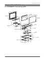
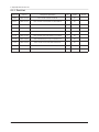
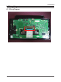
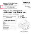
5. Exploded View & Part List
5. Exploded View & Part List
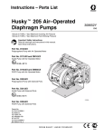
5-1. LP08PSMSB/XF - Exploded View (800P)
M0215
T0003
M0013
T0265
M0003
T0175
BN96-12518A
M0014
T0145
T0531
5-1
5. Exploded View & Part List
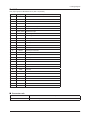
5-1-1. Part List
Location No.
Code No.
Description & Specification
Q’ty
SA/SNA
M0003
BN96-12120A
ASSY STAND P;SWAN 8",ABS,NI
1
SA
M0013
BN96-12121A
ASSY COVER P-REAR;SWAN 8",ABS,HB,BK23
1
SA
M0014
BN94-03171A
ASSY PCB MAIN-OTZ,W/W;LP08PSMSB/EN,W/W
1
SA
M0215
BN07-00761A
LCD-PANEL;AT080TN03,IN080038,6Bit Hi-FRC
1
SA
T0003
BN96-12119A
ASSY COVER P-FRONT;SWAN 8",ABS+PMMA,BLAC
1
SA
T0145
BN96-12124A
ASSY COVER P-BOTTOM;SWAN 8",PC CLEAR
1
SA
T0175
BN96-12068A
ASSY SPEAKER P;8ohm,2pin,0.7W,50mm,Unit
2
SA
T0265
BN96-12359A
ASSY COVER P-TOP;800P,ABS+PMMA,BK27
1
SA
T0531
BN63-06179A
COVER-BOTTOM;SWAN 8",PC CLEAR,TTP01
1
SA
BN96-12518A
ASSY BOARD P-KEY FUNCTION;P-PROJECT,1299
1
SA
5-2
Remark
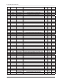
5. Exploded View & Part List
5-2. LP08PSMSB/XF - Part List (800P)
Service Bom (SA: SERVICE AVAILABLE, SNA: SERVICE NOT AVAILABLE)
Level
Location No.
0.1
Code No.
Description & Specification
Q’ty
SA/SNA
BN90-02345A
ASSY COVER FRONT;LP08PS,800P
1
SNA
T0003
BN96-12119A
ASSY COVER P-FRONT;SWAN 8",ABS+PMMA,BLAC
1
SA
...3
CCM1
BN63-02183K
COVER-SHEET;Rhcm,PE Vinyl,T 0.04,250MM,2
0.4
SNA
...3
M0112
BN63-06171A
COVER-FRONT;SWAN 8",PMMA, ABS+PMMA(BK23)
1
SNA
0.1
M0002
BN90-02346A
ASSY COVER REAR;LP08PS,800P
1
SNA
..2
M0013
BN96-12121A
ASSY COVER P-REAR;SWAN 8",ABS,HB,BK23
1
SA
...3
CCM1
BN63-02183K
COVER-SHEET;Rhcm,PE Vinyl,T 0.04,250MM,2
0.2
SNA
...3
M0006
BN63-06174A
COVER-REAR;SWAN 8",ABS,HB,BK23
1
SNA
BN91-04350T
ASSY LCD-OTZ;V2OIP
1
SNA
..2
0.1
..2
M0215
BN07-00761A
LCD-PANEL;AT080TN03,IN080038,6Bit Hi-FRC
1
SA
0.1
M0017
BN91-04468P
ASSY CHASSIS-OTZ,W/W;LP08PSMSB/EN
1
SNA
..2
M0014
BN94-03171A
ASSY PCB MAIN-OTZ,W/W;LP08PSMSB/EN,W/W
1
SA
...3
0202-001463
SOLDER-WIRE;LFC2-W3.0,-,D3,99.79Sn/0.2Cu
0.938
SNA
...3
0202-001608
SOLDER-WIRE FLUX;LFC7-107,D0.8,99.3Sn/0.
0.025
SNA
...3
0204-002420
SOLVENT;1M-1000,C3H70H,96
3.52
SNA
0204-002607
FLUX;DF-234U,13%,14KG,Gravity 0.82
2.287
SNA
BN97-03664R
ASSY SMD;LP08PSMSB/EN,BN41-01298A
1
SNA
...3
...3
T0174
....4
0202-001477
SOLDER-CREAM;LST309-M,D20~45um,96.5Sn/3A
4.518
SNA
....4
D1
0401-001099
DIODE-SWITCHING;1N4148WS,75V,150mA,SOD-3
4
SA
....4
D0254
0402-000553
DIODE-SCHOTTKY;SS24/B240,40V,2000mA,DO-2
1
SA
....4
MZD1
0403-001411
DIODE-ZENER;5.49-5.73V,200mW,SOD-323,TP
6
SA
0406-001181
DIODE-TVS;NUP4201MR6,6/-/-V,500W,TSOP-6
2
SA
....4
....4
Q409
0505-002234
FET-SILICON;PMV65XP,P,-20V,-3.9A,0.076oh
2
SA
....4
IC112
1103-000129
IC-EEPROM;24C02,2Kbit,256x8,SOP,8P,5x4mm
1
SA
1105-002030
IC-DDR SDRAM;NT5DS32M16CS-5T,DDR SDRAM,5
1
SA
....4
T0087
1203-002302
IC-POSI.FIXED REG.;78RM33D,D-PAK,3P,-,PL
1
SA
....4
T0087
1203-002842
IC-POSI.FIXED REG.;AP1117D-33,TO-252,3P,
2
SA
....4
T0087
1203-002974
IC-POSI.FIXED REG.;AP1117D-25A,TO-252,3P
1
SA
....4
T0087
1203-003696
IC-POSI.FIXED REG.;NCP1117DT18T5G,DPAK,3
1
SA
1203-005279
IC-DC/DC CONVERTER;MP2372DN,SOP,8P,4.9x3
1
SA
SA
....4
....4
....4
IC120
1205-002412
IC-TRANSMITTER;DTC34LM85A,TSSOP,56P,14x6
1
....4
P803T
1404-001470
THERMISTOR-PTC;0.15/0.75ohm,15V,100A,1.0
1
SA
1405-001232
VARISTOR;5.6Vdc,30A,1.6x0.8x0.8mm,TP
8
SNA
....4
....4
JP19
2007-000033
R-CHIP;0ohm,5%,1/4W,TP,3216
2
SNA
....4
DR1
2007-000043
R-CHIP;1Kohm,1%,1/10W,TP,1608
3
SA
....4
PR4
2007-000052
R-CHIP;10Kohm,1%,1/10W,TP,1608
2
SNA
....4
KAR13
2007-000060
R-CHIP;100Kohm,1%,1/10W,TP,1608
5
SNA
....4
ND51C2
2007-000066
R-CHIP;20Kohm,1%,1/10W,TP,1608
1
SNA
....4
KAR21
2007-000070
R-CHIP;0ohm,5%,1/10W,TP,1608
49
SNA
....4
CER02
2007-000071
R-CHIP;22ohm,5%,1/10W,TP,1608
10
SNA
....4
AR164
2007-000076
R-CHIP;330ohm,5%,1/10W,TP,1608
1
SA
....4
FMR4
2007-000080
R-CHIP;2Kohm,5%,1/10W,TP,1608
3
SNA
....4
CER04
2007-000084
R-CHIP;4.7Kohm,5%,1/10W,TP,1608
11
SA
....4
MROP1
2007-000090
R-CHIP;10Kohm,5%,1/10W,TP,1608
23
SA
....4
MR13
2007-000092
R-CHIP;15Kohm,5%,1/10W,TP,1608
3
SA
Remark
5-3
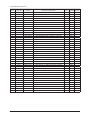
5. Exploded View & Part List
Level
Location No.
Code No.
Description & Specification
Q’ty
SA/SNA
....4
KAR9
2007-000093
R-CHIP;20Kohm,5%,1/10W,TP,1608
1
SNA
....4
ZR24
2007-000109
R-CHIP;1Mohm,5%,1/10W,TP,1608
2
SNA
....4
DR10
2007-000113
R-CHIP;33ohm,5%,1/10W,TP,1608
14
SNA
....4
KAR11
2007-000124
R-CHIP;2.2Kohm,5%,1/10W,TP,1608
3
SNA
....4
R111
2007-000171
R-CHIP;0ohm,5%,1/16W,TP,1005
24
SNA
....4
R1035
2007-000287
R-CHIP;100ohm,1%,1/10W,TP,1608
1
SNA
....4
MR9
2007-000455
R-CHIP;18Kohm,1%,1/10W,TP,1608
1
SA
2007-000606
R-CHIP;240ohm,1%,1/10W,TP,1608
1
SA
....4
....4
AR61
2007-000869
R-CHIP;4.7Kohm,1%,1/10W,TP,1608
1
SNA
....4
R1
2007-002425
R-CHIP;1ohm,5%,1/10W,TP,1608
18
SNA
....4
DAR09
2011-001262
R-NETWORK;22ohm,5%,1/16W,L,CHIP,8P,TP,2.
10
SA
....4
AC14
2203-000189
C-CER,CHIP;100nF,+80-20%,25V,Y5V,TP,1608
64
SNA
....4
C134
2203-000257
C-CER,CHIP;10nF,10%,50V,X7R,TP,1608
4
SA
....4
C212
2203-000440
C-CER,CHIP;1nF,10%,50V,X7R,1608
4
SA
....4
ZC14
2203-000626
C-CER,CHIP;0.022nF,5%,50V,C0G,1608
9
SNA
....4
ZC165
2203-000815
C-CER,CHIP;0.033nF,5%,50V,C0G,1608
2
SA
....4
AAC14
2203-000888
C-CER,CHIP;4.7nF,10%,50V,X7R,TP,1608
1
SA
....4
AC124
2203-000998
C-CER,CHIP;0.047nF,5%,50V,C0G,1608
1
SNA
....4
UC12
2203-001083
C-CER,CHIP;0.0050nF,0.1pF,50V,NP0,1608
2
SA
....4
AC28
2203-001607
C-CER,CHIP;0.22nF,5%,50V,NP0,1608
4
SA
....4
EC14
2203-001724
C-CER,CHIP;4700nF,+80-20%,16V,Y5V,TP,321
1
SNA
....4
DC108
2203-005005
C-CER,CHIP;100nF,10%,16V,X7R,1608
18
SC
....4
C410
2203-005384
C-CER,CHIP;4700nF,+80-20%,10V,Y5V,TP,201
2
SNA
....4
AD480
2203-005437
C-CER,CHIP;10000nF,+80-20%,10V,Y5V,3216
1
SNA
....4
AD480
2203-005809
C-CER,CHIP;1000nF,10%,16V,X7R,TP,2012
4
SC
....4
EC9
2203-005834
C-CER,CHIP;22000nF,+80-20%,10V,Y5V,3216
6
SA
....4
AD480
2203-006024
C-CER,CHIP;2200nF,10%,10V,X7R,2012
2
SNA
....4
C102
2203-006158
C-CER,CHIP;100nF,10%,16V,X7R,1005
4
SNA
....4
AD480
2203-006333
C-CER,CHIP;10000nF,20%,16V,X5R,TP,3216
27
SNA
....4
AD480
2203-006336
C-CER,CHIP;10000nF,10%,25V,X5R,3216
3
SA
....4
AD480
2203-007233
C-CER,CHIP;22000nF,10%,16V,X5R,TP,3216
1
SA
2409-001168
C-EDL;200000uF,3.3V,0.01mA,TP,D6.8x11.3m
1
SA
....4
....4
X202
2801-000258
CRYSTAL-SMD;0.032768MHz,20ppm,SMD,12.5pF
1
SA
....4
XD01
2801-004164
CRYSTAL-SMD;12MHZ,50PPM,28-ACI,7PF,100OH
1
SA
....4
X202
2801-004355
CRYSTAL-SMD;13.5MHz,30ppm,28-AAN,20,40oh
1
SA
....4
L2011
3301-001145
BEAD-SMD;60ohm,4516,TP,70ohm/45MHz,82ohm
2
SNA
....4
T0568
3301-001393
BEAD-SMD;60ohm,3216,1500mA,TP,41ohm/40MH
15
SNA
....4
T0568
3301-001404
BEAD-SMD;30ohm,2012,TP,15.9OHM/30MHz
6
SA
....4
T0568
3301-001407
BEAD-SMD;30ohm,1608,300mA,TP,,,0.4ohm
4
SNA
....4
T0568
3301-001594
BEAD-SMD;90ohm,2.0*1.2*1.3mm,TP,-,-
7
SNA
3601-001376
FUSE-SURFACE MOUNT;32V,3A,FAST-ACTING,Hi
1
SA
....4
....4
3708-001150
CONNECTOR-FPC/FFC/PIC;30P,1mm,SMD-A,SN,Y
1
SA
....4
3709-001579
CONNECTOR-CARD EDGE;14,2.5mm,SMD-A,Au,SD
1
SA
....4
3711-005509
HEADER-BOARD TO CABLE;BOX,4P,1R,1.25mm,S
2
SA
....4
3711-005743
HEADER-BOARD TO CABLE;BOX,5P,1R,1.25mm,A
1
SA
....4
3722-002528
JACK-USB;5P,AU30U,BLK,SMD-A,MINI USB B
1
SA
....4
3722-002894
JACK-USB;4P,Au 30/ Ni 80,BLK,SMD-A,A-TYP
1
SA
....4
3722-002895
JACK-DC POWER;2P,4.4PI,nickel,black
1
SA
BN27-00007A
COIL CHOKE-SMD;DHB0504-100,RB15/17NS,10u
1
SA
....4
5-4
AC510
T0010
Remark
5. Exploded View & Part List
Level
Location No.
Code No.
Description & Specification
Q’ty
SA/SNA
....4
T0077
BN41-01270A
PCB MAIN;P,FR-4,4,1.2,191X128mm,1
1
SNA
....4
BN97-03853C
ASSY MICOM-MAIN(2G),OTZ,W/W;LP08PSMSB/*,
1
SNA
.....5
1107-001864
IC-NAND FLASH;K9GAG08U0D-PCB0,2GByte,2Gx
1
SA
SNA
BN97-03853D
ASSY MICOM-SUB,OTZ,W/W;LP08PSMSB/*,BN41-
1
.....5
....4
IC520
0903-001624
IC-MICROCONTROLLER;WT6703F,SSOP,24P,8.7x
1
SA
....4
J914
2007-000029
R-CHIP;0ohm,5%,1/8W,TP,2012
1
SC
....4
4202-001511
ANTENNA-CHIP;2400~2500,2450MHz,3dB,less
1
SNA
....4
4709-001810
BLUETOOTH MODULE;26MHz,Bluetooth Module,
1
SA
....4
D0254
0609-001367
MODULE REMOCON;SMD-V,1.35mm,TP
1
SNA
....4
IC520
0903-001612
IC-MICROCONTROLLER;SK8855BBPVC,LQFP,256P
1
SA
....4
1204-003099
IC-MODULATOR;451M-16,SOIC,8P,5x6.2x1.75m
1
SA
....4
1205-003860
IC-CODEC;ALC5626-GR,QFN,32P,5x5x0.85mm,3
1
SA
3722-002969
JACK-EAR PHONE;5P,AU,BLK,SMD-A
1
SA
0909-001032
IC-REAL TIME CLOCK;PCF8563,SOP,8P,4.9x3.
1
SA
....4
....4
IC105
....4
1405-001233
VARISTOR;30Vdc,5A,1.6x0.8x0.8mm,TP
1
SA
....4
Q613
0501-000465
TR-SMALL SIGNAL;MMBT3904,NPN,350mW,SOT-2
1
SA
....4
HR12
2007-000591
R-CHIP;22ohm,1%,1/10W,TP,1608
2
SNA
2007-000736
R-CHIP;30Kohm,1%,1/10W,TP,1608
1
SA
2007-002899
R-CHIP;10ohm,1%,1/10W,TP,1608
1
SA
....4
....4
ER19
....4
2007-007229
R-CHIP;360ohm,1%,1/10W,TP,1608
1
SA
....4
AD480
2203-002668
C-CER,CHIP;0.0005nF,0.1pF,50V,NP0,TP,100
1
SA
....4
T0052
2703-001737
INDUCTOR-SMD;2.7nH,0.3nH,1005
1
SNA
....4
T0052
2703-001747
INDUCTOR-SMD;4.7nH,0.3nH,1005
1
SA
....4
T0052
....4
.....5
IC112
0.1
2703-002365
INDUCTOR-SMD;1.2nH,0.3nH,1005
1
SA
BN97-03927V
ASSY MICOM-EPROM_W/W;P,BN41-*
1
SNA
1103-001223
IC-EEPROM;24C16,16Kbit,2Kx8,SOP,8P,5x4mm
1
SA
BN91-04551A
ASSY SHIELD;LP08PS,800P
1
SNA
SCREW-TAPTYPE;BH,+,B,M2,L6,ZPC(BLK)
5
SA
..2
M0081
6003-001438
..2
T0175
BN96-12068A
ASSY SPEAKER P;8ohm,2pin,0.7W,50mm,Unit
2
SA
..2
T0145
BN96-12124A
ASSY COVER P-BOTTOM;SWAN 8",PC CLEAR
1
SA
...3
T0531
BN63-06179A
COVER-BOTTOM;SWAN 8",PC CLEAR,TTP01
1
SA
...3
T0069
BN63-06180A
COVER-MIDDLE;SWAN 8",ABS,HB,WH13
1
SNA
...3
AS501
AH61-02950A
STAND-FOOT;ht-sb1,rubber,2.0,5,5,white
2
SNA
...3
CCM1
BN63-02183K
COVER-SHEET;Rhcm,PE Vinyl,T 0.04,250MM,2
0.2
SNA
...3
M0126
BN73-00170C
RUBBER-FOOT;943BW,2043BW,RUBBER,8*8,3.0,
1
SNA
..2
T0265
BN96-12359A
ASSY COVER P-TOP;800P,ABS+PMMA,BK27
1
SA
...3
BN61-05862A
GUIDE-PCB;SWAN 8",ABS,WH13
1
SNA
...3
AC310
BN63-06176A
COVER-TOP;SWAN 8",ABS+PMMA,BK27
1
SNA
...3
AS078
BN63-06182A
SHEET-FUNCTION;SWAN 8",PC SHEET,0.1T,BLA
1
SNA
BN96-12518A
ASSY BOARD P-KEY FUNCTION;P-PROJECT,1299
1
SA
CCM1
BN63-05199D
COVER-SHEET;AMBER,PE,T0.08,W75mm,200M,CL
0.25
SNA
0203-005051
TAPE-CONDUCTIVE;EMTS-20-0.2-65,Polyester
2
SA
..2
M0003
BN96-12120A
ASSY STAND P;SWAN 8",ABS,NI
1
SA
...3
T0056
...3
...3
..2
BN63-06170A
COVER-DECORATION;SWAN 8",ABS,HB,NI
1
SNA
...3
BN63-06172A
COVER-DECORATION SUB;SWAN 8",ABS,HB,NI
1
SNA
...3
BN63-06173A
COVER HINGE-FRONT;SWAN 8",ABS,HB,BN63-06
1
SNA
...3
BN63-06175A
COVER HINGE-REAR;SWAN 8",ABS,HB,SILVER S
1
SNA
...3
T0054
BN96-12122A
ASSY HINGE P;SWAN 8",SK-5
1
SNA
...3
M0230
BN96-12447A
ASSY CABLE P-FFC;P-Project,FFC,255mm,30P
1
SA
...3
S0F0122
6003-001446
SCREW-TAPTYPE;BH,+,M2,L5,NI PLT,SWRCH18A
6
SNA
Remark
5-5
5. Exploded View & Part List
Level
Location No.
Code No.
Description & Specification
Q’ty
SA/SNA
..2
BN63-06411A
SHEET-PANEL W;800P,PORON,0.3T,3,188,blac
2
SNA
..2
BN63-06412A
SHEET-PANEL L;800P,PORON,0.3T,3,114,blac
2
SNA
..2
BN63-06556A
SHEET-PROTECTOR;800P,PET,0.1,224,147
1
SNA
..2
S0F0122
6003-001446
SCREW-TAPTYPE;BH,+,M2,L5,NI PLT,SWRCH18A
5
SNA
..2
CCM1
BN63-02183K
COVER-SHEET;Rhcm,PE Vinyl,T 0.04,250MM,2
0.2
SNA
..2
T0073
AA63-01110C
GASKET-EMI;42D5,1.0,10,22,45Kg/m2,Fabric
1
SNA
..2
CIS1
0.1
..2
CCM1
BN74-00021A
TAPE-FILAMENT;Filament tape,clear,#8915,
0.06
SNA
BN92-02839V
ASSY LABEL;LP08CPLSS/EDC
1
SNA
BN68-01316A
LABEL RATING;WW,SS,PET POLYESTER,0.05,60
1
SNA
0.1
BN92-05368K
ASSY P/MATERIAL;LP08PSMSB/EN
1
SNA
..2
6902-000061
BAG AIR;LDPE,T0.2,W500,L1000,TRP,370.000
1
SNA
..2
6902-000379
BAG AIR;LDPE,T0.2,W1000,L1800,TRP,1260.0
1
SNA
..2
6902-000604
BAG WRAPPING;LDPE,T0.02,W500,L10000,TRP,
0.14
SNA
..2
6902-000609
BAG ROLL;LDPE,T0.05,W2400,L1000,TRP,30.0
0.01
SNA
..2
T0527
BH68-40364A
LABEL-SUMMARY;G52,G72,ART,100G,WHT,BLK,W
1
SNA
..2
T0527
BN68-00129A
LABEL SHIPPING-00;LABEL SHIPPING,ART-PAP
1
SNA
..2
BN68-02398A
LABEL-01,SEALING;E5(E-BOOK),art paper,w5
1
SNA
..2
BN69-00391Y
PAD-ANGLE;CB,T5,W2100,L50,YEL,403g
1
SNA
..2
BN69-04231A
CUSHION-BLISTER-BOT;800P,PS
1
SNA
0203-001269
TAPE-OPP MASKING;#301,T0.06,W75,L50000,N
0.14
SNA
BN69-04342A
CUSHION-BLISTER TOP;800P,PET,0.5
1
SNA
..2
T0214
..2
..2
AA69-03219H
PAD-PLATE;CB SW-2,1040,900
1
SNA
..2
BH69-00457D
PACKING-PAD;CY15PO,T3.0,0g
1
SNA
BN69-01058E
PALLET-PACKING;LS19VIP,WOOD-WoodEN,1040,
1
SNA
6902-000389
BAG PE;HDPE/NITRON/HDPE,T0.015/T0.5/T0.0
1
SNA
..2
..2
T0524
0.1
BN92-05391K
ASSY BOX;LP08PSMSB/EN
1
SNA
..2
BH68-20015B
LABEL BAR CODE-00;ALL MODEL,MOJO 90G,90,
1
SNA
BN68-00134L
LABEL-BOX,01;ALL MODEL,MOJO 90G,120X90,W
1
SNA
..2
BN69-04227A
BOX-02,SET;800P,CB,NON-STANDARD,W828.5,D
1
SNA
..2
BN69-04228A
BOX-01,MASTER;800P,CB,A-01,W522,D437,H23
1
SNA
..2
T0527
0.1
M0045
BN92-05471U
ASSY ACCESSORY;LP08PSMSB/XF
1
SNA
..2
T0268
3903-000381
CBF-POWER CORD;DT,CHINA,LSG-21,250/250V,
1
SA
..2
T0527
AA68-00764A
LABEL-PASSING;SAMSUNG ALL,ART PAPER,CLR,
1
SNA
..2
M0158
BN44-00133C
ADAPTOR;SAD1212,IPANEMA/SWAN,110/230V,50
1
SA
..2
BN59-00970A
S/W DRIVER-02,IB;800P,1000P,22Lang,Samsu
1
SNA
..2
T0074
BN59-00980A
REMOCON;TM920,20PIN,15,ALBUM
1
SA
..2
M9889
BN63-02368B
CLOTH-CLEAN;cloth,120,160,sea blue,ToC
1
SNA
BN68-01789A
MANUAL FLYER-WARRANTY CARD;Chinese,Art 1
1
SNA
..2
BN68-02186A
MANUAL FLYER-TOC GUIDE;COMM,SAMSUNG,10 L
1
SNA
..2
BN68-02399B
MANUAL FLYER-QSG;800P,1000P,Samsung,5 La
1
SNA
GK39-00013B
CBF INTERFACE-USB;MYGENIE(DMB 10"),4P/5P
1
SC
..2
..2
5-6
T0725
Remark
1. Precautions
1. Precautions
1-1. Safety Precautions
Follow these safety, servicing and ESD precautions to prevent damage and to protect against potential hazards such as
electrical shock.
1-1-1. Warnings
1. For continued safety, do not attempt to modify the circuit board.
2. Disconnect the AC power and DC power jack before servicing.
1-1-2. Servicing the LCD Monitor
1. When servicing the LCD Monitor, Disconnect the AC line cord from the AC outlet.
2. It is essential that service technicians have an accurate voltage meter available at all times. Check the calibration of
this meter periodically.
1-1-3. Fire and Shock Hazard
Before returning the monitor to the user, perform the following safety checks:
1. Inspect each lead dress to make certain that the leads are not pinched or that hardware is not lodged between the
chassis and other metal parts in the monitor.
2. Inspect all protective devices such as nonmetallic control knobs, insulating materials, cabinet backs, adjustment and
compartment covers or shields, isolation resistorcapacitor networks, mechanical insulators, etc.
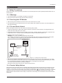
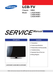
3. Leakage Current Hot Check (Figure 1-1):
WARNING : Do not use an isolation transformer during this test.
Use a leakage current tester or a metering system that complies with American National Standards Institute (ANSI
C101.1, Leakage Current for Appliances), and Underwriters Laboratories (UL Publication UL1410, 59.7).
(READING SHOULD)
NOT BE ABOVE 0.5mA
LEAKAGE
CURRENT
TESTER
DEVICE
UNDER
TEST
TEST ALL
EXPOSED METAL
SURFACES
2-WIRE CORD
*ALSO TEST WITH
PLUG REVERSED
(USING AC ADAPTER
PLUG AS REQUIRED)
EARTH
GROUND
Figure 1-1. Leakage Current Test Circuit
4. With the unit completely reassembled, plug the AC line cord directly into a 120V AC outlet. With the unit’s AC switch
first in the ON position and then OFF, measure the current between a known earth ground (metal water pipe, conduit,
etc.) and all exposed metal parts, including: metal cabinets, screwheads and control shafts.
The current measured should not exceed 0.5 milliamp.
Reverse the power-plug prongs in the AC outlet and repeat the test.
1-1-4. Product Safety Notices
Some electrical and mechanical parts have special safetyrelated characteristics which are often not evident from visual
inspection. The protection they give may not be obtained by replacing them with components rated for higher voltage,
wattage, etc. Parts that have special safety characteristics are identified by
on schematics and parts lists. A substitute
replacement that does not have the same safety characteristics as the recommended replacement part might create
shock, fire and/or other hazards. Product safety is under review continuously and new instructions are issued whenever
appropriate.
1-1
1. Precautions
1-2. Servicing Precautions
WARNING: An electrolytic capacitor installed with the wrong polarity might explode.
Caution:
Before servicing units covered by this service manual, read and follow the Safety Precautions section of
this manual.
Note:
If unforeseen circumstances create conflict between the following servicing precautions and any of the
safety precautions, always follow the safety precautions.
1-2-1 General Servicing Precautions
1. Always unplug the unit’s AC power cord from the AC power source and disconnect the DC Power Jack before
attempting to:
(a) remove or reinstall any component or assembly, (b) disconnect PCB plugs or connectors, (c) connect a test
component in parallel with an electrolytic capacitor.
2. Some components are raised above the printed circuit board for safety. An insulation tube or tape is sometimes
used. The internal wiring is sometimes clamped to prevent contact with thermally hot components. Reinstall all such
elements to their original position.
3. After servicing, always check that the screws, components and wiring have been correctly reinstalled. Make sure that
the area around the serviced part has not been damaged.
4. Check the insulation between the blades of the AC plug and accessible conductive parts (examples: metal panels,
input terminals and earphone jacks).
5. Insulation Checking Procedure: Disconnect the power cord from the AC source and turn the power switch ON.
Connect an insulation resistance meter (500 V) to theblades of the AC plug.
The insulation resistance between each blade of the AC plug and accessible conductive parts (see above) should be
greater than 1 megohm.
6. Always connect a test instrument’s ground lead to the instrument chassis ground before connecting the positive lead;
always remove the instrument’s ground lead last.
1-3. Static Electricity Precautions
Some semiconductor (solid state) devices can be easily damaged by static electricity. Such components are commonly
called Electrostatically Sensitive Devices (ESD). Examples of typical ESD are integrated circuits and some field-effect
transistors. The following techniques will reduce the incidence of component damage caused by static electricity.
1. Immediately before handling any semiconductor components or assemblies, drain the electrostatic charge from your
body by touching a known earth ground. Alternatively, wear a discharging wrist-strap device. To avoid a shock hazard,
be sure to remove the wrist strap before applying power to the monitor.
2. After removing an ESD-equipped assembly, place it on a conductive surface such as aluminum foil to prevent
accumulation of an electrostatic charge.
3. Do not use freon-propelled chemicals. These can generate electrical charges sufficient to damage ESDs.
4. Use only a grounded-tip soldering iron to solder or desolder ESDs.
5. Use only an anti-static solder removal device. Some solder removal devices not classified as “anti-static” can generate
electrical charges sufficient to damage ESDs.
6. Do not remove a replacement ESD from its protective package until you are ready to install it. Most replacement ESDs
are packaged with leads that are electrically shorted together by conductive foam, aluminum foil or other conductive
materials.
7. Immediately before removing the protective material from the leads of a replacement ESD, touch the protective
material to the chassis or circuit assembly into which the device will be installed.
Caution: Be sure no power is applied to the chassis or circuit and observe all other safety precautions.
8. Minimize body motions when handling unpackaged replacement ESDs. Motions such as brushing clothes together,
or lifting your foot from a carpeted floor can generate enough static electricity to damage an ESD.
1-2
1. Precautions
1-4. Installation Precautions
1. For safety reasons, more than two people are required for carrying the product.
2. Keep the power cord away from any heat emitting devices, as a melted covering may cause fire or electric shock.
3. Do not place the product in areas with poor ventilation such as a bookshelf or closet. The increased internal
temperature may cause fire.
4. Make sure to turn the power off and unplug the power cord from the outlet before repositioning the product. Also check
the antenna cable or the external connectors if they are fully unplugged. Damage to the cord may cause fire or electric
shock.
5. Keep the antenna far away from any high-voltage cables and install it firmly. Contact with the highvoltage cable or the
antenna falling over may cause fire or electric shock.
6. When installing the product, leave enough space (10cm ( 3.937 inch)) between the product and the wall for ventilation
purposes.
A rise in temperature within the product may cause fire.
1-3
1. Precautions
Memo
1-4
2. Product specifications
2. Product specifications
2-1. Feature & Specifications
Model
800P / 1000P
Feature
ሪሪ Display JPEG and BMP format pictures.
ሪሪ PLAY MP3 format music files.
ሪሪ PLAY MPEG1,4,M-JPEG format video files.
ሪሪ Support various slideshow effect with adjustable time interval.
ሪሪ Stylish design.
ሪሪ Supports various types of memory cards. (SD and USB memory device)
ሪሪ Provides date and time display.
ሪሪ Easy user interface (remote controller, touch key)
Specifications
Panel
Model
800P
1000P
Type
8” TFT LCD / Innolux
10” TFT LCD / Hannstar
Resolution
800 x 480
1024 x 600
Brightness
230cd/m2
230cd/m2
Contrast Ratio
300:1
500:1
Viewing Angle
45/65/65/65 (U/D/L/R)
50/60/70/70 (U/D/L/R)
Interface
Response Time
Contents Format
Storage
Digital LVDS
35 msec (Tr+Tf)
25 msec (Tr+Tf)
Picture : BMP, JPEG
support to Progressive JPEG , except CMYK
support to under 8000X8000 resolution file
Music : MP3(resolution: 8~48KHz,Bit Rates : 8~320KBps)
Video : MPEG1 (resolution: 720 X 480, Bit Rates : 2 Mbps)
MPEG4 (resolution: 720 X 480, Bit Rates : 2 Mbps)
M-JPEG (resolution: 640 X 480, Bit Rates : 15 Mbps)
Flash Memory
100MB (Code) + 1900 MB (User)
Main Memory
64MB SDRAM
USB
Host (USB2.0), Slave (USB2.0)
Media
SD,USB
Browse Contents
Slideshow (Transition, Speed, Mode, Order..etc), View Mode, Aspect Ratio,
Display Photo Info
Control
I/O Device
Remote Control, Touch Key (10 buttons)
File Management
Copy, Delete
Dimensions
(W x D x H)
228.0 x 193.4 x 27.0 mm (SET)
228 x 224 x 82 mm (Package)
272.0 x 223.6 x 27.0 mm (SET)
302 x 254 x 82 mm (Package)
Weight
500g
600g
2-1
2. Product specifications
2-2. Spec Comparison to the Old Models
Model
800P / 1000P
IPANEMA (SPF-87H / SPF-107H)
Penel Type
8” TFT LCD / Innolux
10” TFT LCD / Hannstar
8” TFT LCD / Hannstar
10” TFT LCD / Hannstar
Resolution
8” 800 x 480
10” 1024 x 600
8” 800 x 480
10” 1024 x 600
8” 35 msec
10” 25 msec
20 ms
8” 230 cd/m2
10” 230cd/m2
200 cd/m2 (SPF-87H)
250 cd/m2 (SPF-107H)
Contrast Ratio
8” 300:1
10” 500:1
500:1
Viewing Angle
8” 45/65/65/65 (U/D/L/R)
10” 50/60/70/70 (U/D/L/R)
50 / 60 / 70 / 70 (U / D / L / R)
Black
Black / Red
JPG, BMP, MP3, MPEG1, MPEG4, MJPG
JPG
2GB
1GB
Design
Response Time
Brightness
Color
Support Contents
Format
Internal Memory
2-2
2. Product specifications
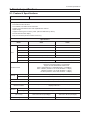
2-3. Accessories
Product
Description
Ccde. No
Remote Control
BN59-00980A
Power Cord
3903-000382
Adapter
BN44-00133C
USB Cable
GK39-00013B
Quick Start Guide
and Warranty
BN68-00226R
CD-ROM
(User Manual)
BN68-02399A
Cloth
BN63-02368B
Remark
Samsung Electronics
Service center
2-4. Accessories (Sold Separately)
Product
Description
Type Quantity
SD
SD (Max 2G), microSD (Max 2GB),
miniSD (Max 256MB), SDHC (Max 16GB),
microSDHC (Max 8G)
2-3
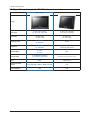
2. Product specifications
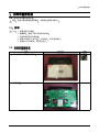
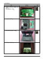
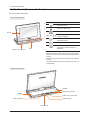
2-5. The Control Panel and Its Functions
ሪሪ Function Button Descriptions
The front of your frame
Touch button*
Description
Turn the frame on; Turn the frame off
(touch and hold)
Access the Main menu
Access menus
Screen
Scroll through menus or items
(up/down/left/right)
Select menus or items; Perform
selected functions
Base
Return to the previous level
Play a slideshow in an any screen;
Remote control sensor
Change the view mode during a
Base
slideshow
When using the touch buttons
• Operate the touch buttons only with your fingers. Make
sure your hands are clean and dry when using the touch
buttons.
• Lightly touch the button that corresponds to the desired
function.
• The touch sensor may not work properly when wet or in
humid places.
The rear of your frame
Speaker
SD memory card slot
Speaker
USB memory device port
Power cable port
USB cable port
Headset port
2-4
2. Product specifications
Remote control
Button
Description
Turn the frame on or off
Access the Main menu
Access menus
Return to the previous level
Scroll through menus or items (up/
down/left/right)
Select menus or items
Play a slideshow in any screen;
Change the view mode during a
slideshow
View the time and date
Open the battery cover by turning to the left,
replace the battery, and close the battery cover by
Rotate a photo during a slideshow
turning to the right.
Access the photo list screen
Access the music list screen
Access the video list screen
2-5
2. Product specifications
ሪሪ OSD Menu Structure
Use the buttons on the back of the product to set various functions to your preferences.
Browse photos stored in the internal memory or on an external memory device and change options
Home
Copy
Photo
Delete
Select Multiple
Files
Select Storage
Device
Settings
Moves to the main screen
If an external memory device (SD memory card/ USB memory device) is connected to the
product,
• Copies pictures in an external memory device to the internal memory
• Copies pictures in the internal memory to an external memory device
Deletes pictures in the internal memory or an external memory device
Selects multiple files to run functions like slide show, copy, delete, etc.
If an external memory device (SD memory card/USB memory device) is connected to the
product ,
• Select the internal memory or an external memory device (SD memory card/USB
memory device)
Music
Listen to music stored in the internal memory or on an external memory device and change options
Videos
View videos stored in the internal memory or on an external memory device and change options
Use the Bluetooth wireless feature to connect to other wireless devices
Bluetooth
Photo List
Access the photo list of the paired device
Rename
Rename the paired device
Delete
Delete one of the paired devices
Delete All
Delete all of the paired devices
Settings
Access the Settings menu
View the current time and date
Clock
Mini
Monitor
Clock Set
Set the current time and date
Date Format
Select how dates display (YYYY. MM. DD, MM. DD. YYYY, DD. MM. YYYY)
Time Format
Select how time displays (12 Hours, 24 Hours)
View Mode
Select the clock type (Clock Only, Clock + Calendar)
Use the frame as a supplementary monitor for your PC
Read the Frame Manager User Manual to install the program properly. Use the USB cable provided with the
frame.
Simple Settings
Language
Brightness
Auto Screen On/
Off Setting
2-6
Sets the screen to automatically turn on and off at certain times
Selects the screen to be displayed when the digital frame is switched on
• Home / Last Used Mode / Slide Show
• Original Copy Size: Copies an original file as is
Copy Internal
• Optimal Size: Matches the screen’s optimal resolution by reducing the file
Memory
size and then copies.
Selects the recognition mode to be used when the digital frame is connected
a PC with a USB cable
USB Connection to
Use as a removable disk or mini monitor
Use as a digital photo frame
Software Upgrade Updates the firmware
Resets user-customized menu options to default
Reset Settings
(Time setting and screen language setting excluded)
Customer
Product
Support
Product functions guide
Introduction
Product
Displays product model name, firmware version, internal memory and
Information
copyrights
General
Settings
Settings
Easy settings for frequently used functions
(Viewing Mode, Slide Show Effect, Time Setting Mode and Start Mode)
Selects the OSD (on-screen display) language
Adjusts the screen brightness
Start Mode
! " #$
%&'
()*+,-
./
#$
()*+,-
01%2
!
"#
./
#$
()*+,-
34%2
!
$ %
$ "#
#$
()*+,-
56()
%&
'()*'+,- )*./
!"!##
####
0123
45"# #$
78"9:;<
=>2'?
@A'?B:C D&E FGHIJK"LMNJ
O 0PQR'? HIJKLMN ST>UV() &EWXYZLMN[\ O]0P^_T`aWbcdVec fg 0PT`aWhijk =Nlmn opOq=r:C
YstuFvw'()
{'?tuF xyrzopOq
@
2'?| }~Oq
Y
WY
}~Oq
pFO !
=>r ¡¢[£ ¤kpF ¥B T>¦§¡¢=>
[£ ¨©ªpF|r« O
¤k±
! T>}~Y²Oq³´±
¬®O¯°±
~@A¶po·:C»«G¼¨©ª µW¶po· o·
¸ =>¹º ~@A¡¢µW¶po·½
¡¢¾¿IÀ
G=>0½
=Á{µ¶Âà »«¼Äo· B É ¡ ¢ ` Ê g Ë Ì ¨ © Í
ÅÆ
ÇÈ
ÎE
ÏÐF !" #$% !ÑÒ
¢ÏÐ|T>=B:¿ LMNÏÐ
r
Ӫɨ© @ ÔÕ»« Y²
=>ºÉÖ×
ÓáO
âãUVäª
Éå0Pæç
âãèéÓêÝ
&Ý '&Ý ëáäª
aìíBÇÈÅÆîï
ØdÙTÚ
ÛEÕÜÝ
G=>B
Þß ÔàG=>ºÉÖ×
ðÖ×0 ñò [óW(op)'(
)'(
0P) ÔôopÉ(äôÉõöâã)Ôrz[
\ ÷øE°
÷øâã
"ùúû
OT>üý¯° þ¸½åY
`Ö×
jk
cÿ¸½¼Ä
TÖ×
É@0 Ö×
jkGëá Õ=É() `*¸
𱡢
* Ö×
Ï
I"I ` çI·¡¢
=TÞß #$
Ö×=>ëáö
78"9:;<
@A(op) ' (&op)½(ö©)BopÉ(Ö
×) @ADOqop:C µÎopå(ëá0P*)0P=>ëá
D(ëá0P*)Bop| ¤kHIJK'
? 0PG=>[\ëá ëá0PO
qO '?B 0Pëá2 F ¸½
Wp
F| "¡¢âãUVäô DÄBWpFO ØdÙ¡¢
âãUVäô` W0P!" G#$%¢W ¸ T` +++ #, -%./, ´#$%¢&'(
G¸ )óHIJKS*Y½ +,opñò 0 +,Á{ +,&'Ò¢ 1 +,-%¢¸ D)óHIJK.¸/
2 +,0&' [Ý1230P &'E(½=~G¸4
& D56&'O Ôrz2á78
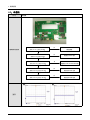
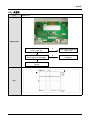
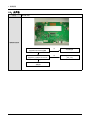
6. Wiring Diagram
6. Wiring Diagram
6-1. Wiring Diagram
6-1
6. Wiring Diagram
6-2. Pin Assignment
800P
LVDS Connector is used for the module electronics interface. The recommended model
is MDF76KBW-30S-1H(58) manufactured by Hirose.
Pin No.
Signal
I/O
1
VCC
P
Power voltage for digital circuit
2
VCC
P
Power voltage for digital circuit
3
VCC
P
Power voltage for digital circuit
4
U/D
I
Select up or down scanning direction
5
L/R
I
Select left to right scanning direction
6
VSS
P
Ground
7
VSS
P
Ground
8
Rin0-
I
- LVDS differential data input (R0-R5,G0)
9
Rin0+
I
+ LVDS differential data input (R0-R5,G0)
10
VSS
P
Ground
11
Rin1-
I
- LVDS differential data input (G1-G5,B0-B1)
12
Rin1+
I
+ LVDS differential data input (G1-G5,B0-B1)
13
VSS
P
Ground
14
Rin2-
I
- LVDS differential data input (B2-B5,HS,VS,DE)
15
Rin2+
I
+ LVDS differential data input (B2-B5,HS,VS,DE)
16
VSS
P
Ground
17
ClkIN-
I
-LVDS differential clock input
18
ClkIN+
I
+LVDS differential clock input
19
VSS
P
Ground
20
Rin3-
I
- LVDS differential data input (R6-R7,G6-G7,B6-B7)
21
Rin3+
I
+ LVDS differential data input (R6-R7,G6-G7,B6-B7)
22
VSS
P
Ground
23
VLED
P
Power voltage for LED circuit
24
VLED
P
Power voltage for LED circuit
25
GLED
P
Ground for LED circuit
26
GLED
P
Ground for LED circuit
27
NC
—
No Connection
28
NC
—
No Connection
29
ADJ
P
Adjust the Back Light brightness
30
DTH
P
Dithering function
6-2
Description
6. Wiring Diagram
1000P
CN1 (Input signal): FI-XB30SSRL-HF16 (JAE or equivalent)
Pin No.
Signal
Description
1
GND
Ground
2
VDD
3.3V Power
3
VDD
3.3V Power
4
V_EDID
5
ADJ
6
CLK_EDID
EDID Clock Input
7
DATA_EDID
EDID Data Input
8
RXIN0-
LVDS Signal - channel0-
9
RXIN0+
LVDS Signal+ channel0+
10
GND
11
RXIN1-
Data Input channel1-
12
RXIN1+
Data Input channel1+
13
GND
14
RXIN2-
Data Input channel2-
15
RXIN2+
Data Input channel2+
16
GND
17
RXCLKIN-
Data Input CLK-
18
RXCLKIN+
Data Input CLK+
19
GND
20
NC
NC
21
NC
NC
22
GND
Ground
23
GND
Ground
24
VLED
LED Power +5V
25
VLED
LED Power +5V
26
VLED
LED Power +5V
27
NC
NC
28
NC
NC
29
NC
NC
30
NC
NC
3.3V Power for EDID
Adjust for LED brightness
Ground
Ground
Ground
Ground
Connector role
Loc. No.
CN601
Description
Connected to the panel and transmits video data.
6-3
6. Wiring Diagram
Memo
6-4