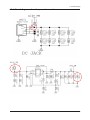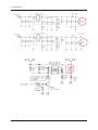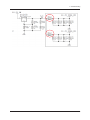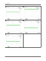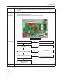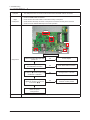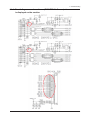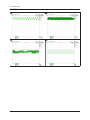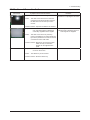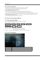
1
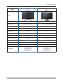
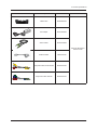
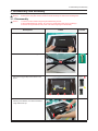
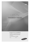
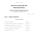
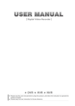
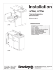
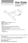
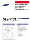
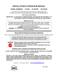
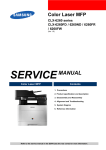
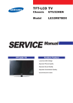
LCD-Monitor Chassis :LS24F9DSM Model :FX2490HD SERVICE TFT-LCD Monitor Manual Contents 1. Precautions 2. Product specifications 3. Disassembly and Reassemble 4. Troubleshooting 5. Exploded View & Part List 6. Wiring Diagram FX2490HD Refer to the service manual in the GSPN (see the rear cover) for the more information. Contents 1. Precautions 1-1. Safety Precautions.......................................................................................................... 1-1 1-2. Servicing Precautions...................................................................................................... 1-2 1-3. Static Electricity Precautions........................................................................................... 1-2 1-4. Installation Precautions................................................................................................... 1-3 2. Product specifications 2-1. Feature & Specifications.................................................................................................. 2-1 2-2. Spec Comparison to the Old Models............................................................................... 2-3 2-3. Accessories..................................................................................................................... 2-4 3. Disassembly and Assembly 3-1. Disassembly.................................................................................................................... 3-1 4. Troubleshooting 4-1. First Checklist for Troubleshooting.................................................................................. 4-1 4-2. No Power......................................................................................................................... 4-2 4-3. PC (ANALOG) No Screen ............................................................................................. 4-7 4-4. DVI/HDMI No Screen.................................................................................................... 4-10 4-5. Faults and Corrective Actions........................................................................................ 4-13 4-6. Adjustment..................................................................................................................... 4-14 4-7. How to Access Service Mode........................................................................................ 4-14 4-8. White Balance - Calibration........................................................................................... 4-16 4-9. White Ratio (Balance) Adjustment................................................................................. 4-17 4-10. Servicing Information................................................................................................... 4-18 4-11. Software Upgrade........................................................................................................ 4-19 4-12. Micom Program Upgrade........................................................................................... 4-20 5. Exploded View & Part List 5-1. Exploded View................................................................................................................. 5-1 5-2. Parts List.......................................................................................................................... 5-2 6. Wiring Diagram 6-1. Wiring Diagram................................................................................................................ 6-1 6-2. Board Connection - Main Board...................................................................................... 6-2 6-3. Connector Functions....................................................................................................... 6-3 6-4. Cables............................................................................................................................. 6-3 GSPN (Global Service Partner Network) Area Web Site North America http://service.samsungportal.com Latin America http://latin.samsungportal.com CIS http://cis.samsungportal.com Europe http://europe.samsungportal.com China http://china.samsungportal.com Asia http://asia.samsungportal.com Mideast & Africa http://mea.samsungportal.com This Service Manual is a property of Samsung Electronics Co.,Ltd. Any unauthorized use of Manual can be punished under applicable International and/or domestic law. © 2010 Samsung Electronics Co.,Ltd. All rights reserved. Printed in Korea P/N: BN82-01109A-00 1. Precautions 1. Precautions 1-1. Safety Precautions Follow these safety, servicing and ESD precautions to prevent damage and to protect against potential hazards such as electrical shock. 1-1-1. Warnings 1. For continued safety, do not attempt to modify the circuit board. 2. Disconnect the AC power and DC power jack before servicing. 1-1-2. Servicing the LCD Monitor 1. When servicing the LCD Monitor, Disconnect the AC line cord from the AC outlet. 2. It is essential that service technicians have an accurate voltage meter available at all times. Check the calibration of this meter periodically. 1-1-3. Fire and Shock Hazard Before returning the monitor to the user, perform the following safety checks: 1. Inspect each lead dress to make certain that the leads are not pinched or that hardware is not lodged between the chassis and other metal parts in the monitor. 2. Inspect all protective devices such as nonmetallic control knobs, insulating materials, cabinet backs, adjustment and compartment covers or shields, isolation resistorcapacitor networks, mechanical insulators, etc. 3. Leakage Current Hot Check (Figure 1-1): WARNING : Do not use an isolation transformer during this test. Use a leakage current tester or a metering system that complies with American National Standards Institute (ANSI C101.1, Leakage Current for Appliances), and Underwriters Laboratories (UL Publication UL1410, 59.7). (READING SHOULD) NOT BE ABOVE 0.5mA LEAKAGE CURRENT TESTER DEVICE UNDER TEST TEST ALL EXPOSED METAL SURFACES 2-WIRE CORD *ALSO TEST WITH PLUG REVERSED (USING AC ADAPTER PLUG AS REQUIRED) EARTH GROUND Figure 1-1. Leakage Current Test Circuit 4. With the unit completely reassembled, plug the AC line cord directly into a 120V AC outlet. With the unit’s AC switch first in the ON position and then OFF, measure the current between a known earth ground (metal water pipe, conduit, etc.) and all exposed metal parts, including: metal cabinets, screwheads and control shafts. The current measured should not exceed 0.5 milliamp. Reverse the power-plug prongs in the AC outlet and repeat the test. 1-1-4. Product Safety Notices Some electrical and mechanical parts have special safetyrelated characteristics which are often not evident from visual inspection. The protection they give may not be obtained by replacing them with components rated for higher voltage, wattage, etc. Parts that have special safety characteristics are identified by on schematics and parts lists. A substitute replacement that does not have the same safety characteristics as the recommended replacement part might create shock, fire and/or other hazards. Product safety is under review continuously and new instructions are issued whenever appropriate. 1-1 1. Precautions 1-2. Servicing Precautions WARNING: An electrolytic capacitor installed with the wrong polarity might explode. Caution: Before servicing units covered by this service manual, read and follow the Safety Precautions section of this manual. Note: If unforeseen circumstances create conflict between the following servicing precautions and any of the safety precautions, always follow the safety precautions. 1-2-1 General Servicing Precautions 1. Always unplug the unit’s AC power cord from the AC power source and disconnect the DC Power Jack before attempting to: (a) remove or reinstall any component or assembly, (b) disconnect PCB plugs or connectors, (c) connect a test component in parallel with an electrolytic capacitor. 2. Some components are raised above the printed circuit board for safety. An insulation tube or tape is sometimes used. The internal wiring is sometimes clamped to prevent contact with thermally hot components. Reinstall all such elements to their original position. 3. After servicing, always check that the screws, components and wiring have been correctly reinstalled. Make sure that the area around the serviced part has not been damaged. 4. Check the insulation between the blades of the AC plug and accessible conductive parts (examples: metal panels, input terminals and earphone jacks). 5. Insulation Checking Procedure: Disconnect the power cord from the AC source and turn the power switch ON. Connect an insulation resistance meter (500 V) to theblades of the AC plug. The insulation resistance between each blade of the AC plug and accessible conductive parts (see above) should be greater than 1 megohm. 6. Always connect a test instrument’s ground lead to the instrument chassis ground before connecting the positive lead; always remove the instrument’s ground lead last. 1-3. Static Electricity Precautions Some semiconductor (solid state) devices can be easily damaged by static electricity. Such components are commonly called Electrostatically Sensitive Devices (ESD). Examples of typical ESD are integrated circuits and some field-effect transistors. The following techniques will reduce the incidence of component damage caused by static electricity. 1. Immediately before handling any semiconductor components or assemblies, drain the electrostatic charge from your body by touching a known earth ground. Alternatively, wear a discharging wrist-strap device. To avoid a shock hazard, be sure to remove the wrist strap before applying power to the monitor. 2. After removing an ESD-equipped assembly, place it on a conductive surface such as aluminum foil to prevent accumulation of an electrostatic charge. 3. Do not use freon-propelled chemicals. These can generate electrical charges sufficient to damage ESDs. 4. Use only a grounded-tip soldering iron to solder or desolder ESDs. 5. Use only an anti-static solder removal device. Some solder removal devices not classified as “anti-static” can generate electrical charges sufficient to damage ESDs. 6. Do not remove a replacement ESD from its protective package until you are ready to install it. Most replacement ESDs are packaged with leads that are electrically shorted together by conductive foam, aluminum foil or other conductive materials. 7. Immediately before removing the protective material from the leads of a replacement ESD, touch the protective material to the chassis or circuit assembly into which the device will be installed. Caution: Be sure no power is applied to the chassis or circuit and observe all other safety precautions. 8. Minimize body motions when handling unpackaged replacement ESDs. Motions such as brushing clothes together, or lifting your foot from a carpeted floor can generate enough static electricity to damage an ESD. 1-2 1. Precautions 1-4. Installation Precautions 1. For safety reasons, more than two people are required for carrying the product. 2. Keep the power cord away from any heat emitting devices, as a melted covering may cause fire or electric shock. 3. Do not place the product in areas with poor ventilation such as a bookshelf or closet. The increased internal temperature may cause fire. 4. Bend the external antenna cable when connecting it to the product. This is a measure to protect it from being exposed to moisture. Otherwise, it may cause a fire or electric shock. 5. Make sure to turn the power off and unplug the power cord from the outlet before repositioning the product. Also check the antenna cable or the external connectors if they are fully unplugged. Damage to the cord may cause fire or electric shock. 6. Keep the antenna far away from any high-voltage cables and install it firmly. Contact with the highvoltage cable or the antenna falling over may cause fire or electric shock. 7. When installing the product, leave enough space (10cm) between the product and the wall for ventilation purposes. A rise in temperature within the product may cause fire. 1-3 1. Precautions Memo 1-4 2. Product specifications 2. Product specifications 2-1. Feature & Specifications Feature ሪሪ Supreme Digital Interface & Networking - With a built-in ATV tuner, it supports TV with no particular set-top box and provides simple access with a single remote control. ሪሪ Excellent Picture Quality ሪሪ Dynamic Contrast - Automatically detects the input visual signal and adjusts to create optimum contrast. ሪሪ ATV Tuner, HDMI, Stereo, SRS Trusurround HD support ሪሪ Convenience -The TV utilizes the HDMI system to implement perfect digital sound and picture quality. 2-1 2. Product specifications Specifications Item LCD Panel Description TFT-LCD Panel, RGB Vertical stripe, normally White, 24.0-inch viewable, 0.27675(H) X 0.27675(V) mm Pixel Pitch Scanning Frequency Horizontal : 30 kHz ~ 81 kHz (Automatic) Vertical: 56 Hz ~ 75 Hz (Automatic) Display Colors 16.7 Million colors Maximum resolution Horizontal: 1920 pixels Vertical: 1080 pixels Input Signal Analog 0.7 Vp-p ±5% positive at 75Ω, internally terminated Input Sync Signal Type : Seperate H/V Level : TTL level Maximum Pixel Clock rate 148.5 MHz Active Display (Horizontal/Vertical) 476.64(H) X 268.11(V) AC power voltage & Frequency AC 110 ~ 240V, 50 ~ 60 Hz Power Consumption 35W <0.3W Dimensions Set (W x D x H) 579.0 x 436.0 x 216.0 mm (with Stand) Weight Set (After installation Stand) 5.3 Kg (with Stand) TV System Tuning: Frequency Synthesize, 579.0 x 363.0 x 36.5 mm (without Stand) 7.5 Kg (Package) System: NT4.43 , PAL , SECAM , DVB-T/C Sound: BG,DK,I,L,L’ Environmental Considerations Operating Temperature: 50˚C ~ 104˚F(10˚C ~ 40˚C) Operating Humidity : 10% ~ 80% Storage Temperature: -4˚C ~ 113˚C(-20˚C ~ 45˚C) Storage Humidity: 5% ~ 95% Antenna Input 75Ω Sound Characteristic - MAX Internal speaker Out : Right: 5W/ Left: 5W - BASS Control Range : -8 dB ~ + 8dB - TREBLE Control Range : -8 dB ~ +8 dB - Headphone Out : 10 mW MAX - Output Frequency : RF : 80 Hz ~ 15 kHz - A/V : 80 Hz ~ 20 kHz 2-2 2. Product specifications 2-2. Spec Comparison to the Old Models 90-MFM FX2490HD 30-MFM B2430HD Screen Size 24” 24” Resolution 1920X1080(FHD) 60Hz 1920X1080(FHD) 60Hz Brightness 250cd/m2 300cd/m2 Contrast Ratio 1000:1 1000:1 Response Time 5ms 5ms Viewing Angle Left/Right/Up/Down : 80˚/80˚/80˚/80˚ Left/Right/Up/Down : 80˚/80˚/80˚/80˚ D-SUB, DVI(HDMI) D-SUB, DVI(HDMI) 35W<0.3W 39W<0.3W Less than 0.3W Less than 2W 5W x 2 3W x 2 MEGA DCR:1 70000:1 Dolby Digital Plus Dolby Digital Pulse DTS SRS Theater sound Dolby Digital Plus Dolby Digital Pulse DTS SRS Theater sound Model Design PC Input Power Consumption DPMS Sound Output Dynamic Contrast Ratio Sound Effect 2-3 2. Product specifications 2-3. Accessories Product Description Code. No Remote Control & Batteries (AAA x 2) BN59-01012A & 4301-000121 Power Cord 3903-000525 Stand Base BN96-15180B D-Sub Cable BN39-00244H Remark Samsung Electronics Service center 2-4 User Manual BN59-01118A Quick Setup Guide BN68-00226R Warranty Card (Not available in all locations) BN68-03169A Cleaning Cloth BN63-01798B 2. Product specifications Product Description Code. No Holder-Wire BN96-06529A DC-Adapter BN44-00399A Stereo Cable Remark BN39-01286A Samsung Electronics Service center SCART Gender BN39-01154F Composite Video,Audio Gender BN39-01154H Component Video Gender BN39-01154C 2-5 2. Product specifications Memo 2-6 5. Exploded View & Part List 5. Exploded View & Part List 5-1. LS24F9DSM/EN - Exploded View M0014 F001A PANEL CB07A RS01A P002A R001A SB01A SB04A 5-1-1. Parts List Location No. Code No. Description & Specification Q’ty SA/SNA CB07A BN96-15179A ASSY BRACKET P-PCB;90-MFM,SECC,T0.8 1 SNA F001A BN96-15176E ASSY COVER P-FRONT;90-MFM,EUROPE,PC+PC V 1 SA M0014 BN94-03900C ASSY PCB MAIN;LS24F9DSM/EN 1 SA P002A BN44-00396A AC VSS-LED DRIVER;90Series 24"(LED drive 1 SA PANEL BN07-00794A LCD-PANEL;M240HW01 V6,AU24016,6bit Hi-FR 1 SA R001A BN96-15182A ASSY COVER P-REAR;90-MFM,EUROPE,PC+ABS,V 1 SA RS01A BN96-15178A ASSY COVER P-REAR SUB;90-MFM,USA,PC+ABS, 1 SA SB01A BN96-15861B ASSY STAND P-BODY;90-MFM,PC+ABS,V0,BR002 1 SA SB04A BN96-15180B ASSY STAND P-BASE;90-MFM,EUROPE,PC+ABS,V 1 SA BN96-15862A ASSY BRACKET P-AV;90-MFM,PCM 0.35,BLK 1 SNA Remark 5-1 5. Exploded View & Part List 5-2. LS24F9DSM/EN - Parts List Service Bom (SA: SERVICE AVAILABLE, SNA: SERVICE NOT AVAILABLE) Level Location No. 0.1 Code No. Description & Specification Q’ty SA/SNA AA01-00004A FOIL;2000,2000,NTR,SEH 1 SNA 0.1 T0603 AA69-00926C PALLET;,WOOD,1100MM,1300MM,120MM,7KG,TIN 1 SNA 0.1 T0077 BH68-00329D LABEL BAR CODE-02;NO CE,NO WT`Y,MPRII,LA 1 SNA 0.1 T0527 BH68-40364A LABEL-SUMMARY;G52,G72,ART,100G,WHT,BLK,W 1 SNA 0.1 PANEL BN07-00794A LCD-PANEL;M240HW01 V6,AU24016,6bit Hi-FR 1 SA 0.1 EC29 BN39-00244H CBF SIGNAL-D-SUB TO D-SUB;D-sub cable,15 1 SA 0.1 P002A BN44-00396A AC VSS-LED DRIVER;90Series 24"(LED drive 1 SA 0.1 P001A BN44-00399A DC VSS(A);AD-6314C,90SERIES MFM,110/230V 1 SA 0.1 T0527 BN68-00129A LABEL SHIPPING-00;LABEL SHIPPING,ART-PAP 1 SNA 0.1 CCM1 BN68-01570A LABEL RATING;ALL,SS,PE,T0.05,90,45,Dark 1 SNA 0.1 BN69-02114A PAD PACKING-EDGE;CB,B800,W200,L2200,YEL, 1 SNA 0.1 BN69-03934A WRAP STRETCH FILM;All,HDPE,0.012,500,300 1 SNA 0.1 BN81-02321A BAG-AIR;LIGHT FLEX PLASTIK,PE WHITE,L120 1 SNA BN94-03900C ASSY PCB MAIN;LS24F9DSM/EN 1 SA ..2 0202-001557 SOLDER-CREAM;LST57-A,D38-63,42SN/57BI/1A 3 SNA ..2 0202-001608 SOLDER-WIRE FLUX;LFC7-107,D0.8,99.3Sn/0. 0.25 SNA 0.1 M0014 ..2 3701-001698 CONNECTOR-DSUB;15P,3ROW,FEMALE,ANGLE,NI 1 SA HB01A 3711-000058 HEADER-BOARD TO CABLE;BOX,4P,1R,2.5MM,AN 1 SA ..2 CN906 3711-004105 CONNECTOR-HEADER;BOX,8P,1R,2.5mm,ANGLE,S 1 SA ..2 DRVCN1 3711-004379 HEADER-BOARD TO CABLE;BOX,4P,1R,2mm,STRA 1 SA 3722-003128 JACK-DC POWER;4P,6.7PI,SN,BLK 1 SNA ET01 BN40-00196A TUNER;DTOS40FVH082A,DTOS40FVH082A,DVB-T/ 1 SA BN97-04732C ASSY SMD;LS24F9DSM/EN,BN94-03900C 1 SNA 0202-001477 SOLDER-CREAM;LST309-M,D20~45um,96.5Sn/3A 4.854 SNA 0401-001056 DIODE-SWITCHING;MMBD4148SE,100V,200mA,SO 12 SA ...3 0403-001180 DIODE-ZENER;BZX84C6V2,5.8-6.6V,350mW,SOT 1 SA ...3 0403-001783 DIODE-ZENER;BZB84-C6V2,5.8/6.6V,300mW,SO 16 SNA ..2 ..2 ..2 ..2 ...3 ...3 DS01A ...3 D0254 0404-001404 DIODE-SCHOTTKY;BAT721C,40V,200mA,SOT-23, 1 SA ...3 T0139 0406-001200 DIODE-TVS;RCLAMP0504F,6/-/-V,150W,SC-70 1 SA ...3 T0139 0406-001271 DIODE-TVS;RCLAMP0524P,6/-/-V,150W,SLP251 4 SNA ...3 SD3 0407-000114 DIODE-SWITCHING;KDS184,80V,100mA,SOT-23, 2 SNA ...3 KQ1 0501-000279 TR-SMALL SIGNAL;KSA1182-Y,PNP,150mW,SOT- 1 SA ...3 Q101 0501-000445 TR-SMALL SIGNAL;KTC3875S-Y,NPN,150mW,SOT 9 SA ...3 PQ02 0501-002080 TR-SMALL SIGNAL;2SC2412K,NPN,200mW,SC-59 2 SA ...3 CEQ2 0505-000110 FET-SILICON;2N7002,N,60V,115mA,7.5ohm,0. 2 SA 0505-001844 FET-SILICON;SI4435DDY-T1-GE3,P,-30V,-11. 3 SA ...3 ...3 M0215 0801-002198 IC-CMOS LOGIC;74LVC14,INVERTER,SOP,14P,1 1 SA ...3 IC104 0801-002630 IC-CMOS LOGIC;74AHCT1G08,2-INPUT AND GAT 1 SA ...3 IC104 0801-003330 IC-CMOS LOGIC;Octal buffer,DQFN,20P,4.5x 2 SA ...3 IC104 0802-001012 IC-CMOS LOGIC;74LCX245,TRANSCEIVER,DQFN, 1 SNA ...3 1006-001266 IC-LINE TRANSCEIVER;3232,TSSOP,16P,174MI 1 SA ...3 1006-001474 IC-LINE DRIVER;DRV604PWP,HPSSOP,28P,9.8x 1 SA ...3 IC112 1103-000129 IC-EEPROM;24C02,2Kbit,256x8,SOP,8P,5x4mm 2 SA ...3 IC112 1103-001310 IC-EEPROM;24LC02B,256X8BIT,SOIC,8P,3.91X 2 SA 1103-001487 IC-EEPROM;AT24C256C-SSHL-T,256Kbit,32Kx8 1 SA ...3 ...3 1105-002153 IC-DDR2 SDRAM;K4T1G164QF-BCF8,DDR2,1Gbit 2 SNA ...3 1201-002994 IC-POWER AMP;NTP-7300S,QFN,56P,8x8mm,DUA 1 SA 5-2 Remark 5. Exploded View & Part List Level Location No. Code No. Description & Specification Q’ty SA/SNA ...3 T0087 1203-001815 IC-POSI.FIXED REG.;78M09,TO-252,3P,PLAST 1 SA ...3 T0087 1203-002835 IC-POSI.FIXED REG.;KIA7805AF,DPAK,3P,6.6 1 SA ...3 T0087 1203-002898 IC-POSI.FIXED REG.;G950T45R,T0-252,3P,6. 1 SA ...3 1203-004364 IC-VOL. DETECTOR;RT9818C-42PV,SOT-23,3P, 1 SA ...3 1203-006013 IC-DC/DC CONVERTER;AOZ1031AI,SO-8,8P,4.9 3 SA 1203-006017 IC-VOL. DETECTOR;RT9824GJ8,TSOT23,8P,2.9 1 SA 1203-006138 IC-POSI.ADJUST REG.;AP1117DGZ-13-89,TO-2 1 SA ...3 1203-006142 IC-DC/DC CONVERTER;BD8924G,5P,2.9x1.6x1. 1 SA ...3 1203-006337 IC-POSI.FIXED REG.;G9091-330T11U,SOT-23- 1 SA ...3 1204-003197 IC-DECODER;SEMS18-LF,LFBGA,568P,20x20mm, 1 SA ...3 1205-003201 IC-BUS SWITCH;TC7WB125FK,SSOP,8P,2x2.3mm 1 SA ...3 1205-003479 IC-SWITCH;TPS2051BDBVR,SOT-23,5P,2.9x1.6 1 SA ...3 1205-003735 IC-SWITCH;AP2151WG-7,SOT25,5P,2.9x1.6mm, 1 SA ...3 1405-001271 VARISTOR;20Vdc,5A,1.0x0.5x0.6mm,TP 25 SA ...3 ...3 IC012 ...3 PR4 2007-000052 R-CHIP;10Kohm,1%,1/10W,TP,1608 1 SA ...3 ND51C2 2007-000066 R-CHIP;20Kohm,1%,1/10W,TP,1608 1 SNA ...3 PR6 2007-000072 R-CHIP;47ohm,5%,1/10W,TP,1608 4 SNA ...3 AR158 2007-000077 R-CHIP;470ohm,5%,1/10W,TP,1608 2 SA ...3 AR150 2007-000078 R-CHIP;1Kohm,5%,1/10W,TP,1608 1 SA ...3 FMR4 2007-000080 R-CHIP;2Kohm,5%,1/10W,TP,1608 1 SNA ...3 MROP1 2007-000090 R-CHIP;10Kohm,5%,1/10W,TP,1608 1 SA ...3 KAR9 2007-000093 R-CHIP;20Kohm,5%,1/10W,TP,1608 1 SA ...3 MR604 2007-000137 R-CHIP;2Kohm,5%,1/16W,TP,1005 2 SNA ...3 R105 2007-000138 R-CHIP;100ohm,5%,1/16W,TP,1005 24 SA ...3 AR49 2007-000140 R-CHIP;1Kohm,5%,1/16W,TP,1005 13 SNA ...3 MR306 2007-000141 R-CHIP;2.2Kohm,5%,1/16W,TP,1005 6 SNA ...3 AVR73 2007-000142 R-CHIP;2.7Kohm,5%,1/16W,TP,1005 1 SA ...3 R319 2007-000143 R-CHIP;4.7Kohm,5%,1/16W,TP,1005 57 SNA ...3 R104 2007-000148 R-CHIP;10Kohm,5%,1/16W,TP,1005 52 SA ...3 MR36 2007-000153 R-CHIP;22Kohm,5%,1/16W,TP,1005 7 SNA ...3 AR43 2007-000155 R-CHIP;27Kohm,5%,1/16W,TP,1005 2 SNA ...3 MR13 2007-000157 R-CHIP;47Kohm,5%,1/16W,TP,1005 7 SNA ...3 DR39 2007-000162 R-CHIP;100Kohm,5%,1/16W,TP,1005 6 SNA ...3 2007-000165 R-CHIP;200Kohm,5%,1/16W,TP,1005 1 SNA ...3 R509 2007-000170 R-CHIP;1Mohm,5%,1/16W,TP,1005 1 SNA ...3 R111 2007-000171 R-CHIP;0ohm,5%,1/16W,TP,1005 10 SNA ...3 HDR17 2007-000172 R-CHIP;10ohm,5%,1/16W,TP,1005 2 SNA ...3 R338 2007-000173 R-CHIP;22ohm,5%,1/16W,TP,1005 22 SNA ...3 UR23 2007-000174 R-CHIP;47ohm,5%,1/16W,TP,1005 2 SNA ...3 PFRF2 2007-000219 R-CHIP;1.2Kohm,1%,1/10W,TP,1608 1 SNA ...3 ER13 2007-000669 R-CHIP;2Kohm,1%,1/10W,TP,1608 2 SNA ...3 R299 2007-000772 R-CHIP;33Kohm,1%,1/10W,TP,1608 2 SA ...3 R124 2007-000775 R-CHIP;33Kohm,5%,1/16W,TP,1005 2 SNA ...3 HR10 2007-000962 R-CHIP;5.1Kohm,1%,1/10W,TP,1608 1 SA ...3 R858 2007-001007 R-CHIP;51Kohm,1%,1/10W,TP,1608 1 SA 2007-001285 R-CHIP;5.6ohm,5%,1/16W,TP,1005 2 SA 36 SNA ...3 ...3 OTR1 2007-001292 R-CHIP;33ohm,5%,1/16W,TP,1005 ...3 DR43 2007-001298 R-CHIP;51ohm,5%,1/16W,TP,1005 2 SNA ...3 DR1 2007-001301 R-CHIP;68ohm,5%,1/16W,TP,1005 10 SA ...3 R326 2007-001325 R-CHIP;3.3Kohm,5%,1/16W,TP,1005 2 SNA Remark 5-3 5. Exploded View & Part List Level Location No. ...3 Code No. Description & Specification Q’ty SA/SNA 2007-001333 R-CHIP;18Kohm,5%,1/16W,TP,1005 6 SNA ...3 PR24 2007-002970 R-CHIP;56ohm,5%,1/16W,TP,1005 17 SA ...3 HDR8 2007-007095 R-CHIP;390ohm,5%,1/16W,TP,1005 1 SA ...3 DR4 2007-007142 R-CHIP;10Kohm,1%,1/16W,TP,1005 3 SNA ...3 2007-007156 R-CHIP;1ohm,5%,1/16W,TP,1005 5 SNA ...3 2007-007318 R-CHIP;1Kohm,1%,1/16W,TP,1005 4 SNA ...3 2007-007334 R-CHIP;200Kohm,1%,1/16W,TP,1005 2 SNA ...3 DR157 2007-007650 R-CHIP;274ohm,1%,1/10W,TP,1608 1 SA ...3 R8 2007-007721 R-CHIP;560ohm,1%,1/10W,TP,1608 1 SA 2007-007861 R-CHIP;62Kohm,1%,1/16W,TP,1005 2 SA 2007-008015 R-CHIP;75ohm,1%,1/16W,TP,1005 14 SA 2007-008275 R-CHIP;30Kohm,1%,1/16W,TP,1005 1 SNA ...3 ...3 MR11 ...3 ...3 ZRN10 2011-001261 R-NETWORK;33ohm,5%,1/16W,L,CHIP,8P,TP,2. 2 SA ...3 DAR09 2011-001262 R-NETWORK;22ohm,5%,1/16W,L,CHIP,8P,TP,2. 12 SA 2011-001264 R-NETWORK;10ohm,5%,1/16W,L,CHIP,8P,TP,2. 6 SNA 2011-001344 R-NETWORK;100ohm,5%,1/16W,L,CHIP,8P,TP,2 2 SA ...3 2011-001402 R-NETWORK;56ohm,5%,1/16W,L,CHIP,8P,TP,2. 8 SA ...3 2011-001427 R-NETWORK;0ohm,5%,1/16W,L,CHIP,8P,TP,2.0 6 SNA ...3 2011-001449 R-NETWORK;22ohm,5%,1/16W,L,4P,TP,1010 5 SA ...3 2011-001587 R-NETWORK;100ohm,5%,1/16W,L,CHIP-V,4P,TP 2 SNA PC43 2203-000233 C-CER,CHIP;0.1nF,5%,50V,C0G,TP,1005 4 SA ...3 C134 2203-000257 C-CER,CHIP;10nF,10%,50V,X7R,TP,1608 1 SA ...3 MC302 2203-000425 C-CER,CHIP;.018nF,5%,50V,C0G,TP,1005 4 SA ...3 C254 2203-000438 C-CER,CHIP;1nF,10%,50V,X7R,TP,1005 15 SA ...3 C507 2203-000489 C-CER,CHIP;2.2nF,10%,50V,X7R,TP,1005 4 SA ...3 FC04 2203-000552 C-CER,CHIP;0.02nF,5%,50V,C0G,1608 2 SNA ...3 V1233 2203-000575 C-CER,CHIP;220nF,10%,25V,X7R,TP,2012 6 SNA ...3 AD480 2203-000679 C-CER,CHIP;0.027nF,5%,50V,C0G,1005 3 SNA ...3 DC25 2203-000812 C-CER,CHIP;.033nF,5%,50V,C0G,TP,1005 2 SA ...3 CK40B 2203-000838 C-CER,CHIP;0.39NF,5%,50V,C0G,TP,1608 2 SNA ...3 HDC5 2203-001072 C-CER,CHIP;0.056nF,5%,50V,NP0,1005 4 SA ...3 C3A09 2203-001103 C-CER,CHIP;6.8nF,10%,50V,X7R,TP,1608 1 SA ...3 AD480 2203-001428 C-CER,CHIP;470nF,10%,50V,X7R,TP,2012 4 SNA ...3 C3303 2203-002041 C-CER,CHIP;0.47nF,10%,50V,X7R,1608 1 SA ...3 AD480 2203-002285 C-CER,CHIP;10nF,10%,50V,X7R,1005 13 SNA ...3 AD480 2203-002525 C-CER,CHIP;0.56nF,10%,50V,X7R,TP,1005 6 SNA ...3 C33 2203-002687 C-CER,CHIP;1.2nF,10%,50V,X7R,TP,1005 4 SA ...3 AAC1 2203-005249 C-CER,CHIP;100nF,10%,50V,X7R,TP,1608 10 SNA ...3 TE3 2203-005261 C-CER,CHIP;1000nF,10%,25V,X7R,TP,3216 1 SNA ...3 AD480 2203-005344 C-CER,CHIP;22nF,10%,25V,X7R,TP,1005,- 1 SNA ...3 AD480 2203-005393 C-CER,CHIP;.005nF,0.1pF,50V,NP0,TP,1005 1 SNA ...3 AD480 2203-005809 C-CER,CHIP;1000nF,10%,16V,X7R,TP,2012 1 SC ...3 AD480 2203-006126 C-CER,CHIP;47nF,10%,16V,X7R,TP,1005 24 SNA ...3 PC11 2203-006141 C-CER,CHIP;1000nF,10%,16V,X5R,1608 3 SNA ...3 C102 2203-006158 C-CER,CHIP;100nF,10%,16V,X7R,TP,1005 81 SNA ...3 JC10 2203-006324 C-CER,CHIP;2200nF,10%,10V,X5R,1608 7 SA ...3 AD480 2203-006336 C-CER,CHIP;10000nF,10%,25V,X5R,3216 30 SA ...3 C125 2203-006361 C-CER,CHIP;10000nF,10%,10V,X5R,TP,2012 39 SC ...3 HE4 2203-006474 C-CER,CHIP;22000nF,20%,6.3V,X5R,2012 8 SA ...3 HDC11 2203-006562 C-CER,CHIP;1000nF,10%,10V,X5R,TP,1005 14 SNA ...3 ...3 ...3 5-4 HRP2 Remark 5. Exploded View & Part List Level Location No. Code No. Description & Specification Q’ty SA/SNA ...3 AD480 ...3 AD480 2203-006824 C-CER,CHIP;4700nF,10%,10V,X5R,1608 1 SNA 2203-006841 C-CER,CHIP;1000nF,10%,16V,X5R,TP,1005 1 SNA ...3 ...3 AD480 2203-007513 C-CER,CHIP;10000nF,10%,10V,X5R,TP,1608 1 SA T0052 2703-000158 INDUCTOR-SMD;1uH,10%,2012 2 SA ...3 T0052 2703-000296 INDUCTOR-SMD;680nH,10%,1608 1 SA ...3 VL6 2703-000398 INDUCTOR-SMD;10uH,10%,3225 2 SA ...3 T0052 2703-001239 INDUCTOR-SMD;3.3uH,10%,1608 3 SA ...3 T0052 2703-002801 INDUCTOR-SMD;3.9uH,20%,7070 1 SA ...3 T0052 2703-003150 INDUCTOR-SMD;4.7uH,20%,5050 4 SNA ...3 T0052 2703-003559 INDUCTOR-SMD;4.7uH,20%,8080 3 SNA ...3 2703-003890 INDUCTOR-SMD;47uH,10%,3225 1 SA ...3 X202 2801-003326 CRYSTAL-SMD;24MHz,30ppm,28-ABX,20pF,50oh 1 SA ...3 X202 2801-003773 CRYSTAL-SMD;12MHz,30ppm,28-AAN,20pF,50oh 1 SA ...3 F103 2901-001506 FILTER-EMI SMD;5V,0.13A,0pF,2x1x0.5mm,TP 4 SA ...3 T0568 3301-001236 BEAD-SMD;60ohm,1608 5 SA ...3 T0568 3301-001404 BEAD-SMD;30ohm,2012,TP,15.9OHM/30MHz 2 SA ...3 T0568 3301-002039 BEAD-SMD;26ohm,1608,TP 38 SA ...3 T0313 3404-001207 SWITCH-TACT;12V,50mA,160gf,6.2X6.2,SPST 1 SA 3701-001293 CONNECTOR-HDMI;19P,2R,FEMALE,SMD-A,AU 2 SA ...3 ...3 CN906 3707-001095 CONNECTOR-OPTICAL;SMD-A(Ultra Slim),SPDI 1 SA ...3 AC510 3708-001150 CONNECTOR-FPC/FFC/PIC;30P,1mm,SMD-A,SN,Y 1 SA 3710-002276 SOCKET-INTERFACE;24P,1R,0.5mm,SMD-A,AU,B 1 SA 3711-005471 HEADER-BOARD TO CABLE;BOX,12P,1R,1.25mm, 1 SA ...3 3722-003044 JACK-USB;4P/1C,NI,BLK,SMD-A,A-TYPE 1 SA ...3 BN41-01531A PCB MAIN;90-MFM,FR-4,4,1.2T,212x158 1 SNA ...3 BN97-04878A ASSY MICOM;90-MFM,2010.06.08,T-MSXMDEUC, 1 SNA ...3 ...3 HB01A ....4 1107-001940 IC-NAND FLASH;KFG1G16U2D-HIB6,1Gbit,64Mx 1 SNA ...3 BN97-04879A ASSY MICOM;90-MFM,2010.06.08,T-MSXMDEUS- 1 SNA ....4 IC520 0903-001651 IC-MICROCONTROLLER;61P802-RG480WT,LQFP,4 1 SNA ...3 D0254 0404-001271 DIODE-SCHOTTKY;SSA34,40V,3000mA,SMA,TP 1 SA ...3 AD480 2203-005968 C-CER,CHIP;4.7NF,10%,50V,X7R,TP,1005 2 SNA ..2 T0066 BP62-00017A HEAT SINK-ES;SP-50L2HX,A6063S,T2.0,26.2, 1 SNA ..2 3709-001641 CONNECTOR-CARD SLOT;68P(U/SLIM 60mm) W/L 1 SNA ..2 3722-003156 JACK-PHONE;1/7P,NI,LAUREL-GREEN,ANGLE 2 SA ..2 3722-003158 JACK-PHONE;1/7P,NI,BLK,ANGLE 2 SA ..2 3722-003159 JACK-PHONE;1/7P,NI,YEL,ANGLE 1 SA BN96-15345F ASSY ACCESSORY;LS24F9DSM/EN 1 SNA 0.1 ACCE1 ..2 T0120 ..2 ..2 4301-000121 BATTERY-MN;1.5V,R03,10.5x44.5m,HOLDER,7. 2 SNA AA68-03576C MANUAL FLYER-LEAFLET;comm,Samsung,Russia 1 SNA AA69-02656A BAG ACCESSORY;PJTV,LDPE,T0,05,L400,W280, 1 SNA ..2 M0019 BH68-70448A CARD-01;TFT LCD,SRC,RUSSIA,S/W,120,W210* 1 SNA ..2 M0114 BN39-01154C CBF SIGNAL;Chelsea Slim, STEREO Plug to 1 SA ..2 M0114 BN39-01154F CBF SIGNAL;UE40B7000WWXXC,24P/20P,30AWG, 1 SA ..2 M0114 BN39-01154H CBF SIGNAL;UE40B7000WWXXC,RCA 3PIN,30AWG 1 SA ..2 EC08 BN39-01286A CBF SIGNAL-STEREO;3p,UL2547, Audio Stand 1 SA BN59-01118A S/W DRIVER-00,IB;FX2490HD,Europe,Samsung 1 SNA M9889 BN63-01798B CLOTH-CLEAN;cloth,180,200,sea blue,ToC 1 SNA ..2 BN68-00226R MANUAL FLYER-03,WARRANTY CARD;comm,Samsu 1 SNA ..2 BN68-01925G MANUAL FLYER-WARRANTY CARD;comm,Samsung, 1 SNA ..2 BN68-02462B LABEL-STICKER;CIS,T0.05,93,40,TV-MONITOR 1 SNA ..2 BN68-03169A MANUAL FLYER-QSG;FX2490HD,Samsung,20Lang 1 SNA ..2 ..2 Remark 5-5 5. Exploded View & Part List Level Location No. Code No. Description & Specification Q’ty ..2 T0010 BN96-06529A ASSY HOLDER P-WIRE;MCKINLEY,ABS HB,BK23 1 SA 6902-000336 BAG ZIPPER;LDPE,T0.05,W70,L80,TRP,0.500g 1 SNA BN61-03555A HOLDER-WIRE;MCKINLEY,ABS HB,BK26 1 SNA BN96-13879F ASSY ACCESSORY-SCREW;FX2490HD,6001-00058 1 SNA ...3 ...3 M0114 ..2 SA/SNA ...3 T0081 6001-000581 SCREW-MACHINE;PH,+,M4,L12,NI PLT,SWRCH18 2 SNA ...3 T0524 6902-001169 BAG PE;LDPE,T0.1,W60,L60,Sealing 1 SNA ..2 EC11 3903-000525 CBF-POWER CORD;DT,CEE,LP-21L,250V,2.5A,B 1 SA ..2 EC29 BN39-00244H CBF SIGNAL-D-SUB TO D-SUB;D-sub cable,15 1 SA ..2 BN68-02186C MANUAL FLYER-TOC GUIDE;ALL,SAMSUNG,36LEN 1 SNA 0.1 BN96-15776A ASSY MISC P-SKD;LS24F9DSM/EN,JASZ 1 SNA SNA ..2 M0081 6003-000115 SCREW-TAPTYPE;BH,+,B,M3,L6,ZPC(BLK),SWRC 6 ..2 SCREW 6003-001782 SCREW-TAPTYPE;BH,+,B,M4,L12,ZPC(BLK),SWR 4 SA ..2 T0562 6046-001014 STAND OFF;#4-40,L6,NI PLT,C3601 2 SNA ..2 T0524 6902-000520 BAG PE;HDPE/NITRON,T0.015/T0.5(DOUBLE),W 1 SNA BH68-00659J LABEL BOX-00;ALL MODEL,MOJO 90G,90,95,WH 1 SNA ..2 ..2 M2893 BN39-00419E LEAD CONNECTOR;ECOFIT 25inch,UL1571#30,1 1 SA ..2 T0074 BN59-01012A REMOCON;TM950,SAMSUNG,20PIN SINGLE,48KEY 1 SA ..2 HDP01 BN61-06644A HOLDER-PCB;LC750,NYNOL66,V0 1 SNA ..2 BN68-03146A LABEL-MONITOR-POP;90 MFM POP,WW,PET,T0.0 1 SNA ..2 BN69-05228A CUSHION-01,SET;90 Series 24",EPS,M50 1 SNA ..2 BN69-05327A BOX-SET;F2490HD,CB,A-01,SW2,YEL,W640,D53 1 SNA BN96-02895A ASSY MISC P-01,HANDLE PACKING;ALL MODEL, 1 SNA BN66-00007A LEVER-TOP;ALL MODEL,LDPE,WHITE,5.8g 1 SNA ..2 M0245 ...3 ...3 BN66-00008A LEVER-BOTTOM;ALL MODEL,LDPE,WHITE,4.01g 1 SNA ..2 FL06 BN96-12453X ASSY CABLE P-FFC;90-MFM,FFC,JPC-S01703,2 1 SA ..2 RS01A BN96-15178A ASSY COVER P-REAR SUB;90-MFM,USA,PC+ABS, 1 SA ...3 CCM1 BN63-02183D COVER-SHEET;Rhcm,PE Vinyl,T0.05,680mm,20 0.3 SNA ...3 RS01 BN63-07310A COVER-REAR SUB;90 Series 24",ABS+PC,V0,B 1 SNA ..2 CB07A BN96-15179A ASSY BRACKET P-PCB;90-MFM,SECC,T0.8 1 SNA BN61-02428E STUD-PEM;PNA,M4,D8,L10,ZPC(SIL),SUM24L 4 SNA ...3 ...3 CB07 BN61-06725A BRACKET-PCB;90 Series 24",EGI-SECC,T0.8 1 SNA ...3 T0073 AA63-01413H GASKET-EMI;42Q7,Fabric Type,2mm,10mm,78m 2 SNA ...3 M0131 ...3 BH63-00104A GASKET;POSEIDON,CONDUCTIVE FABRIC,2MM,10 2 SNA BN60-00162X SPACER-FOAM;FOAM,30000mm,Dark Gray,1T,15 0.05 SNA SA ..2 R001A BN96-15182A ASSY COVER P-REAR;90-MFM,EUROPE,PC+ABS,V 1 ...3 M0081 6003-000337 SCREW-TAPTYPE;BH,+,S,M4,L10,ZPC(BLK),SWR 1 SA ...3 M0081 6003-001001 SCREW-TAPTYPE;FH,+,B,M3,L8,ZPC(BLK),SWRC 11 SNA ...3 T0069 AA60-00091B SPACER-FELT;FELT,100X10,BLK,T0.35 1 SNA BN61-06726A BRACKET-GUIDE STAND;90 Series 24",HGI,T2 1 SNA ...3 ...3 CCM1 BN63-02183D COVER-SHEET;Rhcm,PE Vinyl,T0.05,680mm,20 0.5 SNA ...3 R001 BN63-07307A COVER-REAR;90 Series 24",ABS+PC,V0,BR002 1 SNA ...3 BN68-02998A LABEL-STICKER;WW,PET,T0.05,55,20,30MFM L 1 SNA ...3 BN68-03075A LABEL-TERMINAL SIDE;90series,PET,T0.05,E 1 SNA ...3 ...3 SB01A ....4 M0081 BN68-03076A LABEL-TERMINAL BOTTOM;90series,PET,T0.05 1 SNA BN96-15861B ASSY STAND P-BODY;90-MFM,PC+ABS,V0,BR002 1 SA 6003-001001 SCREW-TAPTYPE;FH,+,B,M3,L8,ZPC(BLK),SWRC 3 SNA ....4 BN63-07309B COVER-STAND FRONT;90series,ABS+PC,V0,H/G 1 SNA ....4 BN63-07311B COVER-STAND REAR;90series,ABS+PC,V0,BR00 1 SNA ....4 SH03A BN96-15166A ASSY HINGE P;90 Series 24",SM50C,T2.3 1 SNA ..2 FL06 BN96-15355B ASSY CABLE P-FFC;90-MFM,FFC,JPC-S01807,2 1 SA BN73-00206A SILICON/RUBBER-GAPPAD;UE40B7000WWXXC,SIL 1 SNA ..2 5-6 Remark 5. Exploded View & Part List Level Location No. Code No. Description & Specification ..2 SB04A BN96-15180B ASSY STAND P-BASE;90-MFM,EUROPE,PC+ABS,V 1 SA ...3 M0081 6003-001001 SCREW-TAPTYPE;FH,+,B,M3,L8,ZPC(BLK),SWRC 12 SNA 6902-000794 BAG PE;HDPE,T0.015,W300,L550,TRP,28,0,SU 1 SNA SG01 BN61-06736A GUIDE-STAND NECK;90Series 24",PC+GF,BLK, 1 SNA ...3 ...3 Q’ty SA/SNA ...3 BN63-07312B COVER-STAND STAND;90series,ABS+PC,V0,BR0 1 SNA ...3 BN63-07313B COVER-STAND BOTTOM;90series,ABS+PC,VO,BR 1 SNA ...3 BN63-07314B COVER-STAND TOP(FL);90series,ABS HB,V0,P 1 SNA ...3 BN63-07315B COVER-STAND TOP(FR);90series,ABS HB,V0,P 1 SNA ...3 BN63-07316B COVER-STAND TOP(RL);90series,ABS HB,V0,P 1 SNA ...3 BN63-07317B COVER-STAND TOP(RR);90series,ABS HB,V0,P 1 SNA ...3 BN68-02304C LABEL-STICKER;WW,T0.05,50,10,LAVERDER 19 1 SNA ...3 BN68-02482C MANUAL FLYER-STAND;comm,Samsung,W/W,W/P8 1 SNA BN73-00077A RUBBER FOOT;MATISSE,BUMPON,#13.5,T2.0,GR 4 SNA ...3 AR011 BN96-15862A ASSY BRACKET P-AV;90-MFM,PCM 0.35,BLK 1 SNA ...3 ..2 T0073 BH63-00008A GASKET-EMI;IB10LO,CONDUCTIVE FABRIC,3MM, 2 SNA ...3 HDP01 BN61-06644A HOLDER-PCB;LC750,NYNOL66,V0 1 SNA ...3 CB01 BN61-06723A BRACKET-AV;90 Series 24",PCM T0.5 BLK,T0 1 SNA ..2 F001A BN96-15176E ASSY COVER P-FRONT;90-MFM,EUROPE,PC+PC V 1 SA BN60-00162V SPACER-FOAM;FOAM,50000mm,Dark Gray,0.5T, 1.7 SNA ...3 ...3 CCM1 BN63-02183D COVER-SHEET;Rhcm,PE Vinyl,T0.05,680mm,20 0.5 SNA ...3 F001 BN63-07305B COVER-FRONT;90 Series 24",PC+PC,V0,TP001 1 SNA ...3 FW04 BN64-01470A WINDOW-RMC;90 Series 24",PC VIOLET,TP000 1 SNA ...3 T0527 BN68-00798D LABEL-ENERGY,STAR;L/M,W/W,PET,T0.05,9.3, 1 SNA BN68-03130A LABEL-STICKER;WW,ALL,Art Paper,19,8,"LED 1 SNA ...3 SP01A BN96-12945D ASSY SPEAKER P;16ohm,4pin,5W,L650/R250,9 1 SA ...3 FB01A BN96-15735A ASSY BOARD P-FUNCTION;LS24F9DSM/EN,CT500 1 SA HA83-00057B LP-TAPE-CELLULOSE;,HA02-030010,T0,046,W7 1.8 SNA 3903-000525 CBF-POWER CORD;DT,CEE,LP-21L,250V,2.5A,B 1 SA ...3 ..2 0.1 EC11 Remark 5-7 3. Disassembly and Assembly 3. Disassembly and Assembly This section describes the disassembly and reassembly sequences for this monitor. Warning:As this monitor has parts that are sensitive to static electricity, be careful when handling them. 3-1. Disassembly Caution: 1. Turn the monitor off before beginning the disassembly process. 2. When disassembling the monitor, do not use any metal tools except for the provided jig. 3. Remove the signal cable and the power cord before beginning the disassembly. Description Photo Screws 1. Lift up and remove the rear sub cover. 2. Remove the 2 Screws Shown in the figure. 3. Remove the 6(type A/B) screws shown in the figure. Type A Type B 4. Left hand hold a Cover-Front and Push Down following arow direction, the other hand hold a Hinge and then lift up. 3-1 3. Disassembly and Assembly Description Photo Screws 5. Lift up and Remove the Rear cover. 6. Lift up the cable holder and release Function & Speaker cables. LVDS cable 7. Disconnect the LVDS cable. 8. Disassemble the speaker. Speakers Function&Speaker wire LVDS cable Speakers 9. Unlock the Cable connectors and Disconnect the panel lamp Cables. 3-2 3. Disassembly and Assembly Description Photo Screws 10.Disconnect Driver Board harness and Function & speaker Cable. 11.Remove 4 screws and remove the main board and the driver board. 12.Remove the Panel shield. 13.Remove the Panel. ※ Reassembly procedures are in the reverse order of disassembly procedures. 3-3 3. Disassembly and Assembly Memo 3-4 4. Troubleshooting 4. Troubleshooting 4-1. First Checklist for Troubleshooting Self-Test Feature Check Your monitor provides a self test feature that allows you to check whether your monitor is functioning properly. 1. Turn off both your computer and the monitor. 2. Unplug the video cable from the back of the computer 3. Turn on the monitor. If the monitor is functioning properly, you will see a box in the illustration below. . This box appears during normal operation if the video cable becomes disconnected or damaged. 4. Turn off your monitor and reconnect the video cable; then turn on both your computer and the monitor. If your monitor screen remains blank after using the previous procedure, check your video controller and computer system; your monitor is functioning properly. Warning Messages If there is something wrong with the input signal, a message appears on the screen or the screen goes blank although the power indicator LED is still on. The message may indicate that the monitor is out of scan range or that you need to check the signal cable. Environment The location and the position of the monitor may influence the quality and other features of the monitor. If there are any sub woofer speakers near the monitor, unplug and relocate the woofer to another room. Remove all electronic devices such as radios, fans, clocks and telephones that are within 3 feet (one meter) of the monitor. Useful Tips ▶ A monitor recreates visual signals received from the computer. Therefore, if there is trouble with the computer or the video card, this can cause the monitor to become blank, have poor coloring, noise, Video mode not supported, etc. In this case, first check the source of the problem, and then contact the Service Center or your dealer. ▶ Judging the monitor’s working condition If there is no image on the screen or a “Not Optimum Mode”, “Recommended Mode 1920 X 1080 60Hz” message comes up, disconnect the cable from the computer while the monitor is still powered on. - If there is a message coming up on the screen or if the screen goes white, this means the monitor is in working condition. - In this case, check the computer for trouble. 4-1 4. Troubleshooting 4-2. No Power Symptom -- The LED on the front panel of the monitor does not work when the power is connected and the Power button is pressed. -- Check if the Power switch on the rear panel of the monitor has been turned on. Major checkpoints -- Check the SMPS fuse and the IP-Board output power. -- Check the connection between the IP-Board and the Main Board inside the monitor. -- Check the power part of the Main Board and check if a similar symptom appears at another output terminal. IC203 IC1111 IC1021 IC204 IC2001 IC208 CN201 Main Board Front Diagnostics Does proper 14.5V appear at pin No.1 of CN210? 1 No Check DC Power Adapter Yes Does proper 14.5V appear at BD223? 1 Does proper 5V appear at C213, BD1021? 2 No Check related circuit of IC2001, IC1021. No Check related circuit of IC203, IC204. No Check related circuit of IC208. Yes Does proper 3.3V , 1.29V appear at pin C281, C221? 3 4 Yes Does proper 1.9V appear at BD212, BD213? 5 Yes Change main board for Scaler(IC1111) problem Caution 4-2 Make sure Power connection before checking the Main Board. 4. Troubleshooting 4-2-1. Circuit diagrams when the power does not turn on 4-3 4. Troubleshooting 4-4 4. Troubleshooting 4-5 4. Troubleshooting 4-2-2. Waveforms 1 2 3 4 5 4-6 4. Troubleshooting 4-3. PC (ANALOG) No Screen Symptom -- The LED power is on but no picture is displayed on the screen when the D-SUB cable is connected -- Even though the LED power turns on, the screen is blank when connecting the VGA cable. Major checkpoints -- Check the D-sub cable connections. -- Check whether the LVDS cable is connected correctly to the panel. -- Check whether the lamp connector of the panel is connected correctly to the IP board. CN1404 IC1111 CN902 CN201 Main Board Front Diagnostics Does led persists Red light after power on? No Check Power Adapter No Check D-sub cable connection. No Check PC state. No Change main board because of scaler problem. Yes Does proper 5V appear at pin No. 9 of CN902? Yes Does proper V-sync 6 and H-sync 7 appear at BD905 and BD904? Yes Does proper clock signals appear at pin NO.11,12,23,24 of CN1404? 8,9 Yes Check connection between main board and panel. Change Panel. Caution Make sure Power connection before checking the Main Board. 4-7 4. Troubleshooting 4-3-1. Circuit diagrams and waveforms (Analog) when no screen is displayed on the monitor 4-8 4. Troubleshooting 4-3-2. Waveforms 6 7 8 9 4-9 4. Troubleshooting 4-4. DVI/HDMI No Screen Symptom -- The LED power turns on but the screen is blank when the HDMI cable is connected. -- Check the HDMI cable connections. Major checkpoints -- Check whether the LVDS cable is connected correctly to the panel. -- Check whether the lamp connector of the panel is connected correctly to the IP board. -- Check the circuit related HDMI input and scaler operation. CN1404 IC1111 CN1003 CN201 CN1002 Main Board Front Diagnostics Does led persists Red light after power on? No Power adapter No Check HDMI cable connection No Change IC1071 or IC1072. No Change main board because of scaler problem Yes Dose proper 5V appear at pin No. 18 of CN1002 or CN1003? Yes Does proper signals appear at pin No.15(SCL) 0 and No.16(SDA) ! of CN1002 or CN1003? Yes Does proper clock signals appear at pin NO.11,12, 23, 24 of CN1404? @,# Yes Check connection between main board and panel. Change Panel. Caution 4-10 Make sure Power connection before checking the Main Board. 4. Troubleshooting 4-4-1. Circuit diagrams and waveforms (DVI/HDMI No Screen) when no screen is displayed on the monitor 4-11 4. Troubleshooting 4-4-2. Waveforms 0 ! @ # 4-12 4. Troubleshooting 4-5. Faults and Corrective Actions Fault Photo Symptoms and Corrective Actions Symptoms: DVI signals are not recognized. Causes: This fault occurs when the PC does not recognize the mode information because the DVI DDC has not been input to the monitor. Remarks * Refer to the Training Manual for information on inputting the DVI DDC. Corrective Actions: Input the DVI DDC to the monitor. Symptoms:When the monitor is turned on, only a full white pattern is displayed continually regardless of the signals. * A full white pattern is a feature of the TN panel and is displayed when no video signals are supplied. Causes: This fault occurs when only the lamp power is supplied and no video signals are input to the panel due to a fault or incorrect connections of the LVDS cable. Corrective Actions: Replace or reconnect the LVDS cable correctly so that video signals can be supplied to the panel. Symptoms:When connecting the DVD, noise occurs on the screen. Causes: The HDCP key is not inserted. Corrective Actions: Enter the HDCP key. 4-13 4. Troubleshooting 4-6. Adjustment 4-6-1. Service Instruction 1. U sually, a color TV-VCR needs only slight touch-up adjustment upon installation. Check the basic characteristics such as height, horizontal and vertical sync. 2. Use the specified test equipment or its equivalent. 3. Correct impedance matching is essential. 4. Avoid overload. Excessive signal from a sweep generator might overload the front-end of the TV. When inserting signal markers, do not allow the marker generator to distort test result. 5. Connect the TV only to an AC power source with voltage and frequency as specified on the backcover nameplate. 6. Do not attempt to connect or disconnect any wire while the TV is turned on. Make sure that the power cord is disconnected before replacing any parts. 7. To protect aganist shock hazard, use an isolation transform. 4-7. How to Access Service Mode 4-7-1. Entering Factory Mode To enter “Service Mode” Press the remote -control keys in this sequence : - If you do not have Factory remote - control Power OFF INFO MENU MUTE Power ON - If you have Factory remote - control PICTURE ON INFO FACTORY - The buttons are active in the service mode. 1. Remote - Control Key : Power, Arrow Up, Arrow Down, Arrow Left Arrow Right, Menu, Enter, Number Key(0~9) 2. Function - Control Key : Source(ENTER), Menu, VOL-, VOL+, CH-, CH+, POWER 4-7-2. Service Mode Menu - Main SW version - Sub SW version Menu Full Menu Display/Move to Parent Menu Direction Keys ▲/▼ Item selection by Moving the Cursor Direction Keys ◄/► Data Increase / Decrease for Selected Item Source Cycles through the active input source that are connected to the unit 4-14 4. Troubleshooting 4-7-3. Sub-Page of Service - OPTION - SVC - ADC/WB - Control 4-15 4. Troubleshooting 4-8. White Balance - Calibration 4-8-1 White Balance -Calibration 1. Calibration PC Calibration 4-8-2 Service Adjustment - You must perform Calibration in the Lattice Pattern before adjusting the White Balance. Color Calibration Adjust spec. 1. Source : PC 2. Setting Mode : 1024X768 60hz 3. Pattern : Pattern #24 (Chess Pattern) ( Chess Pattern ) 4. Use Equipment : CA210 & Master MSPG925 Generator - Use other equipment only after comparing the result with that of the Master equipment. Input mode Calibration Pattern PC IN (Model_#21) Perform in VESA XGA (1024x768) B&W Pattern #24 Lattice <Table 1> Method of Color Calibration (PC) 1) Apply the VESA XGA Lattice (N0. 21) pattern signal to the PC IN port 2) Press the Source key to switch to “PC” mode 3) Enter Service mode 4) Select the “Calibration” menu 5) Select the “PC Calibration” menu. 6) In “PC Calibration Off” status, press the “ ” key to perform Calibration. 7) When Calibration is complete, it returns to the high-level menu. 8) You can see the change of the “PC Calibration” status from Failure to Success. 4-16 4. Troubleshooting 4-8-3 White Balance - Adjustment 3. W/B (low light) (hight light) Sub Bright Sub Contrast R offset R gain G offset G gain B offset B gain (W/B adjustment Condition refer next page) 4-9. White Ratio (Balance) Adjustment 1. You can adjust the white ratio in factory mode (1:Calibration, 3:White-Balance). 2. Since the adjustment value and the data value vary depending on the input source, you have to adjust these in AV, Component and HDMI modes. 3. The optimal values for each mode are configured by default. (Refer to Table 1, 2) It varies with Panel’s size and Specification. - Equipment : CA210 - Pattern: MIK K-7256 #92 “Flat W/B Pattern” as standard - Use other equipment only after comparing the result with that of the Master equipment. - Set Aging time : 60min - Calibration and Manual setting for WB adjustment. HDMI : Calibration at #24 Chessboard Pattern Manual adjustment #92 pattern (720p) COMP: Calibration at #24 Chessboard Pattern Manual adjustment at #92 pattern (720p) AV: Calibration at #24 Chessboard Pattern Manual adjustment at #92 pattern (NTSC) - If finishing in HDMI mode, adjustment coordinate is almost same in AV/COMP mode. - White Balance Manual Adjustment Adjustment Coordinate P-Mode x y Y(Luminance) T(K) + MPCD AV (NTSC) H/L 281 288 26” - Sub_CT:165 Fix 32” - Sub_CT:150 Fix 10,000(+0) L/L 281 288 Sub_Br:128 Fix 10,000(+0) COMP (720P) H/L 281 288 26” - Sub_CT:165 Fix 32” - Sub_CT:150 Fix 10,000(+0) L/L 281 288 Sub_Br:128 Fix 10,000(+0) 10,000(+0) 10,000(+0) HDMI (720P) H/L 281 288 26” - Sub_CT:165 Fix 32” - Sub_CT:150 Fix L/L 281 288 Sub_Br:128 Fix - Adjustment Specification White Balance : High light (±2), Low light (±3) Luminance : High light (Don’t care), Low light (±0.2 Ft/L) 4-17 4. Troubleshooting 4-10. Servicing Information 4-10-1 USB Download Method Samsung may offer upgrades for TV’s firmware in the future. Upgrades will be possible by connecting a USB drive to the USB port located on your TV. 1. Insert a USB drive containing the firmware upgrade into the USB port on the rear of the TV. 2. Press the MENU button to display the menu. Press the or button to select “Support”, then press the ENTER button. 3. Press the or button to select “SW Upgrade”, then press the ENTER button. The message “Scanning for USB. It may take up to 30 seconds.” is displayed. 4. The message “Upgrade version XXXX to version XXXX? The system will be reset after upgrade.” is displayed. Press the or to select the “OK”, then press the ENTER button. Please be careful to not disconnect the power or remove the USB drive while upgrades are being applied. The TV will turn off and turn on automatically after completing the firmware upgrade. Please check the firmware version after the upgrades are complete. When software is upgraded, video and audio settings you have made will return to their default (factory) settings. We recommend you write down your settings so that you can easily reset them after the upgrade. 4-18 4. Troubleshooting 4-11. Software Upgrade 4-11-1. Program Upgrading - MAIN 1. If you select MENU → Support → Software Upgrade on remote control, you’ll see below picture 2. Press ENTER, then you’ll see below picture. Select Yes 3. Micom program is now upgrading as below picture. After Software Upgrade is process by 100%, the monitor is automatically turn off and on. 4-19 4. Troubleshooting 4-12. Micom Program Upgrade DDC Manager Connection 1. Prepare PC to Upgrade the Program. PC for MCU upgrading Connect to Parallel port 1 4 3 2 2. Prepare the DDC Manager 3. Connect D-sub cable to Target Monitor TV 4. Power on the Target Monitor TV -- winDDC_V2-39 Program installed -- Run winDDC 4-20 4. Troubleshooting Sub Micom Upgrade 1. Select WinISP Menu 2. Make same setting like picture. 3. Choose Device Type. - WT61P8 1 2 3 4. Load File ( Select file to download) 5. Set Option to load Binary Files 6. Select files (hex file) 7. Click button to load files 4 5 6 7 4-21 4. Troubleshooting 8. Check the OK message (Load) 9. Click Auto Program button 10. If you see OK message (Verify), program download is completed 8 9 10 4-22 6. Wiring Diagram 6. Wiring Diagram 6-1. Wiring Diagram CN 1601 TU 1 CN 902 CN 1002 CN 1004_FHD 1 SR + 1 1 PC_RED 1 HDMI1_RX2+ 1 5V 2 SR - 2 + 5V 2 PC_GREEN 2 GND 2 5V 3 SL + 3 GND 3 PC_BLUE 3 HDMI1_RX2- 3 5V 4 SL - 4 + 33V 4 GND 4 HDMI1_RX1+ 4 NC 5 GND 5 GND 5 GND 5 NC 6 SCL 6 GND 6 HDMI1_RX1- 6 NC 7 SDA 7 GND 7 HDMI1_RX0+ 7 GND 8 IF TP 8 GND 8 GND 8 TX_EVEN3+ 9 IF AGC 9 5V 9 HDMI1_RX0- 9 TX_EVEN3- CN 401 1 GND 2 LED STB 3 + 3.3 V 4 IR 5 Key 1 6 Key 2 7 SCL 8 SDA CN 201 1 + 14V 2 GND 3 GND 4 GND RF AGC 10 DIF1 10 IDENT_PC 10 HDMI1_RXCLK+ 10 TX_EVEN_CLK+ 11 DIF2 11 GND 11 GND 11 TX_EVEN_CLK- 12 Tuner AFT 12 PC_DDC_TXDA 12 HDMI1_RXCLK- 12 TX_EVEN2+ 13 Tuner SIF 13 PC_HS 13 NC 13 TX_EVEN2- 14 NC 14 PC_VS 14 NC 14 GND 15 Tuner CVB 15 PC_DDC_RXCK 15 HDMI1_DDC_SCL 15 TX_EVEN1+ 16 HDMI1_DDC_SDA 16 TX_EVEN1- 17 GND 17 GND 18 IDENT_HDMI1 18 TX_EVEN0+ 19 HDMI1_HPD 19 TX_EVEN0- 20 GND 20 TX_ODD3+ 21 GND 21 TX_ODD3- JA 701 CN 801 1 GND 1 GND 2 GND 2 AV CVBS 3 GND 3 Ident AV OP1801 4 GND 4 Cpmp. AV SR in 1 SPDIF out 5 SC CVBS IN 5 NC 2 + 5V 6 GND 6 NC 3 GND CN 1003 7 SC CVBS OUT 7 Comp. AV Sl in 4 GND 1 HDMI2_RX2+ 8 GND 2 GND 9 SC FB 3 HDMI2_RX2- 4 HDMI2_RX1+ 5 GND 6 HDMI2_RX1- 7 HDMI2_RX0+ 8 GND 9 HDMI2_RX0- CN 200 1 + 14V 2 + 14V 3 + 14V 4 GND 5 GND 6 Protection Control 10 GND 11 SC R 12 GND 13 NC 14 SC G 15 GND 16 NC CN 802 1 GND 2 Comp. Y 3 Ident Comp. 4 Comp. Pb 5 NC 6 NC 7 Comp. Pr 22 TX_ODD_CLK+ 23 TX_ODD_CLK24 GND 25 TX_ODD2+ 26 TX_ODD227 TX_ODD1+ 28 TX_ODD129 TX_ODD0+ 30 TX_ODD0CN 1204 10 HDMI2_RXCLK+ 1 +5 V CN 901 11 GND 2 USB DM 18 SC B 1 GND 12 HDMI2_RXCLK- 3 USB DP 19 GND 2 PC DVI SL IN 13 NC 4 GND 20 SC AV SL IN 3 PC DVI SR IN 14 NC PWM Dimming 11 control 21 SC AV SR IN 4 NC 15 HDMI2_DDC_SCL CN 1301 22 GND 5 NC 12 GND 16 HDMI2_DDC_SDA 23 SC SL OUT 6 NC 17 GND 7 GND 8 GND 9 Lamp On/Off 10 NC 17 Ident SC 24 SC SR OUT 18 IDENT_HDMI2 19 HDMI2_HPD 20 GND 21 GND 1 GND 2 HP SL OUT 3 HP SR OUT 4 GND 5 Ident HP 6 NC 6-1 6. Wiring Diagram 6-2. Board Connection - Main Board 4 3 5 1 2 6 & 7 ^ # 8 % @ ! 0 No. Connector No. Connector 1 LED Driver 0 PC Analog 2 6-2 $ LVDS Connector (Connect to Panel) ! 9 Component Y, Pb, Pr CVBS , Component CVBS SL, SR 3 Debug connector @ Scart Gender Connector 4 Headphone # ATV/DTV Tuner 5 USB (Program Update) $ Digital Audio Output (Optical) 6 CI (Common Interface) Slot % Adapter DC Power (+ 14V) 7 HDMI / DVI ^ 8 PC Stereo & 9 HDMI / DVI Function Connector (Connect with function Assy) Speaker R (Red) Speaker L (Yellow) 6. Wiring Diagram 6-3. Connector Functions Connector CN1404(Full HD) Functions Transmits LVDS signals from the Main board to the panel * When a problem occurs: The Blank Screen and No Power errors may occur. CN902 VGA signal input terminal * When a problem occurs: The No RGB Output error may occur. CN1002, CN1003 HDMI&DVI signal input terminal * When a problem occurs: The No HDMI&DVI Output error may occur. CN210 Supplies 14V from the Power adapter to the Main board. * When a problem occurs: The Blank Screen and No Power errors may occur. CN802 Component video input terminal. * When a problem occurs: The No MIC Input error may occur. CN901 PC Audio input terminal. * When a problem occurs: The No Speaker Output error may occur. OP1301 Digital Audio output terminal. * When a problem occurs: The No USB Download Operating error may occur. CN801 Component Audio input terminal. Composite Video input terminal. * When a problem occurs: The No Speaker Output error may occur. CN1301 Headphone output terminal. 6-4. Cables Use LVDS 30P FFC cable Code BN96-12453X Photo 6-3 6. Wiring Diagram Memo 6-4